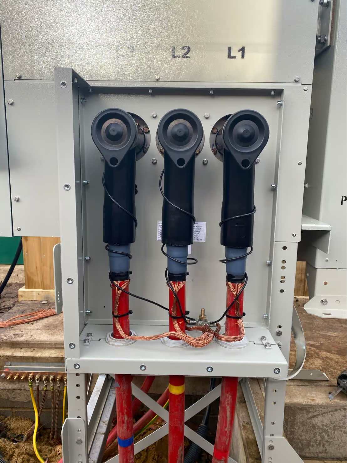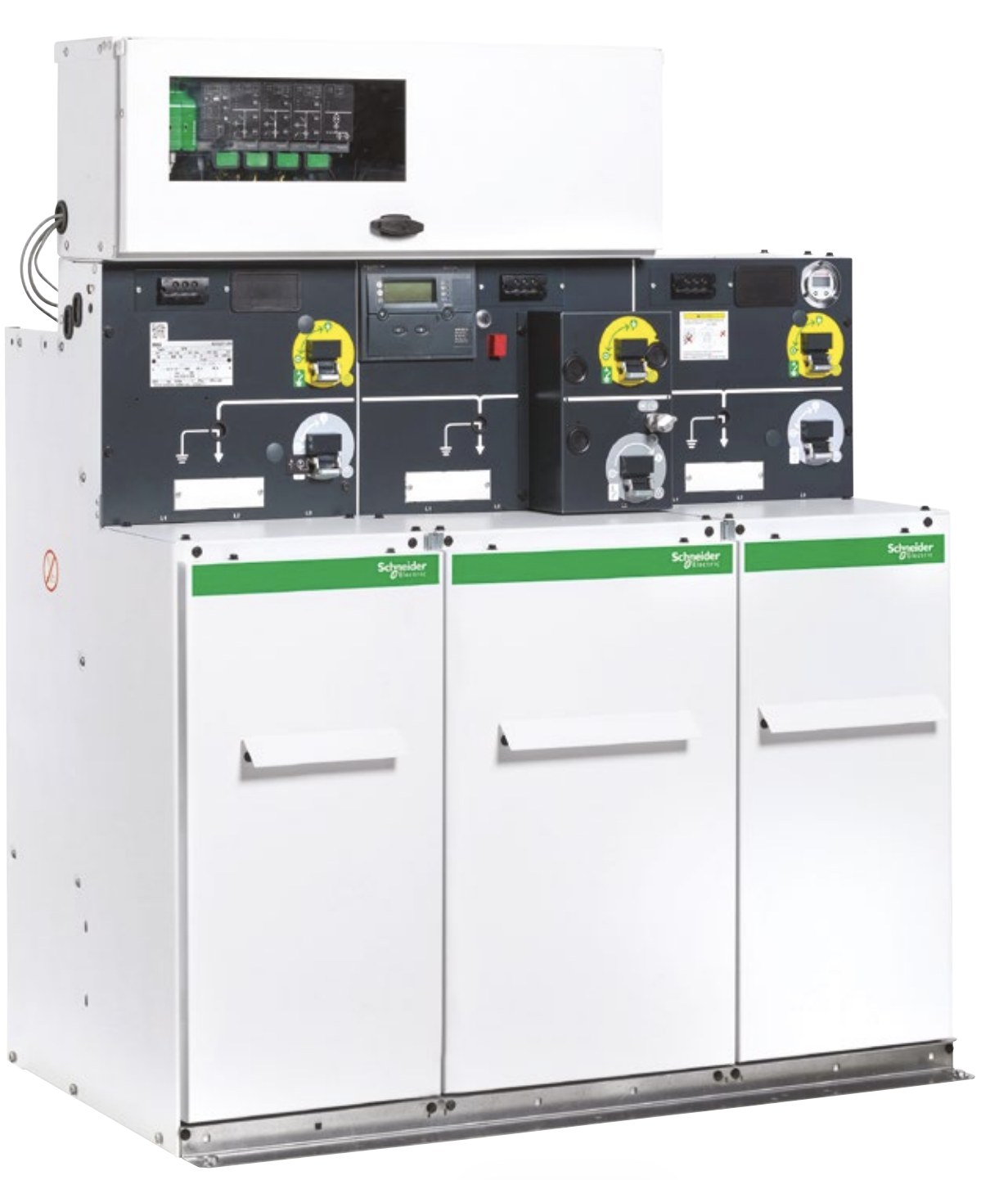

Gas-insulated medium-voltage switchgear — sealed-for-life SF6 panel for MV distribution

Gas-Insulated Switchgear (GIS) — Types, Selection & Specifications

Gas-insulated switchgear (GIS) is medium-voltage switchgear in which the live parts — busbars, switching devices and connections — are enclosed in a sealed metal tank filled with an insulating gas (traditionally SF6, increasingly SF6-free), rated for systems above 1 kV up to about 40.5 kV.

This pillar guide explains what gas insulation is and how it works, the GIS types and product families we supply, the shift from SF6 to SF6-free technology, how gas insulation compares with air, the key ratings and standards to specify, and how to select the right panel — for MV distribution projects across the Middle East and Gulf (including Egypt and Saudi Arabia), as well as North Africa, CIS and Sub-Saharan Africa.

What “gas-insulated” means (and where GIS fits)

In a gas-insulated panel the primary conductors sit inside a hermetically sealed enclosure filled with insulating gas, so the dielectric strength no longer depends on room air, humidity or altitude. Because the gas is far more effective than air, the same voltage and current ratings fit into a much smaller footprint, and the sealed tank makes the switchgear maintenance-free for its service life — the “sealed-for-life” or “sealed pressure system” concept defined in IEC 62271-200.

GIS belongs to the wider medium-voltage switchgear family. Where large primary substations often use air-insulated metal-clad panels, GIS dominates compact secondary distribution — ring main units, compact substations and space-limited or harsh-environment sites.
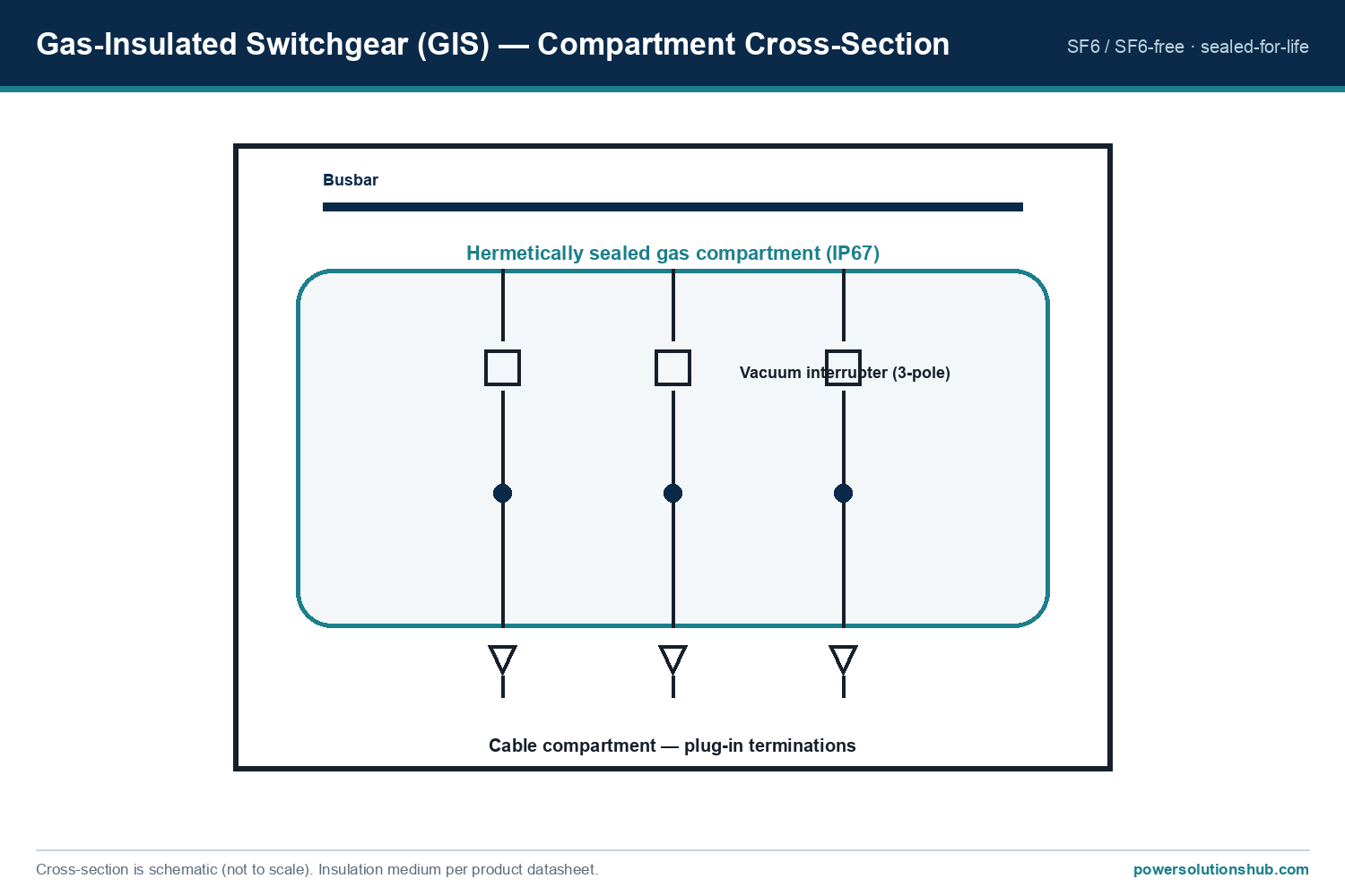
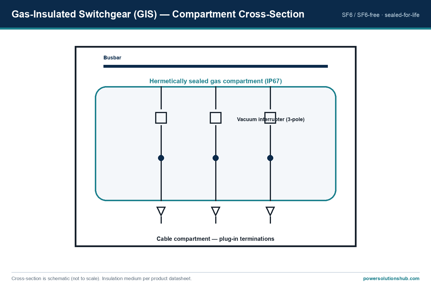
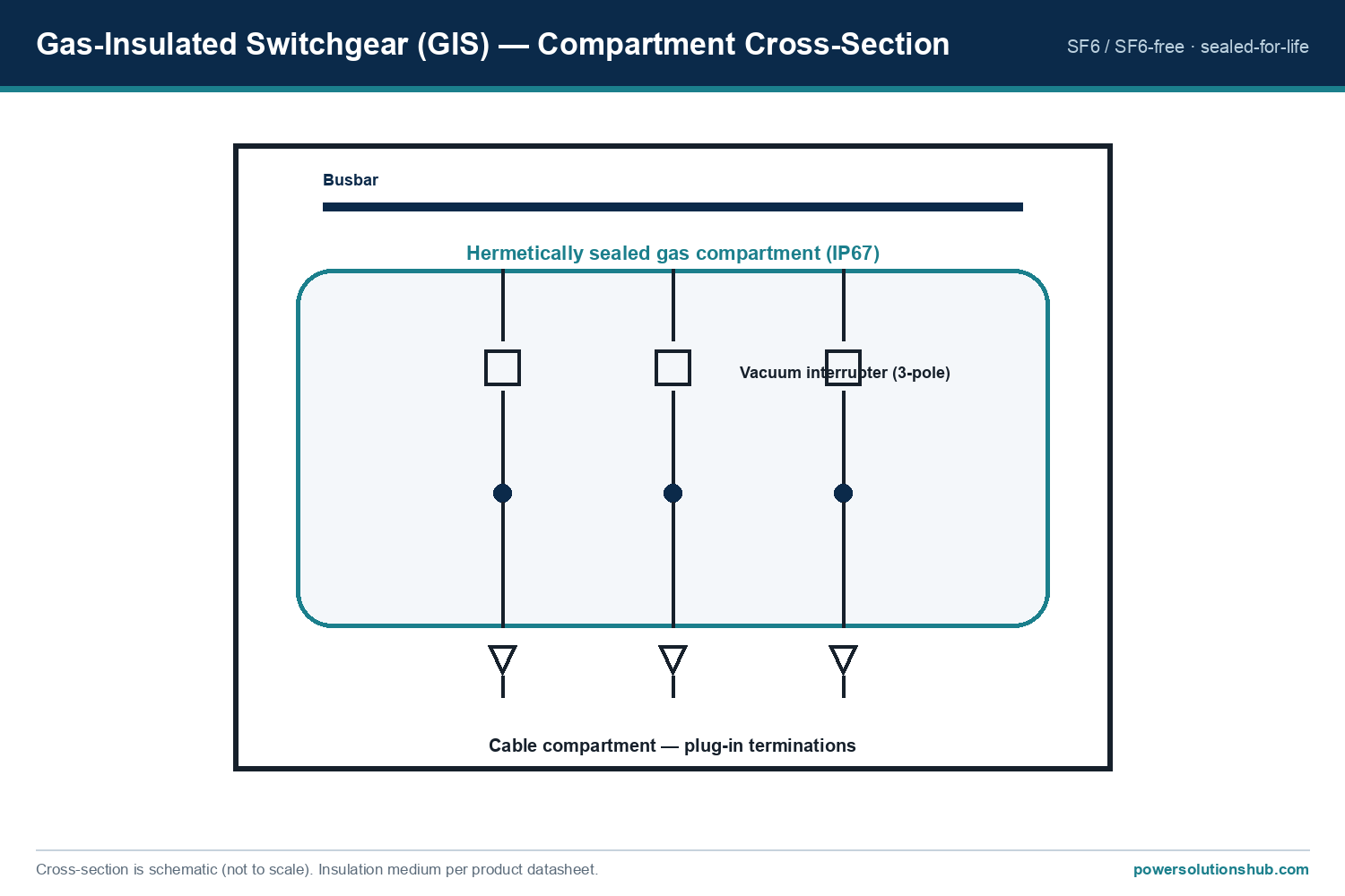
Gas-insulated switchgear compartment cross-section — sealed gas tank, vacuum interrupters and cable compartment
GIS compartment cross-section: the live parts and busbar sit in a hermetically sealed gas tank; cables connect via the lower compartment.

How gas insulation works

The role of the insulating medium is to withstand the electric field between live parts, and between live parts and earth, without breaking down. Insulating gas has a much higher dielectric strength than air at the same pressure, so the phase-to-phase and phase-to-earth clearances can be far smaller for the same rated voltage. That single property is why a 24 kV gas-insulated panel can be a fraction of the volume of an equivalent air-insulated one.

Two design ideas follow from this:

  • Sealed pressure system (“sealed-for-life”). The gas is enclosed in a welded steel tank that is filled and sealed at the factory and never opened in service. IEC 62271-200 recognises this as a sealed pressure system with an expected operating life during which no gas handling is required. Manufacturers describe the primary enclosure as hermetically sealed and safe-to-touch, independent of the external environment.
  • Vacuum switching inside the gas tank. Modern MV gas-insulated panels do the actual current interruption with a vacuum interrupter (vacuum circuit-breaker or vacuum-tight switch), while the gas provides the standing insulation. Siemens 8DJH, for example, uses a vacuum circuit-breaker with a three-position disconnector inside its sealed vessels.

Because the tank is sealed for life, the internal parts are protected from dust, humidity, condensation and pollution — the reason GIS keeps its dielectric performance in conditions that would derate or foul an air-insulated panel.

GIS types and product families

GIS is supplied in several formats depending on the role in the network:

  • Gas-insulated ring main units (RMUs): compact sealed units for secondary distribution — for example the Schneider RM6, ABB SafeRing / SafePlus and Siemens 8DJH. These combine ring load-break switches with transformer protection (fuse-switch or circuit-breaker) in one sealed tank. See the ring main unit pillar for the RMU function in detail.
  • Extensible / block-type secondary GIS: panels that can be extended on site as the network grows — SafeRing/SafePlus offer an extendable version, and 8DJH is a modular block system for secondary distribution up to 24 kV.
  • SF6-free gas-insulated switchgear: newer families that replace SF6 with dry/technical air or another low-GWP medium while keeping the sealed, compact design (covered in detail below).

GIS product families at a glance

The gas-insulated families we most often supply for MV secondary distribution:

Family Insulation Rated voltage Typical current Notes
Schneider RM6 SF6, sealed-for-life 12 / 17.5 / 24 kV 400 / 630 A Modular functional units (I/Q/D/B); Isc up to 25 kA
ABB SafeRing / SafePlus SF6, sealed-for-life 12 / 24 kV (also 36 kV) up to 630 A RMU + extensible; fuse-switch or vacuum CB feeder
ABB SafeRing / SafePlus Air Dry air (SF6-free), sealed up to 24 kV up to 630 A GWP = 0; vacuum CB with disconnector; IAC AFLR 20 kA 1 s
Siemens 8DJH SF6, sealed-for-life up to 24 kV up to 630 A Vacuum CB; panels tested to internal faults up to 21 kA

For the construction and insulation split across the whole switchgear family, see the medium voltage switchgear pillar, which separates insulation medium (gas vs air) from construction format (metal-clad, ring main unit).

SF6 vs SF6-free gas-insulated switchgear

For decades SF6 was the standard MV insulating gas because of its excellent dielectric and arc-quenching properties. Its drawback is environmental: SF6 is a potent greenhouse gas with a global warming potential (GWP) of roughly 23,000 times that of CO₂ — Siemens switchgear datasheets cite a GWP of 22,800, and the IPCC (Sixth Assessment Report) value is 24,300 — which has made it the target of tightening regulation such as the EU F-gas Regulation (EU 2024/573).

SF6-free gas-insulated switchgear keeps the sealed, compact concept but replaces SF6 with a low-GWP medium, most commonly dry / clean air combined with vacuum interruption:

  • Dry-air sealed RMUs — e.g. ABB SafeRing/SafePlus Air, a sealed ring main unit that uses dry air with a global warming potential of 0 and a vacuum circuit-breaker with disconnector, rated up to 24 kV with internal-arc accessibility AFLR 20 kA 1 s to IEC 62271-200.
  • Pure-air + vacuum modular switchgear — e.g. Schneider SM AirSeT, an SF6-free range that combines pure air for insulation and vacuum for arc interruption (Shunt Vacuum Interruption, SVI), with the load-break switch mounted in a sealed tank filled with air containing a vacuum bottle.
  • SF6-free air-insulated secondary switchgear — e.g. ABB UniSec Air, up to 24 kV, 1250 A and 25 kA, fully compliant with the EU F-gas regulation and using a dedicated vacuum interrupter (this is an air-insulated family; see the parent pillar for the insulation-vs-construction distinction).

The practical takeaway for a specifier: SF6-free MV switchgear now offers the same ratings and sealed-for-life convenience as SF6, with a clear regulatory and environmental advantage. Where a project or utility mandates SF6-free equipment, a like-for-like alternative is available across the RMU and secondary-distribution range.

GIS vs AIS — how to choose

The core selection question is insulation medium: gas-insulated (GIS) or air-insulated (AIS).
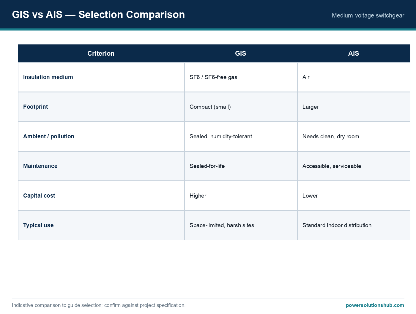
GIS vs AIS selection comparison — insulation, footprint, environment, maintenance and cost
Indicative GIS-vs-AIS comparison to guide selection; confirm against the project specification.
Criterion Gas-insulated (GIS) Air-insulated (AIS)
Insulation medium SF6 or SF6-free gas, sealed tank Air
Footprint Compact Larger
Ambient / pollution Sealed, humidity- and pollution-tolerant Needs a clean, dry, controlled room
Maintenance Sealed-for-life, minimal Accessible and serviceable
Capital cost Higher Lower
Typical use Space-limited, hot or harsh sites, secondary distribution Standard indoor distribution, large primary substations

Beyond the headline comparison, the decision is really about total cost of ownership and site conditions. A GIS panel costs more to buy, but its sealed enclosure removes the need for a large, clean, climate-controlled switch room and cuts internal maintenance to near zero over its life. An AIS panel is cheaper and easier to inspect and service, but it needs the space and the controlled environment to keep its air clearances clean and dry. On a compact urban plot, an offshore or desert site, or a project with limited maintenance access, the sealed GIS solution frequently wins on lifetime cost even though its purchase price is higher.

Selecting GIS for hot and harsh climates

For Gulf and North-African projects — high ambient temperature, dust, humidity and coastal salt — the sealed GIS enclosure is often decisive, because its dielectric performance does not degrade with room conditions. Three engineering points matter when specifying for these markets:

  1. Temperature derating. Rated normal current derates with ambient temperature. In installations where indoor temperatures routinely exceed 45 °C, apply the manufacturer’s derating before confirming the rated current — a 630 A busbar may be limited well below 630 A at 55–60 °C.
  2. Sealed enclosure vs pollution. Because the live parts are hermetically sealed, dust, humidity and salt do not reach them, so GIS avoids the flashover and tracking risks that pollution creates on exposed air-insulated parts.
  3. Compactness. Where floor area or substation footprint is constrained — kiosks, basements, packaged substations — the smaller GIS volume is a direct project benefit.

Key ratings to specify

When specifying a GIS panel, confirm these ratings against the manufacturer’s datasheet for your configuration:

Parameter Typical MV GIS range
Rated voltage Ur 12 / 17.5 / 24 kV (families up to 36–40.5 kV)
Rated normal current 400 A / 630 A (busbar); higher on primary GIS
Rated short-circuit / short-time current up to ~25 kA (secondary GIS); higher on primary
Internal-arc withstand tested to internal-arc fault levels (e.g. 8DJH up to 21 kA)
Insulation SF6 or SF6-free, hermetically sealed tank (sealed-for-life)
Standard IEC 62271-200 (AC metal-enclosed switchgear 1 kV–52 kV)

The ABB SafeRing/SafePlus and Siemens 8DJH families are type-tested to the IEC 62271 series — including IEC 62271-100 (circuit-breakers), -102 (disconnectors), -103 (switches) and -105 (switch-fuse combinations) — with the complete panel to IEC 62271-200.

Internal-arc safety

Even a sealed panel must be safe if an internal fault occurs. Internal Arc Classification (IAC) to IEC 62271-200 states the accessibility that is protected (type A for authorised personnel, sides F/L/R) and the tested arc current and duration — for example AFLR 20 kA for 1 s. In a fault, a pressure-relief path directs the hot gases away from the operator, and the earthed metal enclosure contains the event. A gas-insulated RMU such as SafeRing Air is classified AFLR 20 kA 1 s, and the Siemens 8DJH panels are tested for resistance to internal faults up to 21 kA.

Standards

The governing standard for MV GIS is IEC 62271-200 (AC metal-enclosed switchgear and controlgear for rated voltages above 1 kV and up to and including 52 kV). Gas-insulated panels are built as sealed pressure systems with a defined service life, and are classified by loss-of-service-continuity category (LSC), partition class (PM/PI) and internal-arc classification (IAC). The switching devices themselves follow the matching parts of the series — -100 (circuit-breakers), -102 (disconnectors), -103 (switches) and -105 (switch-fuse combinations) — and for a compact secondary substation the enclosure may also be type-tested to IEC 62271-202 (high-voltage/low-voltage prefabricated substations).

Applications

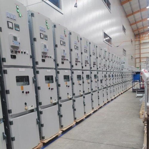
Gas-insulated switchgear is the workhorse of secondary distribution: compact substations and kiosks, utility ring networks, industrial and infrastructure distribution, renewable connection points and any space-limited or environmentally demanding installation. A gas-insulated ring main unit typically sits where an MV ring drops down to a distribution transformer, switching the incoming and outgoing cables and protecting the transformer — see the plug-in cable termination guide for how cables connect to a sealed GIS panel, and the ring main unit pillar for the secondary-distribution role in detail.

What is gas-insulated switchgear (GIS)?

GIS is medium-voltage switchgear whose live parts are enclosed in a sealed metal tank filled with insulating gas (SF6 or an SF6-free alternative), making it compact and maintenance-free for its service life to IEC 62271-200.

What is the difference between GIS and AIS?

GIS uses insulating gas in a sealed tank, so it is compact and tolerant of humidity and pollution; AIS uses air and needs a larger, clean, dry room. GIS has a higher capital cost but lower maintenance and a smaller footprint.

Is GIS always SF6-insulated?

No. Traditional GIS uses SF6, but SF6-free families now use dry/clean air with vacuum interruption (for example ABB SafeRing Air or Schneider SM AirSeT) while keeping the sealed, compact design, in response to F-gas regulations.

Why move away from SF6?

SF6 is a potent greenhouse gas with a GWP of roughly 23,000 times CO₂, and regulations such as the EU F-gas Regulation (EU 2024/573) are restricting its use; SF6-free alternatives now offer the same ratings with a GWP of 0.

What voltage does MV gas-insulated switchgear cover?

Typical MV GIS covers 12, 17.5 and 24 kV, with families extending to 36–40.5 kV; the governing standard IEC 62271-200 applies from above 1 kV up to 52 kV.

Is gas-insulated switchgear maintenance-free?

The sealed gas tank is a “sealed-for-life” (sealed pressure system) design to IEC 62271-200 and is maintenance-free internally for its service life; external operating mechanisms still follow the manufacturer’s service schedule.

How does GIS interrupt fault current?

Modern MV GIS uses a vacuum interrupter (vacuum circuit-breaker or vacuum-tight switch) for the actual current interruption, while the insulating gas provides the standing dielectric insulation inside the sealed tank.

Looking for Gas-Insulated Switchgear (GIS)?

Looking for high-quality gas-insulated MV switchgear and ring main units? We provide expert engineering support and reliable products for all your medium voltage needs.

For quotations and requests: info@electricistanbul.com

WhatsApp: +90 501 076 69 91
Plug-in cable termination on gas-insulated MV switchgear — cover

Plug-in Cable Termination on Gas-Insulated MV Switchgear (Separable Connectors)

A plug-in cable termination — more precisely a separable connector — is a screened, touch-proof MV cable accessory that pushes onto the bushing of gas-insulated switchgear, so a cable can be connected or disconnected without cutting into the insulation.

This guide explains how a plug-in cable termination works on gas-insulated MV switchgear, the interface types you will meet, the four assembly steps, and how to select the right connector — with common mistakes to avoid.

Why use a plug-in cable termination on gas-insulated switchgear?

Gas-insulated switchgear (GIS) and ring main units are sealed for life, so their cable connection has to be made from outside the tank, onto standardised bushings. A plug-in cable termination provides exactly that: a screened (fully insulated, earthed outer layer) plug that mates with the bushing, is touch-proof, and can be removed for testing without disturbing the cable. This is what makes the compact, maintenance-free gas-insulated switchgear design practical in the field.

Plug-in cable termination in the lower cable compartment of gas-insulated switchgear
Separable connectors land in the lower cable compartment of gas-insulated switchgear.

Interface types and current ratings

Separable connectors are standardised by a bushing interface defined in CENELEC EN 50180 / EN 50181, and each interface has a current class. The Nexans Euromold range covers cables from 12 up to 42 kV. The common interfaces are:

Interface Rated current Voltage Typical Euromold products Type
Interface A 250 A up to 24 kV 158LR elbow, 152SR straight, K200T tee screened, separable
Interface C (400-series) 630 A up to 24 kV K400-series elbow / tee connectors screened, separable
Interface C (480-series) 1250 A up to 24 kV tee / cross connectors screened, separable

Interface A (250 A) is the workhorse for distribution transformers and small feeders; the 630 A and 1250 A interfaces are used where the feeder current or ring-through current is higher.

The bushing part accepts interface diameters between 40 and 60 mm, and the system is separable, allowing easy removal for testing. A typical screened elbow connector (e.g. 158LR) is built from a conductive EPDM insert and jacket, a conductor connector, a capacitive voltage test point, and — in the earthed (-G) version — an earthing lead.

Screened vs unscreened — why touch-proof matters

The single most important distinction is whether a connector is screened. A screened separable connector carries a semi-conductive outer layer that is bonded to earth, so the exposed surface stays at earth potential even when the cable is live. That makes the assembly touch-proof and lets it be operated safely inside a compact, sealed switchgear cabinet where clearances are small. Unscreened accessories have no earthed outer layer and are restricted to applications where touch-proofing is not required. On gas-insulated switchgear — where the whole point is a sealed, space-saving enclosure — screened, touch-proof connectors are effectively mandatory. The screened design is also what allows tee and cross connectors to be stacked on a single bushing to build ring and tap-off arrangements.

Function types — elbow, tee and cross

The elbow (angled) connector terminates a single cable onto a bushing; the tee connector provides a through-connection so a bushing can carry the ring plus a tap-off; and the cross connector extends this to multiple tap-offs. Unused positions are closed with dead-end plugs, and surge arresters (e.g. the 156SA) or stand-off / earthing plugs can be added onto the same interface. This building-block approach mirrors the switchgear itself and is why the accessory interface is standardised so strictly.

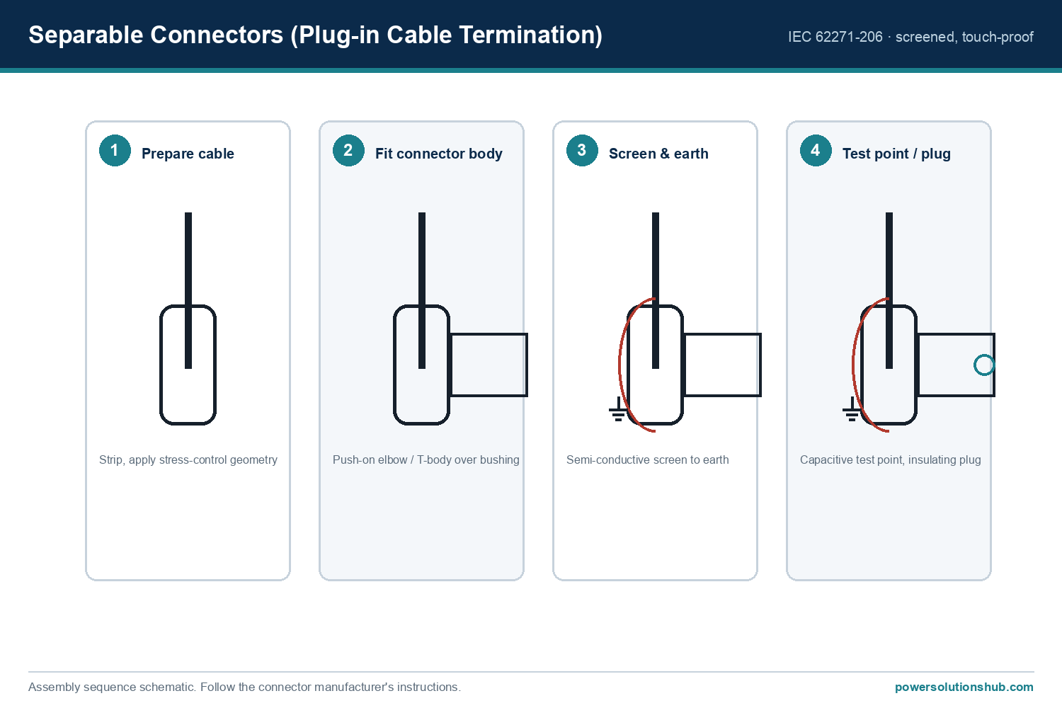
Fitting a plug-in cable termination: the four steps

Plug-in cable termination assembly sequence: prepare cable, fit body, screen and earth, test point and plug
The screened plug-in cable termination assembly sequence.
  1. Prepare the cable. Strip the cable to the connector’s dimensions and apply the stress-control geometry that controls the electric field at the screen cut-back.
  2. Fit the connector body. Push the elbow or T-body over the equipment bushing until seated.
  3. Screen and earth. Connect the semi-conductive outer screen to earth, making the assembly touch-proof.
  4. Test point / plug. Fit the capacitive voltage test point and any insulating plug; unused positions of a tee are closed with a dead-end plug.

Selecting a plug-in cable termination

When you select a plug-in cable termination, five factors decide the right part:

  • Interface & current: match Interface A (250 A), 630 A or 1250 A to the feeder current.
  • Voltage class: e.g. 12/20 (24) kV — select the connector’s rated voltage above the network’s Ur.
  • Cable type: confirm the connector suits the cable’s conductor size and screen type (e.g. copper-tape or wire screen).
  • Function: elbow (single cable), tee (through-connection / ring), or cross (multiple tap-offs).
  • Standards: the products meet CENELEC HD 629.1, EN 50180/50181, IEC 60502-4 and IEC 60137.
Nexans Euromold separable connector fitted to a medium-voltage cable
Nexans Euromold separable connector on an MV cable.

Common mistakes

  • Wrong interface pairing — the connector interface must match the switchgear bushing interface (A/C); they are not interchangeable.
  • Ignoring stress control — an incorrectly applied stress-control cone leads to partial discharge and early failure.
  • Screen not earthed — leaves the assembly no longer touch-proof.
  • Skipping the test point — the capacitive test point is needed to verify dead/live status safely before work.

Testing and commissioning

Before energising, the capacitive voltage test point on each connector is used to confirm the circuit is dead, and, after energising, to verify phase presence — without exposing any live metal. On commissioning, cable systems are typically subjected to an insulation and partial-discharge check; because the connector is separable, it can be taken off the bushing for these tests and refitted, which is a practical advantage over fixed heat-shrink terminations. Keeping the interface clean and correctly lubricated at assembly is what ensures a reliable, partial-discharge-free joint over the cable’s life.

A correctly specified plug-in termination is part of a coordinated MV system — the same fault levels that size the short-circuit rating also apply to the connector’s short-circuit withstand.

What is a plug-in cable termination?

A plug-in cable termination is a separable connector: a screened, touch-proof MV cable accessory that pushes onto a switchgear bushing so the cable can be connected or removed without cutting the insulation.

What is the difference between a screened and unscreened separable connector?

A screened connector has an earthed semi-conductive outer layer, making it touch-proof; unscreened types do not and are used only where touch-proofing is not required.

Which interface should I choose?

Match the switchgear bushing: Interface A (250 A) for most distribution feeders, or 630 A / 1250 A interfaces for higher currents.

Can separable connectors be disconnected for testing?

Yes — that is their main advantage. They are separable and include a capacitive voltage test point for safe verification.

What voltage levels do they cover?

The Euromold range covers cables from 12 up to 42 kV.

Looking for Plug-in Cable Terminations (Separable Connectors)?

Looking for high-quality separable connectors and MV cable terminations? We provide expert engineering support and reliable products for all your medium voltage needs.

For quotations and requests: info@electricistanbul.com

WhatsApp: +90 501 076 69 91
Schneider RM6 gas-insulated ring main unit — cover

Schneider RM6 Gas-Insulated Ring Main Unit — Selection & Specification Guide

The Schneider RM6 is a compact, SF6 gas-insulated ring main unit (RMU) for medium-voltage secondary distribution, rated up to 24 kV and built around modular functional units that combine switching, transformer protection and earthing in a sealed enclosure. It belongs to the ring main unit (RMU) family — see the RMU pillar for selection across brands.

This guide covers the RM6’s configurations (functional units), technical ratings, selection criteria and typical applications, so you can specify the right unit for a distribution substation across the Middle East and Gulf — including Egypt and Saudi Arabia — North Africa and CIS markets.

What the RM6 is (and where it fits)

A ring main unit sits at the secondary distribution level: it connects a substation into the MV “ring”, switches the incoming/outgoing cables, and protects the MV/LV distribution transformer. The RM6 does this in a sealed, gas-insulated tank — the live parts sit in SF6, so the unit is compact and largely maintenance-free for its service life.

It links directly to the wider medium-voltage switchgear family: where primary switchgear feeds large loads, the RM6 is the workhorse of compact secondary substations and kiosks.

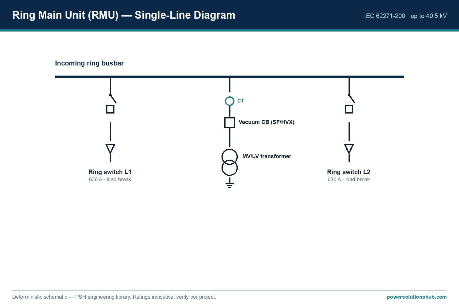
RM6 ring main unit single-line diagram — ring switches and protected transformer feeder
RMU single-line: two ring load-break switches plus a protected transformer feeder.

Configurations — RM6 functional units

The RM6 is assembled from standard functional units (modules), so you build the exact single-line you need. The core functions from the catalogue are:

  • I — line switch (incomer/feeder): a network point with a switch-disconnector, rated 400 A or 630 A.
  • Ic — bus coupler by switch-disconnector.
  • Q — fuse-switch combination: transformer protection by a switch + MV fuses, for transformers up to 2 000 kVA (limited to 200 A).
  • D / B — circuit-breaker function: transformer or feeder protection by a 630 A circuit breaker with a protection relay, for transformers up to 8 000 kVA.

Units are ordered by extensibility: NE (non-extensible), RE (right-extensible), LE (left-extensible) and DE (double-extensible), so a substation can grow on site. Transformer feeders are protected either by the fuse-switch (Q) for smaller ratings or by a circuit breaker with a self-powered VIP-series protection relay for larger ratings.

Technical specifications

All values below are taken from the Schneider RM6 catalogue; confirm the exact figures against the ordering configuration for your project.

Parameter Value
Rated voltage Ur 12 / 17.5 / 24 kV
Rated frequency 50 or 60 Hz
Rated normal (busbar) current 400 A / 630 A
Short-circuit breaking capacity Isc up to 25 kA
Short-time withstand duration tk 1 s or 3 s
Peak making capacity Ima (switch & earthing) up to 62.5 kA peak
Internal arc classification AFLR 20 kA, 1 s (IEC 62271-200)
Insulation SF6, sealed-for-life tank
Switchgear classification PM (IEC 62271-200)
Switch-disconnector class M1 / E3, 100 CO cycles (IEC 62271-103)

The RM6 complies with IEC 62271-200 (AC metal-enclosed switchgear for rated voltages above 1 kV up to 52 kV) with an internal-arc classification of AFLR 20 kA for 1 s, and its switch-disconnectors follow IEC 62271-103 at class M1/E3 (100 close-open cycles).

Busbar current vs. ambient temperature

Rated current derates with ambient temperature — a key point for hot-climate projects. For the 630 A busbar:

Ambient temperature 40 °C 45 °C 50 °C 55 °C 60 °C
630 A busbar — usable Ir 630 A 575 A 515 A 460 A 425 A

In Gulf and North-African installations where indoor temperatures routinely exceed 45 °C, this derating should be applied before confirming the rated current.

Gas-insulated switchgear compartment cross-section showing the sealed SF6 tank and cable compartment
The RM6's live parts sit in a sealed gas compartment; cables connect via the lower compartment.

Selection criteria

  1. Transformer rating → protection type. Up to 2 000 kVA, a Q (fuse-switch) unit is typically sufficient; above that, up to 8 000 kVA, use a circuit-breaker (D/B) unit with a protection relay.
  2. Rated current. Choose 400 A or 630 A busbars, then apply the ambient-temperature derating above.
  3. Short-circuit level. Confirm the network’s prospective fault current against the RM6’s Isc (up to 25 kA) and making capacity.
  4. Extensibility. Pick NE/RE/LE/DE to match whether the substation will be extended later.
  5. Voltage class. 12, 17.5 or 24 kV per the network’s rated voltage.
Schneider RM6 ring main unit — front view of the functional units
Schneider RM6 ring main unit, front view.

How the RM6 is built and extended

Because the RM6 is modular, a substation is specified as a string of functional units — for example a two-incomer, one-transformer layout is an I-I-Q (two ring switches plus a fuse-switch transformer feeder), while a protected feeder substation might be I-I-D (two ring switches plus a circuit-breaker feeder). The extensibility code chosen at order time (NE, RE, LE, DE) decides whether more modules can be bolted on later without replacing the unit: a DE (double-extensible) unit can grow on either side as the network develops. This “build-what-you-need, extend-later” approach is a large part of why RMUs dominate secondary distribution.

Interlocking is built in: the earthing switch has a short-circuit making capacity, and mechanical interlocks make it impossible to earth a circuit that is still energised — a safety feature required by IEC 62271-200 and reflected in the unit’s simple front mimic diagram.

Applications

The RM6 is used in compact secondary substations, kiosks and building distribution — utilities, industry, infrastructure and renewable connection points — anywhere a sealed, space-saving RMU is needed to ring-connect and protect an MV/LV transformer. In practice it sits at the point where an MV distribution ring drops down to a 1 000–2 000 kVA (fuse-switch) or larger (circuit-breaker) transformer, feeding a low-voltage board. Its low centre of gravity and sealed tank also make it suitable for demanding environments, including IACS-compliant marine installations.

Its protection is coordinated with downstream devices; for the protection side, see medium-voltage protection relays. Within the gas-insulated RMU family it competes directly with ABB SafeRing/SafePlus and Siemens 8DJH; the RM6’s differentiator is its wide, freely combinable functional-unit range and on-site extensibility.

What voltage and current is the Schneider RM6 rated for?

The RM6 is rated for 12, 17.5 and 24 kV, with busbar currents of 400 A or 630 A and a short-circuit breaking capacity up to 25 kA.

Is the RM6 SF6-insulated?

Yes — the RM6 is a gas-insulated ring main unit; its live parts are enclosed in a sealed SF6 tank, making it compact and maintenance-free for its service life.

What is the RM6’s internal arc classification?

The RM6 is classified IAC AFLR 20 kA for 1 s to IEC 62271-200.

What do the RM6 functional units (I, Q, D) mean?

I is a line switch-disconnector, Q is a fuse-switch for transformer protection (up to 2 000 kVA), and D/B is a circuit-breaker function with a protection relay (transformers up to 8 000 kVA).

How do I protect the transformer with an RM6?

Use a Q (fuse-switch) unit for transformers up to 2 000 kVA, or a circuit-breaker unit with a protection relay for ratings up to 8 000 kVA.

Looking for Schneider RM6 Ring Main Units?

Looking for high-quality Schneider RM6 gas-insulated ring main units? We provide expert engineering support and reliable products for all your medium voltage needs.

For quotations and requests: info@electricistanbul.com

WhatsApp: +90 501 076 69 91
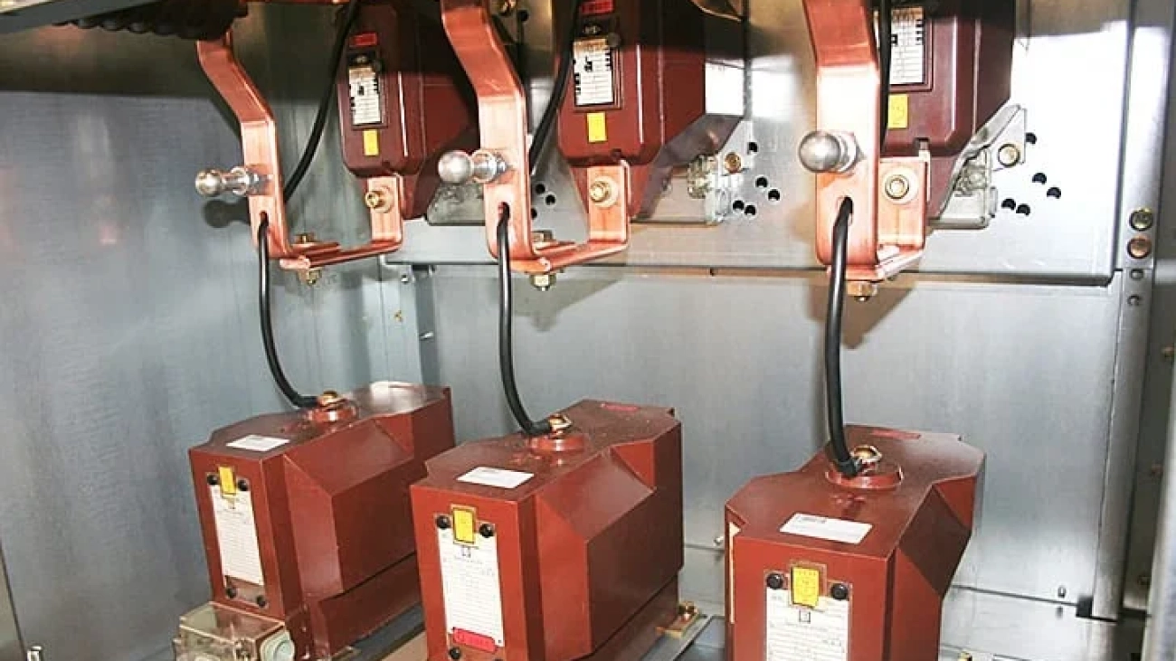
mv current transformer

What is Voltage Transformer?

What is a Voltage Transformer? Role of MV Voltage Transformers in Medium Voltage Systems

A voltage transformer is a fundamental instrument transformer used in electrical power systems to step down high voltages to safe, standardized levels suitable for measurement and protection devices. In medium voltage networks, particularly those operating up to 36 kV, the voltage transformer plays a vital role by providing accurate voltage signals to energy meters, protection relays, and monitoring equipment while ensuring complete electrical isolation from the high-voltage primary circuit.

Direct measurement of medium or high voltages is both dangerous and technically impractical. The voltage transformer solves this by reducing the primary voltage (typically in the range of 3.6 kV to 36 kV) to a low secondary voltage, most commonly 100 V or 110 V. This allows operators and sensitive electronic devices to work safely while maintaining high accuracy in voltage measurement and fault detection.

What is a voltage transformer in practical terms? It functions as both a voltage divider and a safety barrier. Without it, protection relays could not reliably detect overvoltages or undervoltages, and energy metering would be impossible in medium voltage installations.

Purpose and Importance of Voltage Transformers in MV Systems

In medium voltage switchgear and substations, the voltage transformer serves two primary purposes: metering and protection. For metering applications, it supplies precise voltage signals to energy meters and power quality analyzers, enabling accurate billing and monitoring. For protection purposes, it provides input to relays that detect abnormal voltage conditions, initiate tripping, or trigger alarms during overvoltage events.

A well-designed voltage transformer ensures that protection systems respond quickly and correctly while maintaining measurement accuracy under both normal and fault conditions. Incorrect selection or installation can lead to measurement errors, delayed protection response, and reduced equipment lifespan.

Technical Specifications of Medium Voltage Voltage Transformers

Medium voltage voltage transformers are manufactured to strict international standards such as IEC 61869-3. Typical technical parameters include:

  • Primary voltage range: 3.6 kV to 36 kV (covering common medium voltage levels including 33kV voltage transformer applications)
  • Secondary voltage: 100 V or 110 V (standardized values)
  • Rated frequency: 50 Hz or 60 Hz
  • Insulation type: Epoxy resin cast (most common for indoor use), oil-immersed, or gas-insulated (for outdoor or special environments)
  • Mounting options: Indoor or outdoor, with horizontal or vertical installation

For indoor applications in compact medium voltage modular cells, epoxy resin cast voltage transformers are preferred due to their excellent insulation properties and small footprint. In outdoor environments, oil-immersed designs offer superior durability against weather conditions.

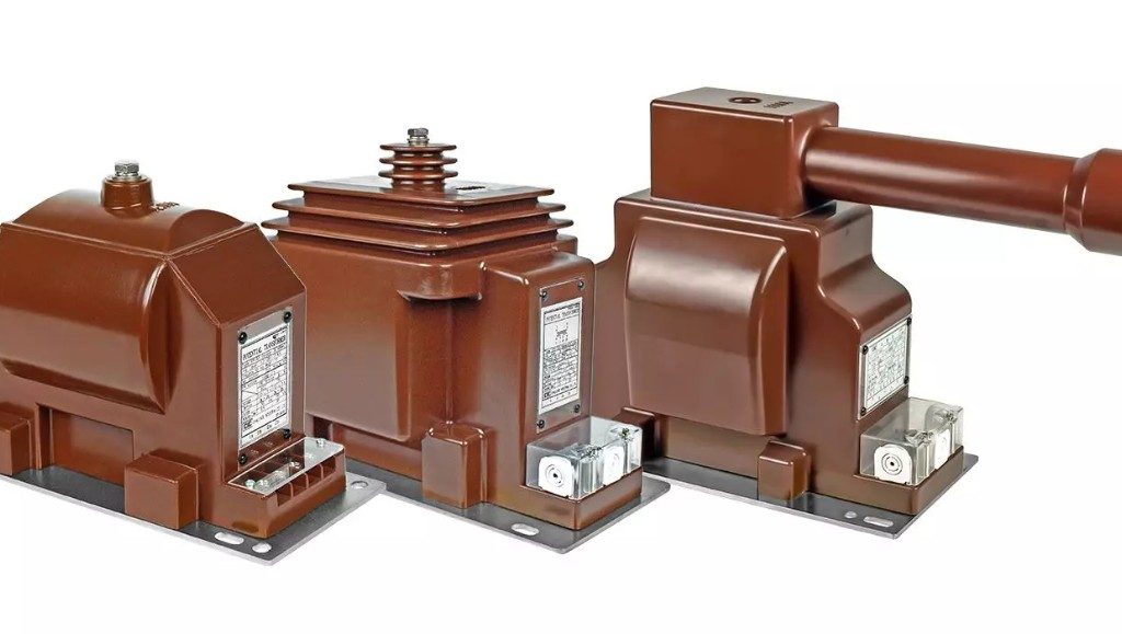
voltage transformer
A voltage transformer is a fundamental instrument transformer used in electrical power systems to step down high voltages to safe, standardized levels suitable for measurement and protection devices.

Difference Between Current Transformer and Voltage Transformer

Although both instrument transformers are essential in medium voltage systems, there is a fundamental difference between current transformer and voltage transformer in terms of function and connection:

  • A voltage transformer is connected in parallel (shunt) with the circuit. It steps down voltage and provides a voltage signal proportional to the primary voltage.
  • A current transformer is connected in series with the circuit. It steps down current and provides a current signal (usually 1 A or 5 A) proportional to the primary current.

In practice, medium voltage metering compartments often use both devices together. The voltage transformer supplies voltage information while the current transformer supplies current information. Together, they allow complete monitoring of power parameters such as active power, reactive power, and energy consumption.

Selection Criteria for Voltage Transformers

Choosing the correct voltage transformer requires careful evaluation of several parameters:

  • System voltage level (for example, selecting the right 33kV voltage transformer for 33 kV networks)
  • Application type: metering or protection
  • Accuracy class (common classes include 0.5 for metering and 3P or 6P for protection)
  • Burden (VA rating) required by connected devices
  • Environmental conditions (indoor/outdoor, temperature, pollution level)
  • Mounting and insulation type

Proper selection according to these criteria ensures measurement accuracy, reliable protection performance, and long service life. Voltage transformers used in TEDAŞ projects in Turkey, for example, must also comply with local technical specifications in addition to international standards.

Applications of Medium Voltage Voltage Transformers

Voltage transformers are widely used in:

  • Medium voltage modular switchgear (especially in the metering and protection compartments)
  • Transformer substations
  • Power generation plants
  • Industrial distribution panels
  • Capacitor banks and power quality monitoring systems
  • Revenue metering points before energy meters

In all these applications, the voltage transformer ensures that critical voltage information reaches protection and control systems safely and accurately.

Selecting the Right Voltage Transformer for Medium Voltage Applications

A properly selected and installed voltage transformer is indispensable for safe, accurate, and reliable operation of medium voltage power systems. From providing precise metering signals to enabling fast and correct protection response, these devices form the backbone of voltage measurement and control in networks up to 36 kV, including common 33kV voltage transformer installations.

Looking for Voltage Transformer for your project?

Looking for high-quality voltage transformer solutions, including 33kV voltage transformer options, or need support understanding the difference between current transformer and voltage transformer? We provide expert engineering assistance and reliable products for all your medium voltage measurement and protection requirements.

For quotations and requests: info@electricistanbul.com

Whatsapp: +90 501 076 69 91
mv current transformer

What is MV Current Transformer?

What is a Current Transformer? MV Current Transformer (Medium Voltage Current Transformer)

A current transformer (CT), also known as an MV current transformer in medium voltage systems, is a critical instrument transformer used to accurately and safely measure high currents in power distribution networks.

In high-voltage and high-current circuits, measuring current directly is both dangerous and impractical. A current transformer steps down the high primary current to a safe, standardized secondary current (usually 1A or 5A) that can be used by measuring devices, protection relays, and energy meters.

MV current transformers provide excellent electrical isolation between the high-voltage primary side and the low-voltage secondary side, ensuring operator safety and protecting sensitive equipment.

These transformers are widely used in medium voltage switchgear (up to 36 kV), transformer substations, distribution panels, and industrial facilities for both metering and protection purposes.

Current Transformer Working Principle

A current transformer operates on the principle of electromagnetic induction, similar to a power transformer.

The primary winding (usually consisting of one or very few turns of thick conductor) carries the high load current. This current creates a magnetic flux in the core, which induces a proportional current in the secondary winding (made of many turns of finer wire).

The current transformer ratio (CT ratio), such as 600/5, defines the relationship between primary and secondary current. This transformation allows accurate monitoring while keeping the measurement circuit safe.

Current Transformer Classification and Selection Criteria

Current transformers are classified according to their accuracy class, burden (VA), and application (metering or protection).

Key selection parameters for MV current transformers include:

  • Accuracy Class
  • Current Transformer Class (e.g., 0.5, 1, 5P, 10P)
  • Rated Burden (VA)
  • Thermal and Dynamic Short-Circuit Withstand
  • Current Transformer Accuracy

Metering current transformers are designed to saturate quickly during overcurrent conditions to protect instruments. Protection current transformers (typically 5P or 10P) maintain accuracy during fault conditions to ensure reliable relay operation.

The CT ratio must be chosen carefully according to the maximum load and short-circuit currents in the system.

Current Transformer Classes and Ratings

Common accuracy classes for metering current transformers are: 0.1 – 0.2 – 0.5 – 1 – 3

For protection purposes, 5P and 10P classes are most frequently used.

Important technical values:

  • Thermal withstand current (Ith): Minimum 100 × rated current
  • Dynamic withstand current: 2.5 × thermal withstand current

Safety Note: Never leave the secondary circuit of a current transformer open while the primary is energized. High voltage can be induced, creating serious risk to personnel and equipment. The secondary must always be short-circuited or connected to a load.

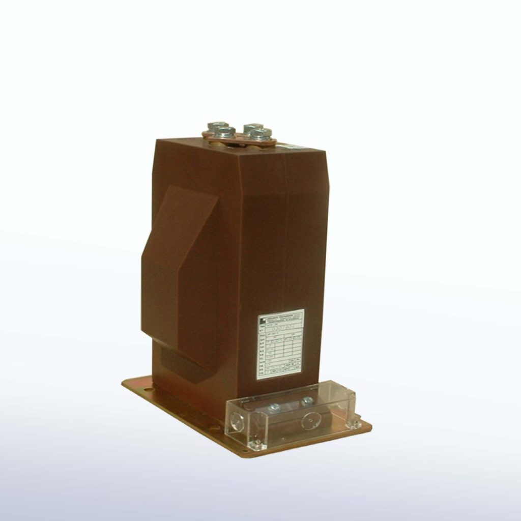
mv current transformer 2
A current transformer (CT), also known as an MV current transformer in medium voltage systems, is a critical instrument transformer used to accurately and safely measure high currents in power distribution networks.

Types of Current Transformer

There are several types of current transformer used in medium voltage systems:

  • Toroidal Current Transformer: Ring-type design, compact and widely used in MV switchgear. Also known as flexible current transformer in some applications.
  • Wound Type / Post Type (Mesnet Type): Epoxy resin cast, excellent insulation, suitable for both metering and protection.
  • LPCT (Low Power Current Transformer): Modern digital type that outputs voltage signal (mV) instead of traditional 1A/5A current.

ABB current transformer, Alce current transformer, and other reputable manufacturers offer high-quality solutions in all these categories.

Current Transformer Diagram and Applications

A typical current transformer diagram shows the primary conductor passing through the core and the secondary winding connected to meters or relays.

MV current transformers are essential in:

  • Medium voltage modular switchgear
  • Transformer substations
  • Industrial power distribution systems
  • Renewable energy projects
  • Protection and control panels

They play a vital role in accurate energy measurement, fault detection, and system protection.

Looking for MV Current Transformer?

Looking for high-quality MV current transformer, toroidal current transformer, ABB current transformer, or other types of current transformer solutions? We provide expert engineering support and reliable products for all your medium voltage needs.

For quotations and requests: info@electricistanbul.com

Whatsapp: +90 501 076 69 91
short circuit 3

Impact of Generators on Short Circuit Current in Power Systems

Impact of Generators on Short Circuit Current in Power Systems

In power system analysis, calculating short circuit current at any point in the network requires careful consideration of all contributing sources. Among these, synchronous and asynchronous generators play a particularly important role. Because of their internal construction, generators significantly influence the magnitude and behavior of short circuit current through armature reaction, field flux dynamics, and leakage reactances in both the stator and rotor.

When a short circuit occurs, a generator does not behave like a simple voltage source with fixed impedance. Instead, its effective reactance changes over time due to the physical response of the magnetic field. This time-dependent behavior is characterized by three distinct reactance values: subtransient reactance, transient reactance, and steady-state reactance. These parameters determine how the generator short circuit current evolves from the instant the fault occurs until it reaches a stable value.

Synchronous Generator Behavior During Short Circuits

A synchronous generator’s response to a short circuit is governed by the interaction between the stator current and the rotor field. Immediately after the fault, the armature reaction causes a rapid change in the magnetic flux. This leads to very high initial current values that decay in stages.

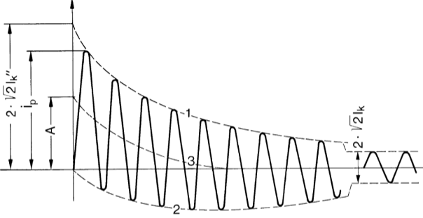
The first stage is the subtransient period, lasting only a few cycles. During this time, the effective reactance is at its lowest (subtransient reactance, typically denoted as X”d), resulting in the highest short circuit current. Following this, the transient period begins, where the reactance increases to the transient value (Xd’). Finally, the current settles into the steady-state value determined by the synchronous reactance (Xd).

This staged decay is critical because the highest mechanical and thermal stresses on equipment occur during the initial cycles. Protection engineers must account for these peak values when selecting circuit breakers and designing protection schemes.

Generator Close-in Short Circuit Analysis

When a short circuit occurs close to the generator terminals, the generator’s internal impedances dominate the fault current calculation. In this scenario, the subtransient period is relatively short. The high initial current caused by low subtransient reactance decays rapidly because the armature reaction quickly weakens the main field flux.

As the field weakens, the generator’s internal voltage drops, effectively increasing its impedance. Consequently, both the peak (asymmetrical) short circuit current and the symmetrical rms value decrease faster than in systems without local generation. This rapid decay means that while the initial current is very high, it stabilizes relatively quickly. Protection devices located near the generator must therefore be rated for these elevated initial values, even if the steady-state current is lower.

generator short circuit
Generator Close-in Short Circuit

Generator Remote Short Circuit Analysis

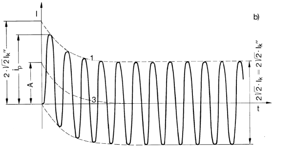
In contrast, when a short circuit occurs far from the generator, the impedance of the network between the generator and the fault location becomes much larger than the generator’s own impedance. In this case, the generator’s contribution to the total short circuit current is relatively small.

Because the network impedance limits the fault current, the initial peak and the steady-state values are much closer to each other. The subtransient and transient effects of the generator are masked by the dominant network impedance. As a result, the short circuit current does not show the dramatic initial spike and rapid decay seen in close-in faults. Instead, it remains relatively stable from the beginning of the fault.

This difference has important practical implications. In networks with distributed generation, engineers must perform detailed studies to determine whether a fault is electrically “close” or “remote” to each generator. The location directly affects the required breaking capacity of circuit breakers and the coordination of protective relays.

generator short circuit 2
Generator Remote Short Circuit

Importance for Protection System Design

Accurate modeling of generator short circuit behavior is essential for proper protection coordination and equipment sizing. Circuit breakers must be capable of interrupting the highest possible asymmetrical current that can occur during the subtransient period. Similarly, protection relays must be set correctly to detect faults quickly while maintaining selectivity.

Ignoring the time-varying reactances of generators can lead to under-rated equipment or incorrect relay settings, both of which compromise system reliability and safety. Modern short circuit analysis software allows engineers to model subtransient, transient, and steady-state conditions separately, providing a realistic picture of fault current evolution.

Impact of Generators on Short Circuit Current Calculations

Understanding how synchronous generators affect short circuit current through their time-dependent reactances is fundamental for reliable power system design. Whether the fault occurs near or far from the generator, proper consideration of subtransient, transient, and steady-state periods ensures that protection systems are correctly dimensioned and that equipment can withstand the mechanical and thermal stresses of faults.

Looking for Generator Short Circuit Analysis for your project?

Looking for detailed generator short circuit studies, protection coordination, or correctly rated switching equipment for systems with synchronous or asynchronous generators? We provide expert engineering support and reliable solutions tailored to your power system requirements.

For quotations and requests: info@electricistanbul.com

Whatsapp: +90 501 076 69 91
short circuit 3

What is Short Circuit in Power Systems?

What is Short Circuit? Understanding Short Circuit Meaning and Definition in Power Systems

A short circuit is one of the most critical faults in electrical power systems. According to international standards such as IEC and IEEE Std. 100-1992, a short circuit occurs when two or more points in an electrical circuit that normally operate at different voltages come into unintended contact through a path of very low resistance or impedance. This creates an abnormal, high-magnitude current flow known as short circuit current.

In simple terms, the short circuit meaning refers to a situation where the normal load path is bypassed, allowing current to take the path of least resistance. The magnitude of this current is determined by the total impedance between the power source and the fault location. When impedance drops dramatically, the current can reach several times its normal value within milliseconds, generating intense heat and powerful electromagnetic forces.

What is a short circuit in practical terms? It typically happens between phases (line-to-line), between a phase and neutral, or between a phase and ground (earth). In medium and high-voltage networks, these faults often begin as single-phase events and can rapidly evolve into more severe multi-phase faults through arcing.

short circuit 2
A short circuit is one of the most critical faults in electrical power systems.

Common Causes of Short Circuits

Short circuits can result from both internal and external factors. Internal causes include insulation degradation due to aging, manufacturing defects, or excessive thermal stress from overloading. Overvoltages can also puncture insulation, creating conductive paths.

External causes are more varied and often unpredictable. These include physical damage to cables or overhead lines, lightning strikes on transmission systems, broken insulators, contamination combined with moisture, bird contact on live parts, or even animals entering transformer substations. Human errors during maintenance, such as leaving earthing switches closed when re-energizing equipment, are another frequent trigger.

Types of Short Circuit Faults

Power system engineers classify short circuit faults into four main categories:

  • Three-phase short circuit (symmetric fault)
  • Phase-to-phase short circuit
  • Phase-to-ground (single line to ground) short circuit
  • Phase-to-phase-to-ground (double line to ground) short circuit

The three-phase short circuit is symmetrical and produces the highest current magnitude, though it occurs less frequently. In contrast, phase-to-ground faults account for more than 50% of all short circuit events in distribution networks and are asymmetrical in nature. Accurate short circuit calculations for each type are essential for proper equipment sizing and protection coordination.

Effects and Dangers of Short Circuits

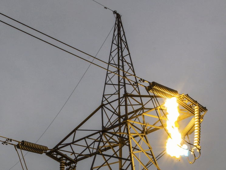
The consequences of a short circuit can be severe. The sudden high current produces intense thermal stress (I²t heating) and dynamic mechanical forces that can damage cables, busbars, transformers, and switchgear. In severe cases, this leads to equipment failure, prolonged power outages, fires, or even explosions inside transformer rooms or switchgear panels.

In populated areas, these faults pose serious risks to human life. Without proper protection, a short circuit can escalate into arc flash incidents with devastating effects.

Short Circuit Protection and Coordination

Effective protection against short circuits relies on correctly rated switching devices. Circuit breakers are the primary protection elements in both low-voltage and medium-voltage systems. Engineers determine the required short circuit breaking capacity (in kA) through detailed calculations using software such as ETAP or PSCAD. The selected breaker must safely interrupt the maximum possible short circuit current at its location.

Selectivity (or discrimination) is equally important. Protection devices must be coordinated so that only the device closest to the fault operates, minimizing the affected area and maintaining supply continuity elsewhere in the network.

Additional methods to limit short circuit current include neutral earthing resistors or reactors connected to transformer star points, and shunt reactors installed on transmission lines. These techniques reduce fault current magnitude, thereby lowering the stress on equipment.

short circuit
The sudden high current produces intense thermal stress (I²t heating) and dynamic mechanical forces that can damage cables, busbars, transformers, and switchgear.

Short Circuit Testing in Transformers

The short circuit test on a transformer (also called impedance test) is a standard factory and commissioning procedure used to determine the transformer’s equivalent impedance, copper losses, and short circuit current contribution. During this test, one winding is short-circuited while reduced voltage is applied to the other winding. The results are critical for short circuit studies and protection settings in the wider power system.

Prevention Strategies for Short Circuits

Preventing short circuits requires a combination of good design, quality installation, and regular maintenance. Key measures include using properly rated and insulated equipment, implementing robust earthing systems, installing surge protection, conducting periodic insulation resistance testing, and ensuring strict safety procedures during switching operations. In overhead lines, bird guards, insulator cleaning programs, and vegetation management also play important roles.

Modern digital protection relays with advanced algorithms further enhance detection speed and accuracy, enabling faster fault clearance and reduced damage.

Understanding Short Circuits for Reliable Power System Design

A thorough understanding of short circuit phenomena, from basic definition to detailed fault analysis and protection coordination, is essential for every electrical engineer and system designer. Proper calculation of short circuit currents, correct selection of protective devices, and implementation of current-limiting techniques significantly reduce risks to equipment and personnel while improving overall system reliability.

Looking for Short Circuit Protection Solutions for your project?

Looking for reliable short circuit analysis, protection coordination studies, or correctly rated circuit breakers and transformers for your electrical installation? We provide expert engineering support and high-quality equipment tailored to your system requirements.

For quotations and requests: info@electricistanbul.com

Whatsapp: +90 501 076 69 91
Siemens SIPROTEC 5 Protection Relays – Next-Generation Modular Protection Platform

Siemens SIPROTEC 5 Protection Relays – Next-Generation Modular Protection Platform

Siemens SIPROTEC 5 represents the latest generation of numerical protection, control, automation, and monitoring devices developed by Siemens. Designed specifically for the challenges of modern power systems, including the integration of renewable energy sources and the requirements of smart grids, SIPROTEC 5 delivers a highly flexible and future-proof solution for medium, high, and extra-high voltage applications.

Unlike previous generations, SIPROTEC 5 is built on a fully modular hardware and software architecture. This design allows each relay to be precisely configured according to the needs of the specific application, helping to reduce initial investment costs, minimize spare parts inventory, and lower overall lifecycle expenses while improving system availability.

Modular Architecture and Flexibility

One of the defining characteristics of SIPROTEC 5 is its modular concept. Hardware modules for input/output, communication, and specialized functions such as arc protection can be combined flexibly across the entire device family. This interchangeability simplifies engineering and allows users to standardize on a common platform while still meeting diverse protection requirements.

The software architecture is equally modular. Protection functions, automation logic, and communication services can be activated or expanded as needed. This approach ensures that the relay can grow with the evolving needs of the power system without requiring hardware replacement.

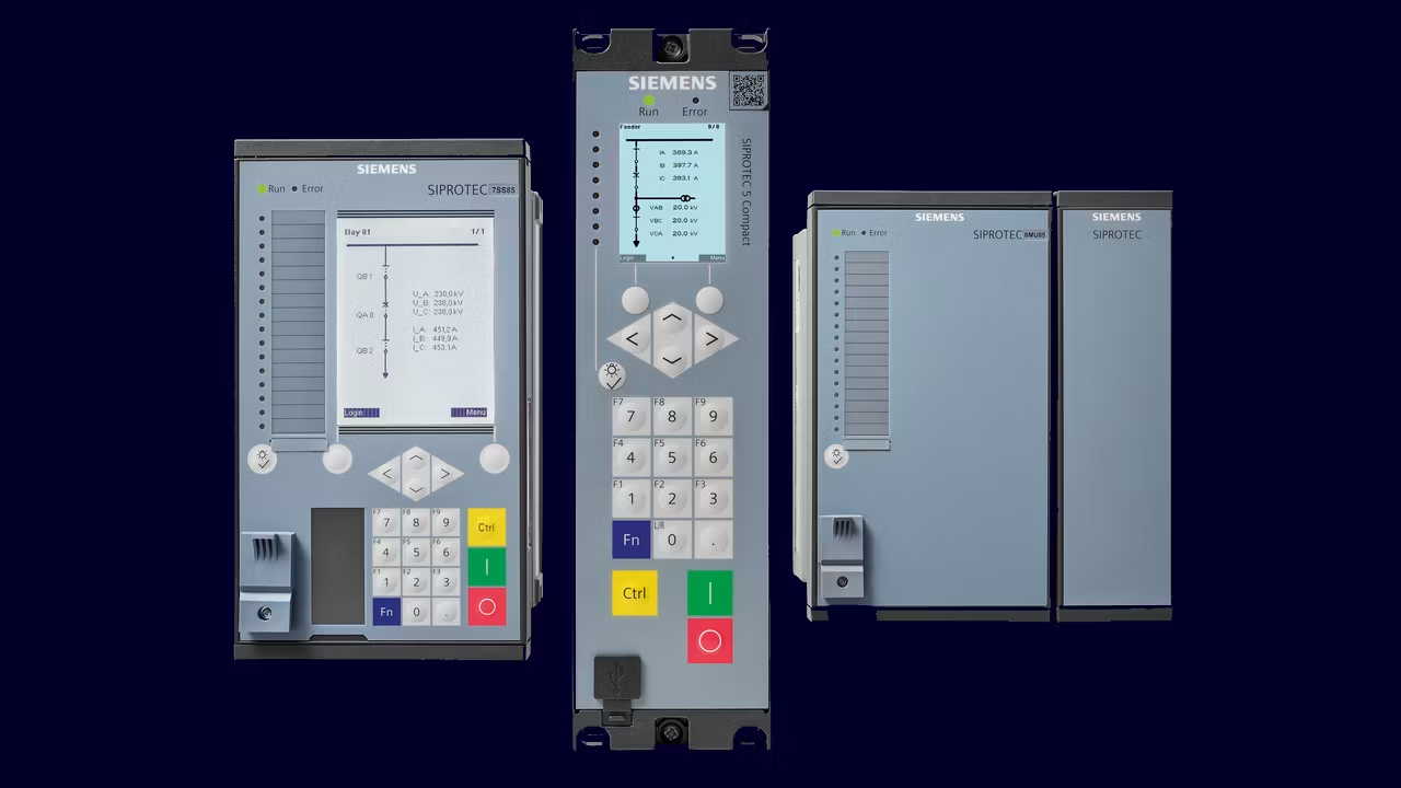
siprotec 5 2
Siemens Siprotec 5 Protection Relay

Advanced Technical Capabilities

SIPROTEC 5 introduces several important technical advancements:

  • IEC 61850 Edition 2 Support: The series provides native support for both station bus and process bus communication according to IEC 61850-8-1 and IEC 61850-9-2. Siemens was the first manufacturer to receive the IEC 61850 Edition 2 Certificate Level A¹, confirming its leadership in substation automation standards.
  • Integrated Phasor Measurement Unit (PMU): Many devices include built-in synchrophasor measurement according to IEEE C37.118, enabling wide-area monitoring and improved grid stability analysis.
  • Wide Frequency Tracking: Protection functions remain accurate across a frequency range of 10 Hz to 80 Hz. This capability is particularly valuable in networks with high penetration of renewable energy sources where frequency variations can be significant.
  • Advanced Cybersecurity: The platform incorporates comprehensive security features, including role-based access control (RBAC), signed firmware, TLS encryption, and IEEE 802.1X network authentication, helping utilities meet increasing cybersecurity requirements.
  • Process Bus Readiness: Direct connection to merging units and support for sampled values allow for fully digital substation architectures.

Engineering and Digital Tools

SIPROTEC 5 is supported by a complete set of modern engineering and diagnostic tools. DIGSI 5 serves as the central engineering software, providing an intuitive interface for configuration, testing, and maintenance. The SIPROTEC DigitalTwin enables virtual testing of relay behavior before physical commissioning, reducing risks and project timelines.

Additionally, the platform offers IoT and cloud connectivity through the OPC UA PubSub protocol. This allows direct integration with cloud platforms such as Siemens MindSphere and supports advanced monitoring applications through the SIPROTEC Dashboard.

Main Device Families in SIPROTEC 5

The SIPROTEC 5 portfolio covers a wide range of protection and control applications:

  • Overcurrent and Feeder Protection: Devices such as 7SJ81, 7SJ82, and 7SJ85 provide directional and non-directional overcurrent protection along with earth fault and thermal overload functions.
  • Distance Protection: The 7SA82, 7SA86, and 7SA87 models deliver high-speed distance protection with teleprotection schemes and automatic reclosing.
  • Line Differential Protection: Models including 7SD82, 7SD86, and 7SD87 offer selective protection for overhead lines and cables with charging current compensation.
  • Transformer Differential Protection: The 7UT82 to 7UT87 series provides fast and reliable differential protection for two-winding and multi-winding transformers.
  • Motor and Generator Protection: Specialized devices such as 7SK82, 7SK85, and 7UM85 ensure comprehensive protection for rotating machines.
  • Busbar Protection: The 7SS85 offers distributed busbar differential protection with high speed and selectivity.
  • Bay Controllers and Merging Units: Devices like 6MD85, 6MD86, and 6MU85 support advanced control and process bus applications.
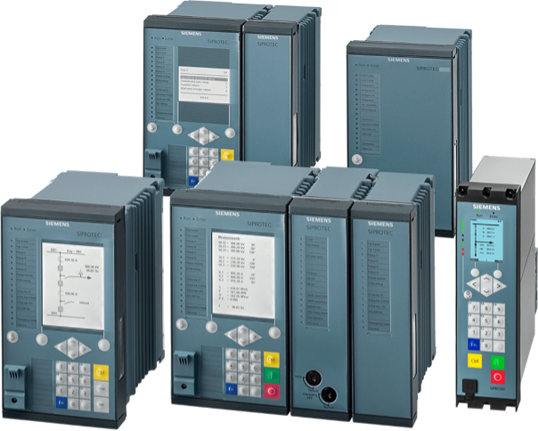
siprotec 5 relay
Siemens Siprotec 5 Protection Relays

Benefits for Modern Power Systems

Siemens SIPROTEC 5 is particularly well suited for today’s evolving power grids. Its wide frequency range, integrated PMU functionality, and strong cybersecurity features address the specific challenges created by renewable energy integration and digital substation architectures. The modular design also supports long-term standardization across different voltage levels and applications, simplifying training and maintenance for operating personnel.

Looking for Siemens SIPROTEC for your project?

Looking for advanced Siemens SIPROTEC 5 protection relays, modular solutions, process bus applications, or complete substation automation systems? We provide expert technical support and genuine Siemens SIPROTEC products for all medium, high, and extra-high voltage applications.

For quotations and requests: info@electricistanbul.com

Whatsapp: +90 501 076 69 91
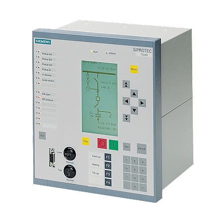
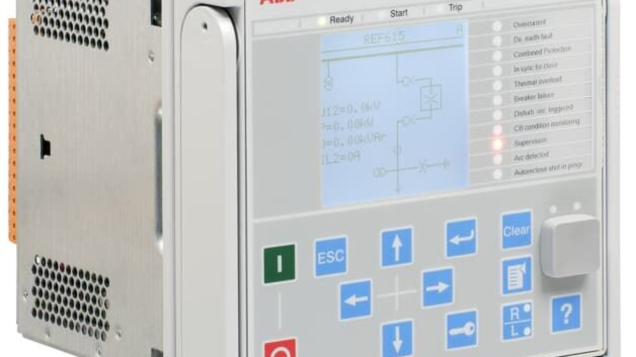
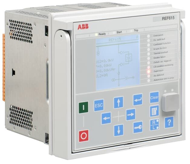
abb ref 615

ABB REF615 Protection Relay – Advanced Feeder Protection and Control Solution

ABB REF615 Protection Relay – Advanced Feeder Protection and Control Solution

The ABB REF615 is a compact and powerful feeder protection and control relay belonging to ABB’s Relion 615 series. It is specifically designed for the protection, control, measurement, and supervision of overhead lines and cable feeders in utility substations and industrial power distribution systems. As a member of the ABB protection relay family, the REF615 offers high performance in both main protection and backup protection applications.

This relay is suitable for radial, looped, and meshed distribution networks, including systems with distributed generation. Its withdrawable design and support for the IEC 61850 standard with GOOSE messaging make it a modern and flexible solution for today’s medium voltage networks.

abb ref 615 2
ABB REF615 Protection Relays

Key Features of ABB REF615 Protection Relay

The ABB REF615 stands out with its compact size and advanced functionality. It comes with multiple pre-configured standard versions (from configuration A to J), allowing users to select the most suitable version according to their specific application requirements.

One of the major advantages of the REF615 is its withdrawable design. This feature significantly reduces maintenance time and allows quick replacement without extensive rewiring. The relay also includes a clear and user-friendly local human-machine interface (HMI), which simplifies operation and monitoring in the field.

The ABB REF615 supports a wide range of protection functions, including non-directional and directional overcurrent protection, earth fault protection, thermal overload protection, voltage protection, and frequency protection. It also offers advanced capabilities such as disturbance recording, event logging, condition monitoring, and arc flash protection. These features help improve both system reliability and personnel safety in medium voltage installations.

Protection and Control Capabilities

As a dedicated feeder protection relay, the ABB REF615 provides comprehensive protection for medium voltage feeders. It can detect and isolate faults quickly, minimizing damage to equipment and reducing outage times. The relay supports both main protection and backup protection schemes, making it suitable for critical applications where redundancy is required.

In addition to basic overcurrent and earth fault protection, the REF615 includes functions for load encroachment, broken conductor detection, and sensitive earth fault protection. These advanced features allow for more precise fault detection and better coordination with other protective devices in the network.

The relay also offers control functions for circuit breaker and disconnector operation, along with interlocking logic to ensure safe switching operations. This combination of protection and control in a single device helps reduce panel space and simplifies system design.

Communication and Configuration

The ABB REF615 fully supports the IEC 61850 communication standard, including GOOSE messaging for fast peer-to-peer communication between intelligent electronic devices (IEDs). It also supports other widely used protocols such as Modbus, DNP3, and IEC 60870-5-103, providing flexibility for integration into both new and existing substation automation systems.

Configuration and engineering of the relay are performed using ABB’s PCM600 software. This powerful tool allows engineers to easily set protection parameters, create logic, and manage relay settings across multiple devices. The software also supports testing and commissioning activities, helping reduce engineering time and potential errors.

abb ref 615
ABB REF615 Protection Relay

ABB 615 Series – Complete Protection Portfolio

The ABB REF615 is part of the broader Relion 615 series, which offers dedicated protection relays for different applications:

  • REF Series: Feeder protection (including REF615)
  • RET Series: Transformer protection (RET615, RET620, RET630)
  • REM Series: Motor protection (REM615, REM620, REM630)
  • REG Series: Generator protection
  • REB Series: Busbar protection
  • REV Series: Capacitor and filter bank protection
  • REU Series: Voltage protection and control
  • REC Series: Remote monitoring and control
  • REX640: Advanced substation automation and protection

This wide portfolio allows users to select the most appropriate relay for each application while maintaining a consistent engineering and communication platform across the substation.

ABB REF615 in Modern Power Systems

The ABB REF615 is widely used in utility distribution substations, industrial plants, renewable energy connections, and infrastructure projects. Its compact design, high functionality, and strong communication capabilities make it an excellent choice for both new installations and retrofit projects where space and performance are important considerations.

With its support for arc flash protection and advanced monitoring features, the REF615 also contributes to improved safety and reduced maintenance costs. The relay’s ability to operate reliably in various network configurations, including those with distributed generation, makes it well-suited for modern power systems.

Looking for ABB Protection Relay for your project?

Looking for high-performance ABB protection relay, ABB REF615, or complete solutions including ABB distance protection relay for feeder, transformer, motor, or generator protection? We provide expert technical support and genuine ABB products tailored to your medium voltage requirements.

For quotations and requests: info@electricistanbul.com

Whatsapp: +90 501 076 69 91

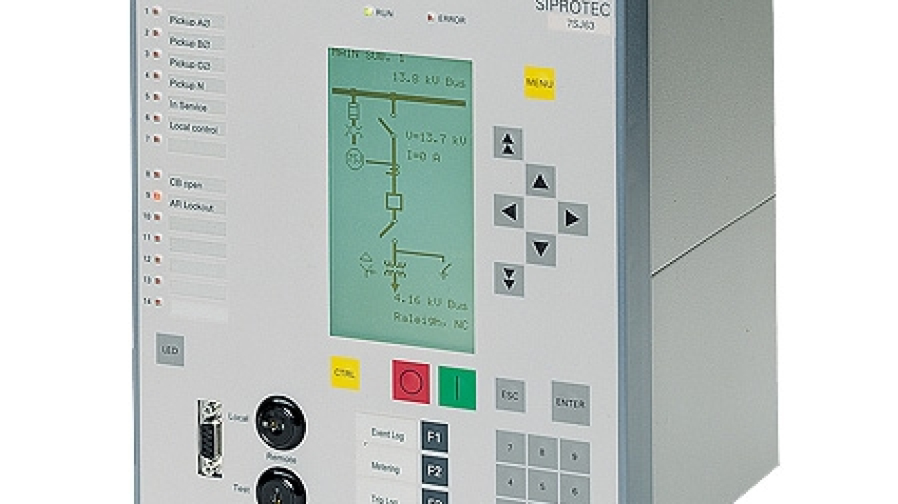
siprotec 4

Siemens SIPROTEC 4 Protection Relays – Proven Numerical Protection Technology

Siemens SIPROTEC 4 Protection Relays – Proven Numerical Protection Technology

Siemens SIPROTEC 4 is one of the most successful and widely deployed families of numerical protection relays in the world. With more than one million devices installed across power generation, transmission, and distribution networks, the SIPROTEC 4 series has established itself as a reliable and versatile platform for medium and high voltage applications.

This series integrates protection, control, measurement, and automation functions into a single compact device. It was developed to meet the increasing demands of modern power systems while maintaining the high reliability that utilities and industrial users expect from Siemens protection technology.

Core Design Philosophy of SIPROTEC 4

The fundamental strength of SIPROTEC 4 lies in its “one feeder – one relay” concept. Instead of using multiple separate devices for protection, control, and monitoring, a single SIPROTEC 4 relay can perform all these tasks. This approach significantly reduces engineering effort, wiring complexity, and panel space requirements.

All devices in the series are built on a common hardware and software platform. This uniformity simplifies training, spare parts management, and system maintenance. The relays are designed according to IEC 61850 standards and support GOOSE messaging, enabling fast and reliable communication between intelligent electronic devices in substation automation systems.

siprotec 5 relay
Siemens Siprotec 4 Protection Relay Family

Key Technical Features

SIPROTEC 4 relays offer several advanced technical capabilities:

  • Integrated Protection and Control: Each device combines multiple protection functions with bay control, measurement, and automation logic in one unit.
  • Powerful CFC Logic: The Continuous Function Chart (CFC) tool allows users to create custom automation and interlocking schemes without requiring external programmable logic controllers.
  • Comprehensive Fault Recording: The relays can record analog and binary signals for several seconds. This feature is particularly useful for post-fault analysis and protection coordination studies.
  • Self-Monitoring System: Continuous supervision of hardware, software, current and voltage transformer circuits, and trip coil circuits ensures high availability and early detection of potential problems.
  • Flexible Hardware Design: Available in 1/3, 1/2, and 1/4 of 19-inch housings. Some models feature withdrawable designs and detachable operator panels, making maintenance and testing more convenient.
  • User-Friendly HMI: The local interface includes a backlit LCD display, freely assignable LEDs, function keys, and a numerical keypad. This allows operators to perform many tasks without connecting a laptop.

Popular Models in the SIPROTEC 4 Family

The SIPROTEC 4 series includes several specialized models for different applications:

  • 7SJ61, 7SJ62, 7SJ63, 7SJ64, and 7SJ66: These are multifunction feeder and motor protection relays widely used for overcurrent, earth fault, and thermal protection.
  • 7SA6 and 7SA522: Distance protection relays designed for overhead lines and cables, offering fast and selective fault clearance.
  • 7UT6 Series: Transformer differential protection relays that can also be applied for generator, motor, and busbar differential protection.
  • 7UM61 and 7UM62: Specialized generator and motor protection relays with comprehensive functions for synchronous machines.

These models cover the majority of protection requirements in medium and high voltage networks while maintaining consistent engineering and communication interfaces.

Engineering and Configuration with DIGSI 4

One of the major advantages of the SIPROTEC 4 platform is the DIGSI 4 engineering software. This powerful tool provides a unified environment for parameter setting, logic programming, testing, and fault analysis. Engineers can manage the entire protection system from a single software platform, which improves efficiency and reduces the risk of configuration errors.

The software also supports four independent setting groups that can be switched locally or remotely. This feature is particularly useful in networks with changing operating conditions or seasonal load variations.

siprotec 4
Siemens Siprotec 4 Protection Relay

Communication Capabilities

SIPROTEC 4 relays support a wide range of communication protocols, including IEC 61850 (Edition 1 and 2), IEC 60870-5-103, PROFIBUS DP, Modbus RTU, and DNP 3.0. The communication modules are interchangeable, allowing users to adapt or upgrade the communication interface according to project requirements without replacing the entire relay.

This flexibility has made SIPROTEC 4 a popular choice for both new substations and retrofit projects where integration with existing systems is necessary.

Why SIPROTEC 4 Remains a Trusted Choice

Although newer platforms such as SIPROTEC 5 have been introduced, the SIPROTEC 4 series continues to be widely used due to its proven field performance, extensive application experience, and long-term availability of spare parts. Many utilities and industrial users continue to standardize on SIPROTEC 4 for medium voltage applications because of its reliability, ease of engineering, and cost-effectiveness.

The combination of robust hardware, comprehensive protection functions, and powerful engineering tools has made Siemens SIPROTEC 4 a benchmark in numerical protection technology for more than two decades.

Looking for Siemens SIPROTEC for your project?

Looking for reliable Siemens SIPROTEC, SIPROTEC 4, SIPROTEC 7SJ61, SIPROTEC 7UM62, or complete protection solutions with SIPROTEC DIGSI? We provide expert technical support and genuine Siemens products for all your medium and high-voltage applications.

For quotations and requests: info@electricistanbul.com

Whatsapp: +90 501 076 69 91