
“`
Switchgear maintenance is the planned combination of visual inspection, mechanical checks, and electrical diagnostic testing (contact resistance, insulation resistance, partial discharge, timing tests) performed on medium-voltage switchgear at defined intervals to verify that it will continue to interrupt fault current and isolate circuits safely for the remainder of its service life. This guide sets out the first-principles logic behind maintenance intervals and pass/fail criteria, walks through a worked contact-resistance and thermal-loss calculation, and compares condition-based versus time-based strategies for buyers and asset managers across the Middle East and Gulf region (including Egypt and Saudi Arabia), North Africa, the CIS, and Sub-Saharan Africa, where harsh ambient conditions (dust, humidity, high temperature) accelerate degradation relative to temperate climates.
Unlike a datasheet, this article does not rate any specific breaker or ring main unit — it explains the engineering method any qualified maintenance engineer applies to any MV switchgear, referencing the relevant IEC/IEEE framework so the logic can be applied consistently regardless of manufacturer.
Why maintenance strategy matters
A circuit breaker or switch-disconnector that has operated correctly for ten years is not guaranteed to interrupt the next fault current correctly if its contacts have eroded, its operating mechanism has stiffened due to lubricant hardening, or its insulation has absorbed moisture. Because MV switchgear typically switches infrequently (a ring main unit may see only a handful of operations per year) but must perform flawlessly the one time a real fault occurs, maintenance is fundamentally a risk-of-hidden-failure problem rather than a wear problem in the classic mechanical sense. The engineering task is therefore to schedule inspections and tests frequently enough to catch degradation trends before they cross a failure threshold, without over-maintaining (which itself introduces intervention risk through unnecessary opening of sealed compartments).
This is the same logic used for protection relays and transformers — see our related guides on protection relay coordination and distribution transformer sizing for how those asset classes fit into the same reliability framework.
The method: condition indicators and their governing formulas
Three quantities dominate MV switchgear condition assessment:
1. Contact (loop) resistance, R. Rising resistance across a bus joint, breaker contact, or cable termination indicates oxidation, loosening, or erosion. The diagnostic quantity is the power dissipated at rated current:
P_loss = I² × R
A small increase in R produces a large increase in localized heating because loss scales with the square of current — this is why contact resistance testing at rated or test current is far more sensitive than a simple visual check.
2. Insulation resistance (IR) and polarization index (PI). Insulation resistance is measured with a DC megohmmeter at a specified test voltage; the polarization index is the ratio:
PI = IR(10 min) / IR(1 min)
A PI trending downward over successive tests indicates moisture ingress or insulation aging even if the absolute IR value still appears acceptable.
3. Mechanical operating time and travel. For circuit breakers, opening/closing time and contact travel are checked against the manufacturer’s reference curve; a shift indicates worn linkages, degraded spring energy, or a sluggish operating mechanism — all of which can delay fault clearance and increase the let-through energy (I²t) seen by downstream equipment.
Worked example: contact resistance and thermal loss at rated current
Step 1 — establish rated current. For example, a 1000 kVA, 11 kV transformer’s HV-side rated current is:
I = S / (√3 × V) = 1,000,000 / (1.732 × 11,000) ≈ 52.5 A
This is the current level at which the upstream ring main unit’s switch-disconnector or breaker contact is expected to carry continuous load.
Step 2 — baseline vs. degraded contact resistance. Suppose a factory-new contact joint measures R₁ = 50 µΓ (0.00005 Ω) during commissioning micro-ohmmeter testing, and after several years in a dusty coastal environment the same joint measures R₂ = 150 µΩ (0.00015 Ω) — a threefold increase, a plausible and commonly-cited trigger for corrective action in maintenance practice.
Step 3 — compute dissipated power at rated current for both cases:
P₁ = I² × R₁ = (52.5)² × 0.00005 ≈ 2,756 × 0.00005 ≈ 0.138 W P₂ = I² × R₂ = (52.5)² × 0.00015 ≈ 2,756 × 0.00015 ≈ 0.413 W
Step 4 — interpret. The power dissipated at the joint has roughly tripled, matching the resistance increase (since P scales linearly with R at fixed I). While 0.4 W may look trivial in isolation, this loss is concentrated in a small metallic contact area with limited surface for convective cooling inside a sealed cubicle — local hot-spot temperature rise is what actually damages the contact plating and accelerates further oxidation, a self-reinforcing degradation loop. This is exactly why contact-resistance test results are trended over time rather than judged against a single absolute pass/fail number: the rate of change reveals the degradation curve before a hot spot becomes visible thermographically or, worse, becomes a fault.
Step 5 — cross-check with a fault-current scenario. If a downstream fault forces a much higher current momentarily through the same degraded joint — say a short-circuit current of 20 kA for a duration governed by protection clearing time — the instantaneous loss would be:
P_fault = I² × R₂ = (20,000)² × 0.00015 = 4 × 10⁸ × 0.00015 = 60,000 W (60 kW)
even for a fraction of a second. This illustrates why a degraded contact that is thermally “fine” under normal load current can fail catastrophically under fault conditions — the I² term punishes any resistance increase disproportionately at high current, which is the core justification for periodic contact-resistance testing rather than relying on load-current thermography alone.
Maintenance interval and test comparison table
| Task | Typical trigger / basis | Diagnostic quantity | Engineering rationale |
|---|---|---|---|
| Visual/thermographic inspection | Time-based (routine) | Surface temperature, visible corrosion/tracking | Detects gross hot spots and contamination before failure |
| Contact resistance (micro-ohmmeter) | Time-based or after fault-current interruption | R (µΩ), trended vs. baseline | Directly linked to I²R heating risk shown above |
| Insulation resistance / PI test | Time-based, or after moisture exposure | IR (MΩ), PI ratio | Flags moisture ingress and insulation aging |
| Mechanism timing / travel test | Time-based, or after high operation count | Opening/closing time, travel curve | Confirms fault-clearing speed is unchanged |
| SF6/vacuum interrupter integrity check | Time-based (where applicable) | Pressure/vacuum level | Confirms interrupting medium is intact |
| Partial discharge (PD) survey | Condition-based, online where possible | PD magnitude/pattern | Non-intrusive early warning of insulation defects |
| Protection relay functional test | Coordinated with switchgear outage | Pickup/trip time vs. setting | Confirms breaker + relay act together as designed |
The right-hand column matters more than any single number: every test exists to answer “will this device still interrupt correctly and stay insulated?” — not to produce a certificate.
Selection criteria for a maintenance strategy, and common pitfalls
- Time-based vs. condition-based. Time-based (calendar or operation-count) intervals are simpler to plan but can under- or over-maintain equipment whose actual degradation depends on load history and ambient conditions. Condition-based maintenance, informed by trended contact-resistance, PI, and (where available) online partial-discharge or temperature monitoring, aligns intervention with actual degradation rate — the approach favored by IEC/IEEE-aligned reliability-centered maintenance (RCM) programs.
- Environment-adjusted intervals. Installations in hot, dusty, or high-humidity environments — common across Gulf, North African, and Sub-Saharan sites — typically warrant shortened inspection intervals relative to indoor, climate-controlled substations, because contamination and thermal cycling accelerate both contact oxidation and insulation aging.
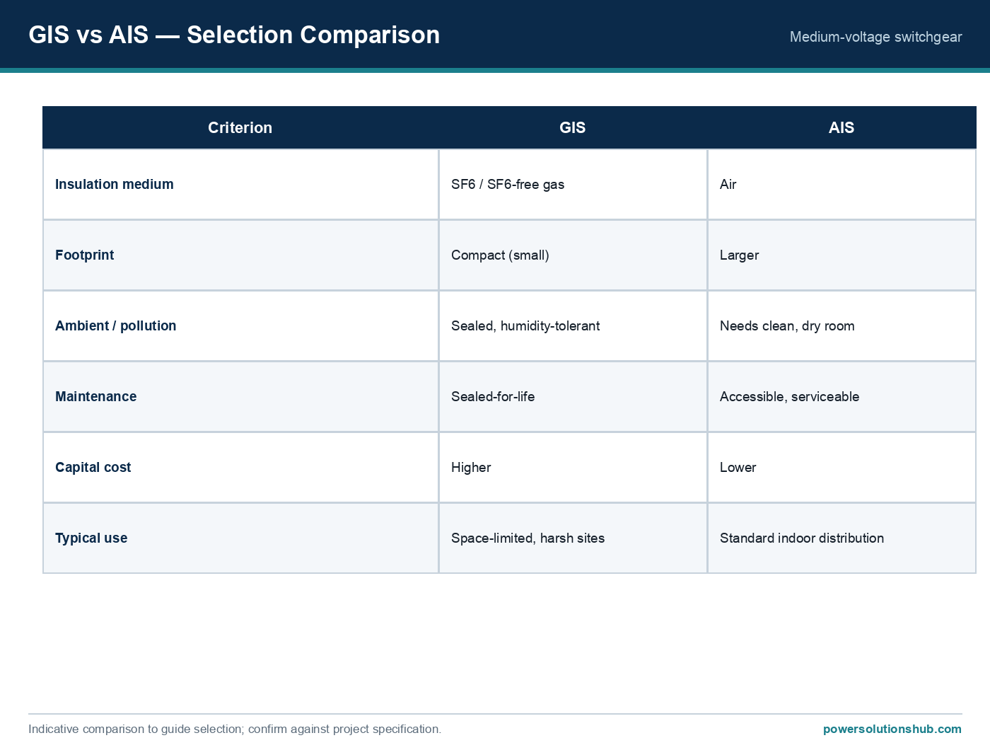
- Sealed-for-life and cast-resin equipment. Sealed-for-life switchgear (e.g., SF6-insulated or solid-dielectric compartments) and cast-resin components are designed to reduce the need for internal intervention, shifting the maintenance emphasis toward external monitoring (thermography, PD survey) rather than opening compartments, which itself introduces contamination risk.
- Common pitfall — testing at the wrong current. Measuring insulation resistance or contact resistance at a voltage/current far below rated conditions can mask a defect that only manifests under load or fault stress; test procedures should follow manufacturer and IEC test-voltage guidance.
- Common pitfall — ignoring trend data. A single “acceptable” reading is far less informative than the trend across several maintenance cycles; the worked example above shows why a threefold resistance increase is significant even if the absolute value still appears “low.”
- Common pitfall — decoupling breaker and relay maintenance. A perfectly maintained breaker with a mis-set or untested protection relay still fails to clear faults within the assumed time, invalidating downstream coordination studies — breaker and relay maintenance should be scheduled together.
Governing standards
MV switchgear maintenance practice is generally referenced against the IEC 62271 series covering high-voltage switchgear and controlgear (including guidance on operation and maintenance considerations for AC circuit breakers and switching devices), alongside IEEE guidance such as IEEE C37 series recommended practices for circuit breaker maintenance and testing in North American-influenced markets. Insulation and dielectric testing practices commonly reference IEC 60060 for high-voltage test techniques. Site-specific maintenance programs should always be read together with the equipment manufacturer’s instruction manual, since permissible test voltages, torque values, and interval recommendations are equipment-specific.
Related guides
See also our guides on gas-insulated switchgear, metal-clad switchgear and air-insulated switchgear.
How often should MV switchgear be inspected?
There is no single universal number — intervals depend on equipment type (sealed-for-life vs. air-insulated), ambient environment, and load/fault history. Manufacturers publish reference intervals, and condition-based programs adjust these using trended test data rather than a fixed calendar alone.
What is contact resistance testing and why does it matter?
It measures the micro-ohm-level resistance across a joint or contact using a micro-ohmmeter. Because dissipated power scales with the square of current (P = I²R), even a small resistance increase becomes significant heating risk at rated or fault current, as shown in the worked example above.
What does a falling polarization index (PI) indicate?
A PI trending downward across successive tests typically indicates moisture ingress or progressive insulation aging, even if the absolute insulation resistance value still passes a single-test threshold.
Can switchgear maintenance be done without a full outage?
Some diagnostics — infrared thermography and online partial-discharge surveys — can be performed with the switchgear energized and in service. Internal inspection, contact-resistance testing, and mechanism timing tests generally require the circuit to be de-energized and isolated.
Is sealed-for-life switchgear maintenance-free?
No — “sealed-for-life” reduces the need for internal servicing of the interrupting medium, but external checks (thermography, mechanism function, protection coordination) are still required over the equipment’s service life.
How does switchgear maintenance relate to protection relay testing?
Fault clearing depends on both the breaker interrupting correctly and the relay tripping at the correct setting and time. Maintenance programs should test them together so that coordination studies remain valid.
What standards govern MV switchgear maintenance?
The IEC 62271 series for high-voltage switchgear and controlgear provides the general framework, often supplemented by IEEE C37 series practices and IEC 60060 for dielectric test methods; manufacturer instructions take precedence for equipment-specific values. “`
Looking for medium voltage switchgear?
Looking for high-quality medium voltage switchgear? We provide expert engineering support and reliable products for all your medium voltage needs.
For quotations and requests: info@electricistanbul.com
WhatsApp: +90 501 076 69 91