Motor Control Center (MCC) Guide

Motor Control Center (MCC) Guide: Sizing, Calculations & Selection

A motor control center (MCC) is a factory-assembled switchgear and controlgear assembly housing multiple motor feeder units — each combining an isolator, a contactor or circuit breaker, overload protection, and control wiring — within a common enclosure fed from a shared busbar, used to start, protect, and control groups of electric motors in industrial and utility plants. This guide walks through the first-principles calculations an engineer needs before specifying an MCC: full-load current (FLC), starting current, short-circuit withstand, and busbar sizing with diversity, followed by selection criteria and the governing IEC standards. The guidance applies equally to projects across the Middle East and Gulf (including Egypt and Saudi Arabia), North Africa, the CIS region, and Sub-Saharan Africa, where ambient temperature, dust ingress, and grid fault levels strongly influence MCC design margins.
Motor Control Center (MCC) Guide — schematic
Motor Control Center (MCC) Guide — schematic.

Why MCC sizing matters

An undersized MCC busbar or starter will nuisance-trip or, worse, fail to withstand a downstream short circuit; an oversized one wastes capital. The three calculations every specifier must perform are:

  1. Motor full-load current (FLC) — sets the minimum rating of the contactor, overload relay, and feeder cable.
  2. Starting current — determines inrush withstand, voltage-dip impact, and the choice of starting method (DOL, star-delta, soft starter, or VFD).
  3. Prospective short-circuit current at the MCC busbar — sets the required breaking/withstand rating of the incomer and feeder devices, coordinated with the upstream transformer and protection relay settings (see our protection relay guide for relay coordination basics).
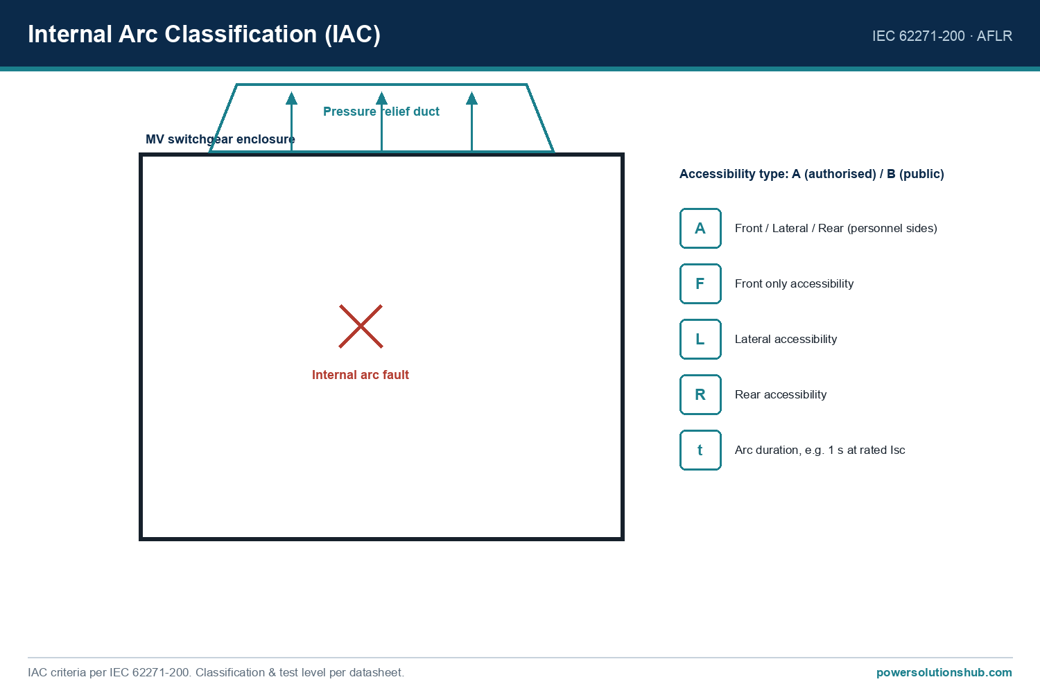
Selection reference
Selection reference.

The method / formula

Three-phase motor full-load current:

I_FLC = P / (√3 × V × PF × η)

Where P = motor shaft output power (W), V = line voltage (V), PF = power factor, η = efficiency.

Starting current is expressed as a multiple of FLC, depending on the starting method:

I_start = k × I_FLC

Prospective short-circuit current at a busbar fed through a transformer of known impedance:

I_rated(transformer) = S / (√3 × V) I_sc ≈ I_rated / Z%

After-diversity demand current for an MCC with multiple feeders:

I_demand = (Σ I_FLC,i) × Diversity Factor

These four formulas are sufficient to size an MCC’s feeder devices, incomer breaker, busbar, and required short-circuit rating before detailed vendor engineering begins.

Worked example with computed numbers

Step 1 — Motor FLC. For a 160 kW, 400 V three-phase motor with an assumed efficiency of 0.94 and power factor of 0.87:

I_FLC = 160,000 / (1.732 × 400 × 0.87 × 0.94) ≈ 160,000 / 566.6 ≈ 282.4 A

The feeder contactor, overload relay, and cable must each be rated at or above this value, with the overload relay typically set at roughly 1.15 × FLC ≈ 325 A to allow for normal service tolerance while still tripping on sustained overload.

Step 2 — Starting current. For a direct-on-line (DOL) start with an illustrative starting multiplier of 6 × FLC:

I_start = 6 × 282.4 ≈ 1,694 A

This inrush, even if brief, must be checked against upstream voltage-dip limits and against the withstand rating of the contactor and busbar during the starting transient. If the dip is unacceptable, the designer substitutes a star-delta starter (illustrative multiplier ≈ 2–3 × FLC) or a soft starter/VFD (illustrative multiplier below 2 × FLC) to reduce the inrush.

Step 3 — Short-circuit level at the MCC busbar. For a 1000 kVA transformer at 400 V with a nameplate impedance of 5%:

I_rated = 1,000,000 / (1.732 × 400) ≈ 1,443.4 A I_sc ≈ 1,443.4 / 0.05 ≈ 28,868 A ≈ 28.9 kA

The MCC incomer and busbar must therefore be specified with a short-circuit withstand/breaking rating equal to or greater than this computed prospective fault current, coordinated with the upstream transformer protection and the MCC’s own feeder breakers.

Step 4 — Busbar sizing with diversity. Suppose the MCC serves six motor feeders with a combined connected FLC of 1,200 A. Applying an illustrative diversity factor of 0.75 (not all motors run simultaneously at full load):

I_demand = 1,200 × 0.75 = 900 A

The incomer and main busbar would then be selected at the next standard rating above 900 A (e.g., 1,000 A), rather than at the full connected load of 1,200 A — avoiding unnecessary oversizing while retaining margin for future feeders.

Selection / comparison table

Parameter DOL starter Star-delta starter Soft starter Variable frequency drive (VFD)
Illustrative starting current multiplier ~6–8 × FLC ~2–3 × FLC ~2–4 × FLC <1.5 × FLC
Starting torque control None Stepped (transition bump) Smooth ramp Fully adjustable
Typical use case Small/medium motors, strong supply Medium motors, moderate supply stiffness Pumps, fans, conveyors needing soft start/stop Variable-speed process control
Relative panel space Lowest Low–medium Medium Highest
Harmonics on supply Negligible Negligible Low Requires filtering consideration

Figures above are illustrative engineering ranges for comparative teaching purposes, not ratings of any specific product.

Selection criteria & common pitfalls

  • Voltage class. Most MCCs operate at low voltage (≤1 kV) for motors up to a few hundred kW; large motors (several MW, typically above 1 kV) are switched via medium-voltage motor control centers using vacuum contactors or circuit breakers instead of LV contactors.
  • Form of internal separation. IEC 61439-2 defines Forms of separation (barriers between busbar, functional units, and terminals) — higher Forms improve personnel safety and limit fault propagation between feeders but increase cost and footprint.
  • Short-circuit withstand coordination. The MCC’s rated short-circuit withstand must be checked against the computed prospective fault current at its busbar (see worked example above), not assumed from a catalogue default.
  • Starting method vs. supply stiffness. DOL starting is simplest but produces the highest inrush and voltage dip; weak or long-feeder supplies may force a soft starter or VFD even for modest motor sizes.
  • Diversity and spare capacity. Sizing the incomer strictly off connected load (sum of FLCs) rather than after-diversity demand leads to oversized, costlier incomers; conversely, ignoring future motor additions leaves no spare feeder space.
  • Enclosure and ingress protection. In dusty, high-humidity, or coastal environments common across the Gulf, North Africa, and Sub-Saharan Africa, enclosure IP rating and internal climate control (heaters, filtered ventilation) should be reviewed against IEC 60529 ingress classes.
  • Overload and protection relay coordination. Overload relay and feeder breaker settings must coordinate with upstream protection relays and transformer fuses — see our protection relay guide for coordination fundamentals, and our switchgear hub for broader distribution-level coordination.

Standards

Motor control centers and their components are governed primarily by:

  • IEC 61439-1 and IEC 61439-2 — general rules and particular requirements for low-voltage switchgear and controlgear assemblies, covering Forms of separation, temperature rise, and verification of assemblies such as MCCs.
  • IEC 60947-4-1 — requirements for contactors and motor-starters, including overload relay coordination categories.
  • IEC 62271-106 — requirements for high-voltage alternating-current contactors, relevant to medium-voltage motor control centers switching large motors.
  • IEC 60529 — degrees of protection (IP codes) for enclosures.

Where a project specifies a different or national standard (e.g., an equivalent NEMA ICS framework), the underlying sizing calculations shown above remain the same; only verification and test procedures differ.

Related guides

See also our guides on medium voltage switchgear, gas-insulated switchgear and ring main units.

What is the difference between an MCC and a switchgear lineup?

A switchgear lineup typically distributes power to outgoing feeders (cables, transformers, other panels), while an MCC is purpose-built around motor starting and protection, combining isolators, starters/contactors, and overload devices for multiple motor feeders in one assembly.

How do I choose between a soft starter and a VFD?

Choose a soft starter when only a smooth start/stop is needed without continuous speed control; choose a VFD when the process requires variable speed operation, energy savings at part load, or precise torque/speed control throughout the run cycle.

Why does the overload relay setting differ from the motor FLC?

The overload relay is normally set slightly above the calculated FLC (commonly around 1.1–1.2 times FLC) to accommodate normal service tolerances while still tripping reliably on a genuine sustained overload condition.

What causes an MCC busbar to be undersized in practice?

The most common cause is sizing the incomer and busbar from the raw sum of connected motor FLCs without applying a diversity factor, or failing to recompute the prospective short-circuit current after a transformer upgrade.

Is a medium-voltage MCC different from a low-voltage MCC?

Yes — low-voltage MCCs use contactors and circuit breakers for motors below roughly 1 kV, while medium-voltage MCCs use vacuum contactors or MV circuit breakers for large motors operating above 1 kV, with different insulation and arc-management requirements.

How does ambient temperature affect MCC sizing in hot climates?

High ambient temperatures reduce the current-carrying capacity of busbars, cables, and contactors, so derating factors must be applied in Gulf, North African, and Sub-Saharan African installations where enclosure internal temperatures can exceed temperate-climate design assumptions.

Which IEC standard should I ask a vendor to certify an MCC against?

Request compliance verification to IEC 61439-1/61439-2 for the assembly itself, and IEC 60947-4-1 for the individual contactors and motor-starters installed within it.

Looking for motor control centers and soft starters?

Looking for high-quality motor control centers and soft starters? We provide expert engineering support and reliable products for all your medium voltage needs.

For quotations and requests: info@electricistanbul.com

WhatsApp: +90 501 076 69 91
Soft Starter vs VFD vs DOL Starting

Soft Starter vs VFD vs DOL Starting: Engineering Comparison & Calculation Guide

A motor starting method — direct-on-line (DOL), soft starter, or variable frequency drive (VFD) — is the control strategy used to energize an induction motor while managing inrush current, mechanical torque shock, and voltage disturbance on the supply network. The right choice affects switchgear sizing, cable sizing, transformer loading, and the service life of driven mechanical equipment. This guide walks through the underlying formulas, a fully worked numeric example, and a side-by-side comparison to help engineers and procurement teams specify the correct starting method for pumps, fans, compressors, and conveyors across industrial and utility projects, including installations in the Middle East and Gulf (including Egypt and Saudi Arabia), North Africa, CIS, and Sub-Saharan Africa.

Soft Starter vs VFD vs DOL Starting — schematic
Soft Starter vs VFD vs DOL Starting — schematic.

Why Starting Method Selection Matters

When an induction motor is switched directly across the line, it draws a starting current many times its full-load current (FLC) because, at standstill, the rotor behaves almost like a short-circuited transformer secondary. This inrush:

  • Causes voltage dip on the upstream busbar, which can affect other connected loads and protection relay settings.
  • Produces a high starting torque transient that stresses couplings, belts, gearboxes, and pump shafts.
  • Forces upstream transformers, cables, and switchgear/protection devices to be sized for the momentary current rather than the steady-state load.

Soft starters and VFDs were developed specifically to reduce this inrush and torque shock by controlling voltage or frequency during acceleration, at the cost of additional equipment, panel space, and (for VFDs) harmonic considerations.

Selection reference
Selection reference.

The Method: How Each Starting Technique Works

DOL (Direct-On-Line): The motor is connected directly to full line voltage via a contactor or circuit breaker. Full voltage from t=0 means full magnetic flux and maximum starting current and torque from the first cycle.

Soft Starter: Back-to-back thyristors (SCRs) in each phase ramp the applied RMS voltage from a reduced starting level up to full voltage over a set time, following a closed-loop current-limit or voltage-ramp algorithm. Frequency stays fixed at supply frequency; only voltage magnitude is varied, which reduces both current and torque during acceleration but produces no speed control after start.

VFD (Variable Frequency Drive): A rectifier–DC bus–inverter stage synthesizes a variable-voltage, variable-frequency (V/f) output. Because the motor is fed near its rated V/f ratio from a very low starting frequency, the starting current can be limited close to full-load current while still developing adequate starting torque, and the drive continues to provide continuous speed control after acceleration.

Core Formulas

Starting current ratio for DOL is governed by the motor’s locked-rotor current multiplier, usually expressed as a ratio to full-load current:

I_start(DOL) = k_LR × I_FLC

where k_LR is the locked-rotor current multiplier (a nameplate/datasheet value for the specific motor).

For a soft starter operating in voltage-ramp or current-limit mode, the starting current is approximately proportional to the applied voltage ratio (since torque and current scale with roughly the square and the first power of voltage, respectively, for a given slip):

I_start(soft) ≈ (V_ramp / V_rated) × k_LR × I_FLC (current-limit mode caps this directly at a set multiple of I_FLC)

For a VFD, because the V/f ratio is kept nearly constant at low frequency, starting current is approximately bounded by the drive’s current limit setting, independent of the DOL locked-rotor multiplier:

I_start(VFD) ≈ I_limit_setting (typically close to I_FLC)

Full-load current itself, needed as the baseline for all three formulas, is derived from the motor’s rated power and voltage:

I_FLC = P / (√3 × V_L × cosφ × η) (three-phase motor, line quantities)

Worked Example: Comparing Starting Current for a 400 kW Motor

Assume a 400 kW, three-phase induction motor rated at 400 V, with efficiency η = 0.95, power factor cosφ = 0.88, and a locked-rotor current multiplier k_LR = 6 (a typical nameplate-style value used for illustration).

Step 1 — Full-load current:

I_FLC = P / (√3 × V_L × cosφ × η) I_FLC = 400,000 / (1.732 × 400 × 0.88 × 0.95) I_FLC = 400,000 / 579.5 I_FLC ≈ 690 A

Step 2 — DOL starting current:

I_start(DOL) = k_LR × I_FLC = 6 × 690 ≈ 4,140 A

Step 3 — Soft starter, voltage ramp at 50% initial voltage:

I_start(soft) ≈ (0.5) × k_LR × I_FLC = 0.5 × 6 × 690 ≈ 2,070 A

If the soft starter is instead configured in current-limit mode at, for example, 3 × I_FLC, the starting current is simply capped at:

I_start(soft, current-limit) = 3 × 690 ≈ 2,070 A

Step 4 — VFD starting current, limited to 1.5 × I_FLC:

I_start(VFD) = 1.5 × 690 ≈ 1,035 A

This worked example shows the same motor can draw roughly 4,140 A across the line, about 2,070 A with a soft starter, and only about 1,035 A with a VFD at the same drive current-limit setting — a direct illustration of why upstream cable, contactor, and protection relay sizing differs sharply between the three methods. (All figures above are computed for this illustrative example, not manufacturer ratings.)

Comparison Table: DOL vs Soft Starter vs VFD

Parameter DOL Soft Starter VFD
Starting current (typical multiple of I_FLC, illustrative) ≈6× (per k_LR example above) ≈2–3× (voltage-ramp/current-limit) ≈1–1.5× (current-limit setting)
Starting torque control None — fixed by motor design Adjustable via voltage ramp Fully adjustable via V/f or vector control
Speed control after start No No Yes, continuous
Mechanical shock on coupling/shaft Highest Reduced Lowest
Harmonic impact on supply Minimal Low (only during ramp) Requires harmonic mitigation (filters/multi-pulse)
Relative equipment cost & panel footprint Lowest Medium Highest
Typical application fit Small motors, stiff/strong grids Pumps, fans, compressors needing soft ramp only Processes needing variable speed/flow control

Selection Criteria & Common Pitfalls

  • Grid stiffness matters. On a weak feeder or a small transformer, even a soft starter’s reduced inrush may still cause a noticeable voltage dip; always check the available short-circuit level and transformer impedance before assuming a soft starter solves voltage-dip complaints.
  • Don’t confuse “soft start” with “speed control.” A soft starter only manages the acceleration ramp; once at full voltage it behaves like a DOL-connected motor. If the process needs continuous flow or pressure modulation, a VFD is required, not a soft starter.
  • Check torque, not just current. Reducing voltage with a soft starter reduces torque roughly with the square of the voltage ratio — verify the reduced-voltage torque still exceeds the load’s breakaway and acceleration torque curve (for pumps, fans, compressors, conveyors this varies widely).
  • Protection relay coordination. Starting current profiles differ sharply between DOL, soft starter, and VFD; motor protection relay thermal/overload curves and upstream circuit breaker settings must be coordinated to the actual starting method, not a generic assumption. See our protection relay guidance for coordination principles.
  • Harmonics and filtering. VFDs inject harmonic currents back into the supply; for larger drives or sensitive installations, line reactors, multi-pulse rectifiers, or active filters may be needed — factor this into switchgear and transformer design reviews.
  • Upstream equipment sizing. Transformer and [medium voltage switchgear](/what-is-mv-switchgear-medium-voltage-switchgear/) ratings, as well as cable sizing, should be checked against the actual chosen starting method’s current profile rather than worst-case DOL figures once a soft starter or VFD is confirmed in the design.
  • Transformer loading during starting. For motors fed from a dedicated MV/LV transformer, repeated DOL starts on an undersized transformer can cause excessive voltage dip and thermal cycling; soft starters or VFDs reduce this stress on the transformer winding and tap changer (where fitted).

Standards

Semiconductor-based soft starters for AC motors fall under IEC 60947-4-2 (low-voltage switchgear and controlgear — AC semiconductor motor controllers and starters). Variable frequency drives are covered by the IEC 61800 series, particularly IEC 61800-1 (general requirements for adjustable speed electrical power drive systems) and IEC 61800-3 (EMC requirements). Motor rated characteristics, including starting performance parameters referenced in the formulas above, are defined under IEC 60034-1 (rotating electrical machines — rating and performance). Project specifications should always confirm the applicable edition and any local grid code requirements for starting current and voltage-dip limits.

Related guides

See also our guides on gas-insulated switchgear, ring main units and metal-clad switchgear.

Is a soft starter cheaper than a VFD?

Yes, in general a soft starter has a lower equipment cost and smaller panel footprint than a VFD of equivalent motor rating, because it only manages the starting ramp rather than providing continuous variable-frequency output.

Can a soft starter control motor speed?

No. A soft starter only ramps voltage during starting and stopping; once at full voltage the motor runs at line frequency speed, same as a DOL-started motor. Continuous speed control requires a VFD.

Why does a VFD draw less starting current than DOL?

A VFD starts the motor at a very low frequency with a proportionally reduced voltage (constant V/f ratio), so the motor develops torque without the high magnetizing/locked-rotor current that occurs when full line voltage and frequency are applied instantaneously, as in DOL starting.

Does a soft starter reduce starting torque as well as current?

Yes. Because torque is approximately proportional to the square of applied voltage for a given slip, reducing the ramp voltage lowers starting torque significantly — this must be checked against the load’s breakaway torque requirement, as shown in the worked example section above.

When is DOL starting still acceptable?

DOL remains appropriate for small motors on a stiff grid where the resulting voltage dip and mechanical shock are within acceptable limits for the connected load and protection relay settings.

Do VFDs always need harmonic filters?

Not always, but larger VFDs or installations on sensitive or weak networks often require line reactors, multi-pulse rectifier configurations, or active filtering to meet IEC 61800-3 EMC limits and local grid code harmonic requirements.

How do I decide between a soft starter and a VFD for a pump application?

If the only requirement is a smooth start/stop to protect piping and check valves against water hammer, a soft starter is usually sufficient and more economical; if the process also needs continuous flow or pressure control at varying speeds, a VFD is the correct choice.

Looking for motor control centers and soft starters?

Looking for high-quality motor control centers and soft starters? We provide expert engineering support and reliable products for all your medium voltage needs.

For quotations and requests: info@electricistanbul.com

WhatsApp: +90 501 076 69 91
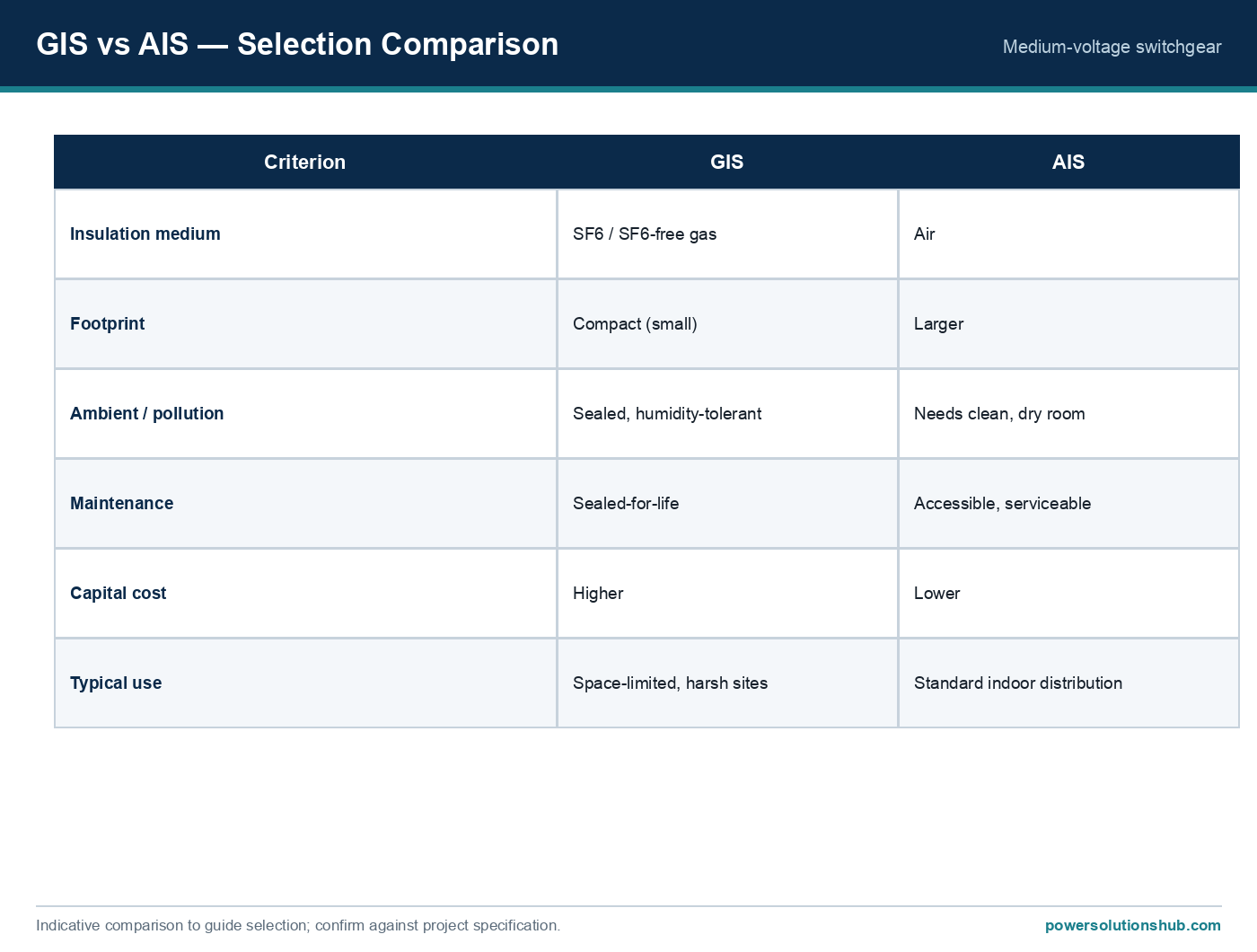
Stress Cone and Screen Bonding in MV Cable Terminations

Stress Cone and Screen Bonding in MV Cable Terminations: Calculation Guide

A stress cone cable termination is the component of a medium-voltage cable end-fitting that gradually enlarges the cut-back insulation screen interface to spread the electric field over a longer path, preventing localized dielectric breakdown or surface flashover at the point where the cable’s metallic screen is removed. This guide explains, from first principles and with worked numbers, why stress control geometry and correct screen/sheath bonding are inseparable parts of the same termination design problem, how to estimate the field reduction a stress cone provides, and how to size single-point versus cross-bonded screen arrangements. It is written for engineers specifying or commissioning MV terminations across export markets, including the Middle East and Gulf (incl. Egypt and Saudi Arabia), North Africa, CIS, and Sub-Saharan Africa, where cable routes often combine long single-core runs with mixed termination types at switchgear, transformers, and overhead-to-cable transitions.

Stress Cone and Screen Bonding in MV Cable Terminations — schematic
Stress Cone and Screen Bonding in MV Cable Terminations — schematic.

Why stress control and screen bonding matter together

A shielded MV cable is, electrically, a coaxial capacitor: the conductor is one electrode, the extruded or wire screen is the other, and the field between them is radial and well-behaved as long as the screen is continuous. The problem starts exactly where the screen is cut back to terminate the cable — the equipotential surface is interrupted, and the field lines that were radial now have to bend toward the exposed insulation surface. Without geometric control, this produces a sharp local concentration of tangential electric stress along the insulation surface, which is far more likely to initiate tracking or flashover than the normal radial stress the cable insulation is designed to withstand. The stress cone (capacitive or geometric) is the accessory that re-shapes this transition. Screen/sheath bonding is a separate but linked issue: once the screen is terminated, its grounding method determines what voltage appears on the screen itself during normal load and fault conditions, which in turn affects personnel safety at the termination and the design of any sheath voltage limiters (SVLs). A termination design is only complete when both the dielectric stress path and the screen bonding/grounding scheme have been checked.

Selection reference
Selection reference.

The method: electric field and stress-cone formulas

1. Radial field inside the cable insulation (coaxial approximation):

E(r) = U / [ r × ln(R/r) ]

Where U is the phase-to-ground voltage across the insulation, r is the radius from the cable axis to the point of interest, and R is the outer insulation radius (under the screen). This formula gives the “designed” stress the insulation sees everywhere the screen is intact — it is highest at the conductor screen (r = inner radius) and lowest at the outer screen.

2. Surface (creepage) stress at the screen cut-back:

Once the screen is removed over a length L at the termination, a simplified first-order model treats the voltage U as dropping along that exposed creepage path:

E_creep ≈ U / L

A short, abrupt cut-back gives a very short L and therefore a very high E_creep — this is the physical reason an unprotected cut screen is prone to flashover. A stress cone works by extending the effective transition length (and by capacitively grading the voltage along it), which lowers E_creep and brings the surface stress back down toward a tolerable range.

3. Induced sheath/screen voltage on single-point bonded systems:

For single-core cables run in parallel (trefoil or flat formation) with only one end of the screen grounded, the open end develops a standing voltage due to the mutual inductance between the phase conductor and its own screen:

Vs = I × X, with X = 2πf × (2×10⁻⁷) × ln(2S/d) [Ω/m]

Where I is the phase current, f is system frequency, S is the spacing between cable centers, and d is the diameter over the metallic screen/sheath. This voltage must stay within a level the termination’s insulation and any screen voltage limiter can safely handle, and within safe touch-voltage limits set by the applicable safety code.

Worked example

Part A — Stress cone benefit (illustrative, simplified model)

Take an 11 kV cable (phase-to-ground voltage Uo ≈ 6.35 kV), with insulation inner radius r = 7 mm (over conductor screen) and outer radius R = 12 mm (under the metallic screen).

Normal radial stress at the conductor screen (this is the stress the cable is designed for along its length):

E_normal = Uo / [r × ln(R/r)] = 6350 / [0.007 × ln(12/7)] = 6350 / [0.007 × 0.539] ≈ 1.68 × 10⁶ V/m ≈ 1.68 kV/mm

Now consider the termination. If the screen were cut back abruptly with almost no stress relief, assume an effective creepage length of only L = 20 mm:

E_creep (no stress cone) = Uo / L = 6350 / 0.020 ≈ 317.5 kV/m

That is roughly 190 times the cable’s own designed radial stress — clearly unsustainable and a classic cause of termination flashover.

With a stress cone extending the effective transition length to, say, L = 150 mm:

E_creep (with stress cone) = Uo / L = 6350 / 0.150 ≈ 42.3 kV/m

The stress cone in this illustrative model reduces the surface gradient by a factor of roughly 7.5×, bringing it back into a range the insulation surface and any field-grading (capacitive or geometric) layer can handle. (This is a simplified first-order model to illustrate the principle of stress-cone action, not a substitute for a manufacturer’s finite-element field design.)

Part B — Single-point bonded sheath voltage

Three single-core cables in trefoil, center spacing S = 0.15 m, diameter over the metallic screen d = 0.05 m, carrying I = 630 A at f = 50 Hz, over a route length of 500 m, single-point bonded (grounded at one end only).

X = 2πf × (2×10⁻⁷) × ln(2S/d) ln(2 × 0.15 / 0.05) = ln(6) = 1.792 2πf = 2 × 3.1416 × 50 = 314.16 X = 314.16 × 2×10⁻⁷ × 1.792 ≈ 1.126 × 10⁻⁴ Ω/m

Vs = I × X × length = 630 × 1.126×10⁻⁴ × 500 ≈ 35.5 V

At the open (ungrounded) end of this 500 m run, the sheath will stand at roughly 35 V above ground during normal load — a level that must be checked against the termination’s insulation and the enclosure’s touch-safety design, and against the rating of a sheath voltage limiter if one is fitted. Longer routes or higher currents raise this figure roughly linearly with length and current, which is why single-point bonding is normally restricted to shorter circuits, while longer circuits typically move to cross-bonding or both-ends bonding (with circulating-current trade-offs, see table below).

Comparison: screen/sheath bonding methods

Bonding method Sheath condition Circulating current Typical standing voltage Best suited for
Both-ends (solid) bonding Grounded at both ends Present (full circuit) — reduces standing voltage but adds I²R loss Near zero Short circuits where added losses are acceptable
Single-point bonding Grounded at one end only None (open circuit) Present at open end — see worked example Short-to-medium single-core runs, needs an SVL at the open end
Cross-bonding Screens transposed and grounded at both route ends Minimized by sheath transposition Low, balanced across sections Longer single-core circuits (multi-section routes)

Stress-control method comparison (qualitative)

Method Principle Typical installation context
Pre-molded (push-on) stress cone Factory-formed elastomeric cone slid over prepared cable end Fast, repeatable field installation
Heat-shrink stress control Heat-shrinkable stress-control tubing graded over the screen cut-back Flexible for varying cable diameters
Cold-shrink stress control Pre-stretched tube retracted onto the cable, no heat source needed Hazardous-area or no-flame installations
Hand-taped stress cone Built up manually with semi-conductive and insulating tapes Legacy or bespoke repair work, skill-dependent

Selection criteria and common pitfalls

  • Match the stress-control accessory to the cable insulation and screen type (extruded semi-conductive vs. wire screen vs. tape screen) — a stress cone designed for one screen construction will not grade the field correctly on another.
  • Verify creepage/leakage distance, not just the stress-cone length, against the termination’s pollution/environment class, particularly in coastal, desert-dust, or high-humidity GEO regions where surface contamination lowers the effective flashover voltage.
  • Decide the bonding scheme at the design stage, not at site — retrofitting cross-bonding after installation is costly. Use the induced-voltage formula above during design to check whether single-point bonding is adequate or whether a sheath voltage limiter and/or cross-bonding is required.
  • Do not omit the screen-to-ground connection even on “single-point” schemes — the ungrounded end still needs a properly rated SVL and insulated support to manage the standing voltage safely.
  • Coordinate the termination with upstream protection — a termination flashover looks electrically like a fault, so correct discrimination settings on the feeder relay are part of the overall system safety, alongside correct stress control. See our [protection relay](/what-is-a-medium-voltage-protection-relay-mv-protection-relay/) resources for coordination guidance.
  • Verify compatibility with the connected equipment — terminations feeding into [medium voltage switchgear](/what-is-mv-switchgear-medium-voltage-switchgear/) or medium voltage transformers must match the bushing/cable-box clearances and creepage requirements of that equipment, not just the cable’s own rating.

Standards

Cable accessories including stress cones and bonding arrangements for extruded MV cables are covered by IEC 60502-4 (cables and accessories for rated voltages 6 kV to 30 kV) and IEC 60840 (extruded cables and accessories for voltages above 30 kV up to 150 kV), which set construction and type-test requirements for terminations and joints. IEEE Std 48 is the equivalent North American reference standard for test procedures and classification of cable terminations. Sheath bonding practice (single-point, both-ends, cross-bonding) is addressed in cable system design guidance referenced by these same accessory standards and by utility engineering practice for circulating-current and induced-voltage management.

Related guides

See also our guides on gas-insulated switchgear, ring main units and metal-clad switchgear.

What does a stress cone actually do in a cable termination?

It extends and grades the electric field at the point where the cable’s metallic screen is cut back, reducing the concentrated surface (tangential) stress that would otherwise cause flashover or tracking along the insulation.

Is a stress cone needed on every MV termination?

Yes, in some form — factory pre-molded, heat-shrink, cold-shrink, or taped. Every shielded MV cable termination needs a way to manage the field discontinuity at the screen cut-back; omitting it is a common cause of premature termination failure.

What is the difference between single-point and cross-bonding?

Single-point bonding grounds the screen at only one end, eliminating circulating current but leaving a standing voltage at the open end (see the worked example). Cross-bonding transposes the screens between route sections so the induced voltages largely cancel, which suits longer single-core circuits.

Why does the open end of a single-point bonded cable need a sheath voltage limiter?

Because the standing voltage calculated from the induced-sheath-voltage formula can exceed safe touch-voltage or insulation limits if the circuit is long or the current is high; the limiter clamps transient overvoltages (such as during a fault) without carrying continuous circulating current.

Can a stress cone be installed incorrectly even if the right product is used?

Yes — improper cable preparation (screen cut-back length, semi-conductive layer removal, surface cleanliness) is the most common field error and can defeat the stress cone’s field-grading function regardless of accessory quality.

Does ambient pollution affect stress-cone or termination performance?

Yes — surface contamination (dust, salt, humidity) lowers the effective flashover voltage along creepage paths, which is why terminations in coastal or high-dust GEO regions often require higher pollution-class accessories or additional sheds/skirts.

Which standard should I reference when specifying MV terminations?

Use IEC 60502-4 for terminations on cables rated 6–30 kV, IEC 60840 for higher-voltage extruded cables, or IEEE Std 48 where North American test practice applies — confirm with the cable and accessory manufacturer which standard governs the specific voltage class.

Looking for medium voltage cable terminations?

Looking for high-quality medium voltage cable terminations? We provide expert engineering support and reliable products for all your medium voltage needs.

For quotations and requests: info@electricistanbul.com

WhatsApp: +90 501 076 69 91
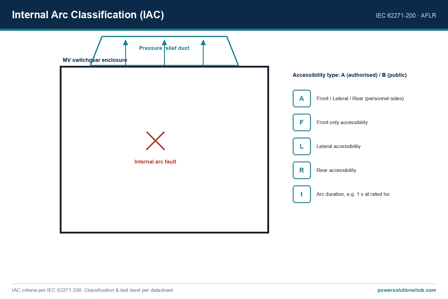
MV Cable Termination Installation Best Practice

MV Cable Termination Installation Best Practice: A Step-by-Step Engineering Guide

A medium voltage (MV) cable termination is the engineered interface that controls electric field stress, restores insulation integrity, and provides a mechanical and environmental seal at the point where a shielded power cable connects to switchgear, a transformer bushing, or an overhead line — and correct installation of it is one of the single biggest factors governing the long-term reliability of an MV network. This guide walks through the physics behind termination design, the key calculations an engineer should perform before specifying hardware, a fully worked sizing example, a practical comparison of termination types, and the installation pitfalls that cause the majority of field failures. It is written for project engineers, panel builders, and maintenance teams working across the Middle East and Gulf region (including Egypt and Saudi Arabia), North Africa, the CIS, and Sub-Saharan Africa, where high ambient temperatures, dust ingress, and long outdoor cable runs make termination quality especially critical.

MV Cable Termination Installation Best Practice — schematic
MV Cable Termination Installation Best Practice — schematic.

Why Termination Design Matters: The Electric Field Problem

Every shielded MV cable has three concentric layers relevant to termination design: the conductor, the extruded insulation, and the metallic or semi-conductive shield. As long as the shield is continuous and grounded, the electric field inside the insulation is radial and well controlled. The problem starts the moment the shield is cut back to expose insulation for connection to a lug or bushing: at that cut point, the field lines crowd and bend, creating a region of highly concentrated electrical stress at the shield cutback edge. Without intervention, this stress concentration leads to partial discharge, treeing, and eventual flashover — often within months rather than years.

Two complementary design responses exist:

  • Stress control — a stress cone (heat-shrink, cold-shrink, or pre-molded) or stress-relief mastic that geometrically and/or capacitively grades the field so it tapers gradually from the shielded region to the bare-insulation region, instead of concentrating at a sharp edge.
  • Creepage extension — insulating skirts or sheds that lengthen the surface path an external flashover would have to travel across the termination body, which becomes especially important outdoors or in dusty/humid/saline environments where surface contamination is likely.

Indoor terminations (inside switchgear cable compartments or dry, clean rooms) typically rely primarily on stress control with modest creepage. Outdoor terminations exposed to pollution, UV, and moisture need significantly more creepage distance and usually a fully skirted or porcelain/composite outdoor termination kit.

Selection reference
Selection reference.

The Method: Field-Grading, Clearance, and Creepage Calculations

Three calculations should be performed (or verified against the termination manufacturer’s kit selection tables) before installation:

1. Shield cutback / stress cone length. The stress cone or stress-relief tube length is sized by the manufacturer per cable insulation level and conductor cross-section; the installer’s job is to cut back the cable shield and insulation to the exact dimensions given in the kit instructions — not “close enough.” Any deviation shortens the engineered grading path and reintroduces a stress hotspot.

2. Minimum phase-to-phase and phase-to-ground clearance. For a given system voltage, clearance requirements scale with the rated withstand voltage of the installation (basic insulation level, BIL). The working principle: the air (or oil, or SF6) gap between phases, and between a phase and an earthed surface, must be sufficient that the peak lightning-impulse withstand voltage of the system does not cause flashover across that gap. This is why three-core cables terminating into a compact cubicle may require separation sleeves or trifurcating boots even when individual phase terminations are correctly stress-controlled.

3. Creepage distance (outdoor/polluted environments). The relevant design parameter is specific creepage distance, expressed in millimetres of surface path per kV of highest system voltage (mm/kV), graded by pollution severity class (light, medium, heavy, very heavy) in line with IEC 60815. A termination selected for a “light pollution” creepage class in a coastal, dusty, or industrial environment is a common root cause of premature flashover failures in export projects — the electrical rating of the cable and kit may be correct, but the surface design is mismatched to the site’s environmental severity.

4. Torque for crimped/bolted connections. Lug crimping must follow the tool-and-die combination specified by the connector manufacturer for the exact conductor size, and bolted bus connections must be torqued to the fastener manufacturer’s specified value — under-torque causes high-resistance hot spots, over-torque can crack cast or compressed terminals.

Worked Example: Verifying Cable and Termination Current Rating Before Installation

Before specifying a termination kit, the engineer must confirm the termination’s continuous current rating is not the limiting link in the circuit. Consider a typical application:

Given: A 1250 kVA, 11 kV distribution transformer feeding a ring main unit via a single-core XLPE cable terminated at both ends.

Step 1 — Calculate transformer rated current:

I = S / (√3 × V)

I = 1,250,000 / (1.732 × 11,000)

I = 1,250,000 / 19,052

I ≈ 65.6 A

Step 2 — Compare against cable and termination rating. The selected cable and its termination kit must each carry at least 65.6 A continuously at the installation’s ambient temperature and laying/derating conditions (grouping, burial depth, ambient temperature correction factors per the cable manufacturer’s data). If, for example, the site ambient and grouping derating factor is 0.9, the required as-installed capacity becomes:

I_required = 65.6 / 0.9 ≈ 72.9 A

Step 3 — Check short-circuit withstand. The termination and lug system must also survive the let-through energy of a fault for the duration the upstream protection takes to clear it. If, for example, the upstream relay is set to clear a fault in 0.5 seconds and the prospective fault current at that point is 20 kA, the thermal withstand requirement for the cable/lug assembly is approximately:

I²t = (20,000)² × 0.5 = 2 × 10⁸ A²s

This value is then checked against the cable conductor’s and the termination lug’s short-time withstand rating (from the manufacturer’s I²t or k² S² tables) to confirm the connection can absorb that energy without conductor damage or lug loosening. This two-step check — continuous current first, short-circuit withstand second — is the core of any termination sizing exercise and should be documented in the project’s cable schedule before procurement.

Termination Type Comparison

Termination Type Typical Environment Field-Grading Method Relative Installation Skill Required Typical Application
Heat-shrink termination Indoor, dry switchgear compartment Stress-relief mastic + heat-shrink stress tube Moderate (torch technique, timing) Ring main unit, indoor switchgear cable box
Cold-shrink termination Indoor or mildly outdoor Pre-stretched elastomeric stress cone, no open flame Low–moderate (core removal, cleanliness) Confined spaces, hazardous areas, retrofits
Push-on / slip-on pre-molded termination Indoor, compact cubicles Pre-molded capacitive/geometric stress cone Low (consistent factory geometry) Switchgear, RMUs, transformer boxes
Outdoor skirted termination (porcelain/composite) Outdoor, polluted/coastal/desert Stress cone + extended creepage sheds High (skirts, sealing, weatherproofing) Overhead line risers, outdoor transformer connections

Selection Criteria and Common Pitfalls

Selection criteria: – Match the termination kit’s rated voltage class and conductor size range exactly to the cable being terminated — kits are not universally interchangeable across insulation thickness ranges. – Select indoor vs. outdoor kit type based on the actual installation environment, not just the switchgear type — an RMU installed in an unconditioned, dusty substation may still warrant indoor-rated kits with reinforced creepage. – Verify compatibility between the cable’s shield/screen system (copper tape, wire screen, or concentric neutral) and the kit’s grounding/bonding components. – Confirm available working space and bending radius in the cable compartment before selecting tri-core trifurcating boots versus single-core separated terminations.

Common field pitfalls: – Shield cutback errors — cutting the semi-conductive and metallic shield too short or too long relative to the kit instructions, destroying the engineered stress-grading geometry. – Contamination during assembly — dust, moisture, or skin oils on the exposed insulation surface before the stress cone is applied create latent partial-discharge sites. – Incorrect crimp tool/die — using a die sized for a different conductor cross-section results in a mechanically and electrically weak crimp that overheats under load. – Inadequate phase separation — omitting separation sleeves on tri-core terminations in compact low-clearance compartments, increasing phase-to-phase flashover risk. – Skipping the heat-shrink dwell time — moving to the next step before the shrink material has fully recovered and bonded compromises both sealing and stress control. – No post-installation test — commissioning the circuit without a cable/termination insulation or partial-discharge test leaves undetected assembly defects to fail in service, usually under full load or fault conditions.

Correct termination practice also depends on compatible upstream and downstream equipment — properly rated MV switchgear with adequately sized cable compartments, and [protection relays](/what-is-a-medium-voltage-protection-relay-mv-protection-relay/) set to clear faults within the termination’s short-time withstand window, both reduce stress on the termination point. Where the circuit feeds a distribution transformer, the transformer-side termination deserves equal attention since bushing-side terminations are just as failure-prone as switchgear-side ones.

Standards

Medium voltage cable accessory design and testing is governed by the IEC 60502 series (power cables with extruded insulation and their accessories for rated voltages from 1 kV up to 30 kV) for the cable and termination/joint construction, while outdoor insulator creepage and pollution performance is addressed under IEC 60815 (selection of insulators in respect of polluted conditions). Site acceptance testing of installed cable systems typically follows IEC 60502-2/-4 guidance for after-laying tests. Engineers should always cross-check the specific termination kit’s type-test certificate against the cable’s actual insulation construction and the project’s environmental pollution class before installation.

Related guides

See also our guides on medium voltage switchgear, gas-insulated switchgear and metal-clad switchgear.

What is a medium voltage cable termination?

A medium voltage cable termination is an engineered accessory fitted to the end of a shielded MV power cable to control electric field stress at the shield cutback point and to provide an insulated, environmentally sealed connection to switchgear, transformer bushings, or overhead lines.

Why does cutting the cable shield create a problem?

Cutting the shield interrupts the uniform radial electric field inside the cable insulation, concentrating electrical stress at the cutback edge; without a stress cone or equivalent field-grading component, this concentration causes partial discharge and eventual insulation failure.

What is the difference between heat-shrink and cold-shrink terminations?

Heat-shrink terminations use a torch to recover a heat-shrinkable stress tube and sealing components onto the cable, while cold-shrink terminations use a pre-stretched elastomeric tube that is mechanically removed from a support core to shrink onto the cable without open flame — making cold-shrink preferable in hazardous or confined areas.

How is creepage distance determined for outdoor terminations?

Creepage distance is specified in millimetres per kV of system voltage and graded by site pollution severity (light to very heavy) per IEC 60815; coastal, desert-dust, and industrial sites require a higher creepage class than clean indoor environments.

Does the termination need to be tested after installation?

Yes — an after-laying or commissioning test (insulation resistance, DC/VLF withstand, or partial-discharge test per IEC 60502 guidance) should be performed before energizing the circuit to catch assembly defects such as contamination or incorrect shield cutback.

Can a single termination kit cover multiple conductor sizes?

Most kits are rated for a defined conductor cross-section and insulation-diameter range; using a kit outside its specified range compromises the stress-cone geometry and creepage design, so the kit must always be matched to the exact cable dimensions.

What causes most MV termination failures in the field?

The majority of failures trace back to installation workmanship issues — incorrect shield cutback length, surface contamination before stress-cone application, wrong crimp tooling, or insufficient heat-shrink dwell time — rather than a defect in the termination kit itself.

Looking for medium voltage cable terminations?

Looking for high-quality medium voltage cable terminations? We provide expert engineering support and reliable products for all your medium voltage needs.

For quotations and requests: info@electricistanbul.com

WhatsApp: +90 501 076 69 91

Cable Jointing and Termination Faults

Cable Jointing and Termination Faults: Causes, Formulas & Standards

Cable jointing and termination faults are electrical failures that originate at the accessory point where a medium-voltage (MV) power cable is joined to another cable section or connected to switchgear, transformers, or overhead lines, and they are most often triggered by localized electric field concentration, partial discharge, moisture ingress, or defective workmanship rather than by the cable insulation itself. Because the cut end of a cable interrupts the uniform coaxial field that exists along its length, accessories are inherently the weakest electrical point in any MV circuit, and understanding the underlying field physics is essential for specifying, installing, and testing joints and terminations correctly. This guide works through the governing formulas, a fully computed example, a comparison of accessory types, and the IEC/IEEE framework that governs design and testing — relevant across every export market we serve, including the Middle East and Gulf (including Egypt and Saudi Arabia), North Africa, the CIS region, and Sub-Saharan Africa, where dust pollution, heat cycling, and humidity each place different demands on accessory selection.

Cable Jointing and Termination Faults — schematic
Cable Jointing and Termination Faults — schematic.

Why Jointing and Termination Faults Matter

Along an intact cable run, the semi-conductive screen keeps the electric field radially symmetric and confined within the insulation. At a joint or termination, that screen is cut and removed over a short length to expose the conductor, which creates a sharp discontinuity: field lines that were previously contained now try to escape along the insulation surface, producing a tangential stress component that did not exist before. If this stress is not controlled, it leads to partial discharge (PD), tracking along the interface, localized overheating at crimped or bolted connections, and — over months or years — a flashover or thermal runaway failure. Because joints and terminations concentrate stress that the rest of the cable does not see, a very large share of MV cable circuit failures reported in field studies trace back to the accessory rather than to the cable body itself, which is why accessory design, installation quality, and post-installation testing deserve engineering attention equal to — or greater than — that given to the cable selection described on our [medium voltage switchgear](/what-is-mv-switchgear-medium-voltage-switchgear/) and distribution transformer hub pages.

Selection reference
Selection reference.

The Method: Electric Field and Stress-Control Formulas

Radial field in coaxial cable insulation

For a single-core cable with conductor radius r_c and insulation outer radius r_i, operating at phase-to-ground voltage U₀, the radial electric field at radius r follows the classical coaxial-capacitor formula:

E(r) = U₀ / [r × ln(r_i / r_c)]

The field is highest at the conductor surface (r = r_c) and falls off logarithmically toward the outer screen. This formula is the starting point for sizing insulation thickness and for predicting where stress will concentrate once the screen is cut back at a joint or termination.

Stress-cone / stress-control design

At a termination, the cut edge of the semi-conductive screen behaves like a sharp metallic edge sitting in a dielectric, which drives local field enhancement far beyond the bulk value given by the formula above. Two engineering methods bring this back under control:

  • Geometric (capacitive) stress control — a cone-shaped insulating body that gradually increases the effective insulation thickness at the screen cut-back point, spreading the field over a longer path (the classical “stress cone”).
  • Refractive (resistive/capacitive) stress control — a tube or mastic with a non-linear or high-permittivity material that electrically “smooths” the discontinuity without a large physical cone, commonly used in heat-shrink and cold-shrink kits.

Short-circuit thermal withstand at the joint

A joint or termination must also survive the fault current that could pass through it before protection operates. The standard thermal short-circuit formula for conductors (the basis of IEC 60949) is:

S = I × √t / k

where S is the minimum conductor cross-section (mm²), I is the fault current (A), t is the fault clearance time (s), and k is a material constant (for copper conductors, k is commonly taken around 143 for XLPE-insulated cable under adiabatic short-circuit conditions). This same relationship is used to check that the jointing sleeve, compression lug, and connecting ferrule are not the limiting link in the fault-current path.

Worked Example: Stress, Creepage, and Fault Withstand at an 11 kV Termination

Step 1 — Maximum electric stress at the conductor. Take an 11 kV cable (U₀ ≈ 6.35 kV phase-to-ground), with an illustrative conductor radius r_c = 10 mm and insulation outer radius r_i = 20 mm.

E_max = U₀ / [r_c × ln(r_i / r_c)] = 6,350 / [0.01 × ln(2)] = 6,350 / (0.01 × 0.693) ≈ 916,300 V/m ≈ 0.92 kV/mm

This is the design-point stress the stress cone or heat-shrink stress tube at the termination must manage without initiating partial discharge.

Step 2 — Creepage distance for the environment. IEC 60815 defines specific creepage distance as a function of pollution severity, expressed in mm per kV of system voltage. For a 12 kV-class termination:

  • Light pollution (class a, ≈16 mm/kV): L = 12 × 16 = 192 mm
  • Heavy pollution — e.g. coastal/desert dust environments common across the GEO region (class d, ≈31 mm/kV): L = 12 × 31 = 372 mm

This nearly doubled creepage requirement is exactly why terminations installed in high-dust or high-salinity sites need longer insulator sheds or silicone outdoor terminations rather than a standard indoor kit — a selection error here is one of the most frequent root causes of flashover faults in the field.

Step 3 — Minimum joint conductor section for a fault. For a prospective fault current I = 20 kA cleared in t = 0.5 s, with copper and k ≈ 143:

S = I × √t / k = 20,000 × √0.5 / 143 = 20,000 × 0.707 / 143 ≈ 98.9 mm²

If the jointing ferrule or compression lug at the accessory has a smaller effective cross-section than this, it — not the cable — becomes the thermal weak point during a through-fault, even if the joint tested fine at rated load current.

Comparison of Common MV Jointing and Termination Methods

Accessory type Stress-control principle Typical strength Typical vulnerability
Heat-shrink termination/joint Refractive stress tube (resistive/capacitive coating) Fast installation, flexible, widely stocked Sensitive to surface prep and shrink temperature control
Cold-shrink termination/joint Pre-expanded elastomeric sleeve, no open flame Safer installation in confined/hazardous areas Requires correct tube removal sequence; sleeve relaxation if oversized
Push-on separable connector (plug-in bushing) Factory-molded geometric stress cone Fully enclosed, very low PD risk when correctly mated Needs matched interface tolerance to switchgear bushing
Resin/epoxy-filled joint Cast resin body embedding factory or field stress control Robust sealing against moisture ingress Longer cure/installation time; sensitive to resin mixing errors
Taped/hand-built joint (legacy, paper-insulated lead-covered cables) Manually built field grading with tapes Can be repaired almost anywhere Highly dependent on installer skill; higher failure incidence

Selection Criteria and Field Pitfalls

Match the accessory to the cable insulation system. A kit designed for XLPE cable will not necessarily grade the field correctly on paper-insulated lead-covered (PILC) cable, and vice versa; always confirm insulation type, not just voltage class.

Size creepage distance to the pollution environment, not just the rated voltage, as shown in the worked example — this is the single most common cause of outdoor termination flashover in hot, dusty, or coastal GEO markets.

Allow for thermal cycling. Conductors and sleeves expand and contract with load cycling; joints must accommodate this movement without loosening torque on connectors or disturbing the stress-control interface.

Control cable screen bonding. Screens must be grounded with a defined bonding method (single-point, both-ends, or cross-bonded) appropriate to circuit length and fault levels; incorrect bonding causes circulating currents, screen overheating, and accelerated insulation aging at the termination.

Use the correct crimping/compression tooling and die set matched to the connector and conductor size; under- or over-compression is a leading cause of hot-spot failures discovered later by thermography.

Commission with electrical testing, not just visual inspection. Very low frequency (VLF) withstand testing, tan-delta/dissipation factor measurement, and partial discharge (PD) testing are the recognized methods for detecting a latent jointing or termination defect before it becomes an in-service failure — complementing protection schemes covered on our [protection relay](/what-is-a-medium-voltage-protection-relay-mv-protection-relay/) hub page, which clear the fault but cannot prevent a weak accessory from failing again.

Governing Standards

MV cable accessory design, materials, and type testing are addressed by IEC 60502 (power cables with extruded insulation, rated voltages up to 30 kV) and IEC 60840 (extruded cables for higher voltage ranges), while IEC 60229 covers tests on cable oversheaths used for jointing/sealing integrity. Thermal short-circuit withstand calculations for cables and accessory conductors follow IEC 60949. Selection of creepage distance for polluted environments follows IEC 60815, and high-voltage withstand/PD test procedures reference IEC 60060. In North American and related export practice, IEEE 48 governs test procedures for AC cable terminations and IEEE/ANSI 404-aligned practice covers cable joints. Always confirm the applicable standard against the specific cable insulation system and voltage class before accepting a jointing or termination design.

Related guides

See also our guides on gas-insulated switchgear, ring main units and metal-clad switchgear.

What is the most common root cause of MV cable jointing faults?

Uncontrolled electric field concentration at the screen cut-back point — usually from incorrect stress-cone positioning, contaminated or poorly prepared cable surfaces, or mismatched kit selection — is the most frequently cited root cause, often confirmed afterward by partial discharge analysis.

How is electric stress at a termination calculated?

Using the coaxial field formula E(r) = U₀ / [r × ln(r_i/r_c)], which gives the radial stress inside the insulation; the actual peak at the screen cut edge is higher and is why dedicated stress-control geometry or material is required.

Why does pollution level change the required creepage distance?

IEC 60815 defines specific creepage distance in mm/kV according to pollution severity class; heavier pollution (dust, salt deposits) requires a longer surface leakage path to avoid flashover, as shown in the worked example above.

Can a joint or termination be the weak point during a fault even if it is fine at normal load?

Yes — the thermal short-circuit formula S = I√t/k shows that connectors and ferrules need their own cross-sectional adequacy check against the prospective fault current and clearance time, independent of their continuous current rating.

What tests detect a latent jointing fault before failure?

VLF withstand testing, tan-delta (dissipation factor) measurement, and partial discharge testing are the standard diagnostic methods for verifying accessory integrity after installation.

Is screen bonding relevant to jointing faults?

Yes — incorrect single-point versus cross-bonding arrangements can induce circulating currents in the screen, causing localized heating precisely at the joint or termination point.

Do heat-shrink and cold-shrink kits perform the same stress-control function?

Both use refractive (resistive/capacitive) stress control rather than a large geometric cone, but they differ in installation method — heat-shrink requires controlled heating while cold-shrink uses a pre-stretched sleeve removed over the cable, which is preferred in hazardous or confined installation areas.

Looking for medium voltage cable terminations?

Looking for high-quality medium voltage cable terminations? We provide expert engineering support and reliable products for all your medium voltage needs.

For quotations and requests: info@electricistanbul.com

WhatsApp: +90 501 076 69 91
MV Cable Termination Selection and Sizing

MV Cable Termination Selection and Sizing: A Step-by-Step Engineering Guide

An MV cable termination is the engineered interface that connects a shielded medium-voltage power cable to switchgear, a transformer bushing, or an overhead line, restoring electrical stress control, insulation integrity, and mechanical sealing at the cable end. Correct termination selection and sizing is a first-principles exercise that combines the system’s rated voltage class, the cable’s conductor cross-section and insulation type, the expected load and short-circuit current, and the installation environment (indoor dry-type cabinet, outdoor pole, or oil-filled transformer compartment). This guide walks through the governing formulas, a fully worked numerical example, a practical comparison table, and the IEC standards that govern termination design, so that specifying engineers across the Middle East and Gulf region including Egypt and Saudi Arabia, North Africa, the CIS states, and Sub-Saharan Africa can standardize their termination selection process for export and EPC projects.

MV Cable Termination Selection and Sizing — schematic
MV Cable Termination Selection and Sizing — schematic.

Why Termination Selection Matters

A cable termination is not a passive accessory — it is the single highest-stress point in an MV cable system. At the cut end of a shielded cable, the uniform radial electric field that exists along the cable body is abruptly interrupted when the semi-conducting screen stops, creating a concentrated stress point unless it is controlled by a stress cone, pre-molded stress-control component, or heat-shrink stress tube. An undersized or incorrectly selected termination can lead to partial discharge, insulation tracking, and eventual flashover — often the root cause of MV cable failures in the field rather than the cable body itself. Selecting the termination therefore means matching three independent parameters simultaneously: the system voltage class, the conductor ampacity, and the mechanical/environmental duty (indoor vs outdoor, oil-immersed vs air-insulated), while also confirming the let-through short-circuit current the termination’s clamp and lug must survive.

For background on the switchgear bays these terminations usually connect into, see our MV switchgear hub and [protection relay](/what-is-a-medium-voltage-protection-relay-mv-protection-relay/) guides; terminations into transformer bushings are covered conceptually in our transformer resources.

Selection reference
Selection reference.

The Method: Formulas Governing Termination Sizing

Termination sizing follows four sequential calculation steps.

Step 1 — Rated current (ampacity check). The rated/load current that the termination’s lug and connector must carry continuously is derived from the system’s apparent power and voltage:

I = S / (√3 × V)

where I is the line current in amps, S is apparent power in kVA, and V is the rated line-to-line voltage in kV. The termination’s compression lug and connector size must be selected for the cable’s conductor cross-section at or above this current, with sufficient thermal margin for the insulation class.

Step 2 — Short-circuit thermal withstand. The cable conductor and termination clamp must survive the fault current for the duration the upstream protection takes to clear it. The adiabatic short-circuit formula for conductor thermal withstand is:

I_sc × √t = k × A

where I_sc is the fault current in kA, t is the fault clearing time in seconds, A is the conductor cross-sectional area in mm², and k is a material constant for the conductor/insulation combination. Rearranged, the maximum allowable fault duration for a given conductor size and fault level is:

t = (k × A / I_sc)²

Step 3 — Dielectric/BIL compatibility. The termination’s rated voltage class and basic insulation level (BIL) must be equal to or greater than the system’s nominal and lightning-impulse withstand requirements. This is a direct one-to-one match against the switchgear or transformer bushing rating — a termination can never be “upgraded” electrically beyond its own insulation design.

Step 4 — Creepage distance for outdoor/polluted environments. For outdoor terminations, the minimum creepage distance (surface leakage path, in mm) is obtained by multiplying the system’s phase-to-phase voltage (in kV) by a pollution-severity factor (mm/kV) selected per the site’s pollution class (light, medium, heavy, or very heavy), as defined in IEC 60815. Coastal, desert-dust, and industrial sites typically require a heavier pollution class and therefore a longer creepage path than a clean indoor cabinet.

Worked Example: Sizing a Termination for an 11 kV Feeder

Consider a 1000 kVA distribution transformer feeder operating at 11 kV, protected by an upstream relay with a fault-clearing time of 0.5 seconds, and a prospective fault level of 20 kA at the termination point. We will size the termination’s current rating, verify thermal withstand, and determine the minimum outdoor creepage distance.

Step 1 — Rated current. I = S / (√3 × V) = 1,000 / (1.732 × 11) ≈ 1,000 / 19.05 ≈ 52.5 A

For example, at this 52.5 A load current, a termination kit rated for the cable’s conductor size (e.g., 50–95 mm² depending on cable selection) with ample thermal margin above 52.5 A would be selected — not a kit sized at the bare minimum, to allow for ambient temperature derating and future load growth.

Step 2 — Short-circuit thermal check. Using the adiabatic formula with an illustrative copper conductor constant k ≈ 143 (A·s^0.5/mm², a commonly cited reference value for XLPE-insulated copper conductors) and a 95 mm² conductor:

Maximum withstand current for t = 0.5 s: I_sc(max) = k × A / √t = (143 × 95) / √0.5 ≈ 13,585 / 0.707 ≈ 19,215 A ≈ 19.2 kA

For example, comparing this to our assumed fault level of 20 kA shows the 95 mm² conductor/termination combination is marginally undersized for a 0.5 s clearing time — the engineer would either upsize the conductor/termination to 120 mm², or confirm the protection relay can clear the fault faster (e.g., at 0.3 s instead of 0.5 s):

I_sc(max) at 0.3 s = (143 × 95) / √0.3 ≈ 13,585 / 0.548 ≈ 24,790 A ≈ 24.8 kA

This second calculation shows that reducing the clearing time to 0.3 s brings the withstand comfortably above the 20 kA fault level, illustrating the direct trade-off between conductor/termination size and protection relay speed — a coordination exercise that should always be cross-checked against your protection relay settings.

Step 3 — Dielectric check. An 11 kV system requires a termination rated for at least the equivalent voltage class with adequate BIL margin for lightning/switching impulses — this is a straightforward nameplate match against the switchgear bay or transformer bushing rating.

Step 4 — Outdoor creepage (if applicable). For an outdoor termination on this 11 kV feeder in a medium pollution zone, the creepage distance is calculated as phase-to-phase voltage (kV) × pollution factor (mm/kV per IEC 60815 pollution class), giving the minimum acceptable surface leakage path in mm for the selected termination kit. The exact mm/kV factor must be taken from the site-specific pollution class table rather than assumed generically.

Selection and Comparison Table

Selection Criterion Key Question Typical Consequence if Ignored
Voltage class / BIL Does termination rating ≥ system nominal + impulse withstand? Flashover under lightning/switching surge
Conductor ampacity Is lug/connector sized ≥ calculated I = S/(√3·V)? Overheating, lug oxidation, hot-spot failure
Short-circuit withstand Does I_sc·√t ≤ k·A hold for the relay clearing time? Conductor/termination burn-back under fault
Indoor vs outdoor type Dry cabinet, open-air pole, or oil-immersed bushing? Moisture ingress, tracking, premature ageing
Cable insulation type XLPE, EPR, or paper-insulated (PILC)? Incompatible stress-control component, PD
Termination technology Heat-shrink, cold-shrink, or pre-molded push-on? Installation defects, inconsistent stress control
Environmental pollution class Light, medium, heavy, or very heavy per IEC 60815? Insufficient creepage, surface flashover
Single-core vs three-core cable Does geometry match stress-cone/cable-gland design? Poor sealing, screen bonding errors

Selection Criteria and Common Pitfalls

Match the termination to the cable insulation system. Stress-control components (pre-molded stress cones, heat-shrink stress tubes, or cold-shrink modules) are engineered specifically for XLPE, EPR, or legacy paper-insulated lead-covered (PILC) cables. Mixing technologies — for instance, fitting an XLPE-rated stress cone onto a PILC cable — compromises the electric field grading and is a frequent cause of premature failure.

Never oversize the ampacity margin away from fault duty. It is tempting to select the largest available termination lug “for safety,” but oversized lugs on undersized conductors create a thermal mismatch at the crimp interface. The lug, connector, and conductor cross-section must be sized as a matched set per the manufacturer’s crimping/compression die chart.

Account for indoor/outdoor and oil-immersed duty separately. A termination destined for a switchgear cable box (dry, indoor, pollution-controlled) has very different creepage and sealing requirements from one terminating into an oil-filled transformer bushing well, or one mounted outdoors on a pole in a dusty, coastal, or desert environment. Confirm the duty type before finalizing the IEC 60815 pollution class assumption.

Re-verify short-circuit coordination whenever protection settings change. The I_sc·√t calculation in Step 2 is only valid for the specific relay clearing time assumed. If protection coordination studies are revised — for example, after adding new downstream feeders — the termination’s short-circuit thermal withstand must be re-checked against the new clearing time.

Confirm screen/earthing continuity. Cable screens must be correctly bonded and earthed at the termination per the system’s earthing philosophy (solid, single-point, or cross-bonded for long circuits), since incorrect screen bonding can introduce circulating currents or leave the screen floating at a hazardous potential.

Standards Governing MV Cable Terminations

MV cable termination design, testing, and type approval are principally governed by the IEC 60502 series (“Power cables with extruded insulation and their accessories for rated voltages from 1 kV up to 30 kV”), which addresses cable and accessory (including termination) construction and test requirements for this voltage range. Outdoor insulator and termination creepage/pollution performance is addressed by IEC 60815 (“Selection and dimensioning of high-voltage insulators for polluted conditions”). Where terminations interface with switchgear cable boxes, the switchgear’s own enclosure and arc-fault classification is governed separately by the IEC 62271 switchgear series, but this applies to the switchgear enclosure itself, not the termination component. Always confirm the specific sub-part and edition applicable to the project’s voltage class and cable construction with the termination manufacturer’s type-test certificates.

Related guides

See also our guides on medium voltage switchgear, gas-insulated switchgear and ring main units.

What is the difference between heat-shrink, cold-shrink, and pre-molded terminations?

Heat-shrink terminations use a flame or heat gun to shrink a stress-control tube onto the prepared cable end; cold-shrink terminations are pre-expanded over a removable core and shrink at ambient temperature once the core is withdrawn, requiring no open flame; pre-molded (push-on) terminations are factory-manufactured silicone or EPDM components slid directly onto the prepared cable. Each technology has different installation skill requirements and is suited to different site conditions (e.g., cold-shrink for hazardous-area or confined installations where open flame is restricted).

How do I know if I need an indoor or outdoor termination?

The choice depends on where the cable end actually terminates: inside a switchgear cable compartment or dry transformer cable box calls for an indoor-type termination, while a cable rising to an overhead line, pole-mounted transformer, or any exposed outdoor connection requires an outdoor-type termination with appropriate creepage distance and weather sealing per IEC 60815.

Can I use the same termination for single-core and three-core cables?

No. Single-core and three-core cable terminations use different stress-control geometries and gland/sealing designs because the screen bonding, phase separation, and mechanical entry point differ fundamentally between the two cable constructions.

What happens if the termination’s short-circuit withstand is lower than the system’s fault level?

The conductor or termination clamp can overheat and mechanically fail during a through-fault, even if the fault is cleared within the protection relay’s normal operating time, because the adiabatic thermal limit (I_sc·√t ≤ k·A) is exceeded — this is why Step 2 of the sizing method above must always be checked against actual relay coordination settings.

Does termination sizing depend on the switchgear or only on the cable?

Both. The cable determines conductor size, insulation type, and screen construction, while the switchgear or transformer bushing determines the voltage class, BIL, and physical interface (bushing well, cable box clearance) that the termination must match at both ends.

How does pollution class affect termination selection?

In coastal, desert, or industrial sites with airborne salt, dust, or chemical contamination, surface leakage currents across an outdoor termination’s insulating surface increase, requiring a longer creepage distance per the IEC 60815 pollution-severity classification to avoid surface tracking and flashover.

Is a PILC-to-XLPE transition termination different from a standard termination?

Yes. Transition terminations (also called “transition joints” when mid-span) are specifically engineered to manage the different insulation characteristics, screen types, and stress-control requirements between legacy paper-insulated and modern extruded-dielectric cables, and must never be substituted with a standard single-technology termination kit.

Looking for medium voltage cable terminations?

Looking for high-quality medium voltage cable terminations? We provide expert engineering support and reliable products for all your medium voltage needs.

For quotations and requests: info@electricistanbul.com

WhatsApp: +90 501 076 69 91
Transformer Differential Protection and REF

Transformer Differential Protection and REF: Principles, Formulas, and Worked Example

Transformer differential protection (ANSI device 87T) is a unit protection scheme that compares current entering and leaving a power transformer winding-by-winding to instantaneously detect internal faults, while restricted earth fault protection (REF, device 87N/64REF) adds sensitive coverage for earth faults near the neutral point that differential protection alone cannot reliably detect. This guide walks engineers and specifiers through the operating principle, the governing formulas, a fully worked numerical example for a two-winding transformer, CT selection pitfalls, and the standards that govern relay application. It is written for utility, EPC, and industrial engineers specifying protection schemes for medium-voltage transformers across the Middle East and Gulf region (including Egypt and Saudi Arabia), North Africa, the CIS, and Sub-Saharan Africa, where transformer protection is typically paired with medium-voltage switchgear and numerical protection relays at the incoming and outgoing bays.

Transformer Differential Protection and REF — schematic
Transformer Differential Protection and REF — schematic.

Why Differential and REF Protection Matter

A power transformer is one of the most capital-intensive and longest lead-time assets in a substation. An internal winding fault — turn-to-turn, phase-to-phase, or phase-to-earth inside the tank — can escalate within milliseconds into catastrophic core and tank damage, oil fire risk, and extended downtime measured in months rather than days. Overcurrent relays on the incoming feeder are too slow and too insensitive for this class of fault because they must be graded with downstream devices and cannot “see” a low-magnitude internal fault that does not raise line current enough to operate.

Differential protection solves this by comparing currents at every terminal of the protected zone using Kirchhoff’s current law: in healthy operation, the vector sum of currents entering and leaving the transformer (referred to a common base) is zero. Any internal fault breaks that balance and produces a differential current that the relay uses to trip instantaneously, without any time-grading delay. REF protection extends this principle specifically to the transformer neutral-earthing circuit, where it is the most sensitive method available for detecting low-level earth faults close to the star point — faults that produce a very small line current but can still damage the winding.

Selection reference
Selection reference.

The Method and Governing Formulas

Basic differential principle

For a two-winding transformer with primary current I1 and secondary current I2 (both referred to the same base via CT ratios and vector-group compensation), the relay computes:

  • Differential (operating) current: Id = |I1 − I2|
  • Restraint (bias) current: Ir = (I1 + I2) / 2

In a healthy transformer carrying load current, Id should be close to zero (small residual mismatch from CT errors and tap-changer position). The relay trips when Id exceeds a bias-dependent threshold defined by a dual-slope characteristic: a sensitive pickup near no-load, and a progressively higher percentage slope at higher restraint currents to tolerate CT saturation and on-load tap-changer (OLTC) mismatch during external faults and heavy through-load.

CT ratio and vector-group matching

Before any differential calculation, the relay (or in older schemes, interposing CTs) must correct for two sources of mismatch:

  1. Turns ratio mismatch — the transformer’s primary and secondary rated currents differ because of the voltage transformation ratio, so CT ratios on each side must be chosen so that secondary currents are nominally balanced at rated load.
  2. Vector-group phase shift — a Dyn11 or similar transformer introduces a 30° (or multiple of 30°) phase shift between primary and secondary currents. Modern numerical relays perform this compensation digitally; older electromechanical and static schemes required physically wired interposing CTs in delta/star configuration.

Rated current formula

The starting point for any CT and setting calculation is the transformer’s rated current on each winding:

I = S / (√3 × V)

where S is the rated apparent power (VA) and V is the rated line voltage (V) of that winding.

Worked Example: 10 MVA, 33/11 kV Transformer

Consider a 10 MVA transformer with an HV winding rated at 33 kV and an LV winding rated at 11 kV, connected Dyn11.

Step 1 — Rated currents on each side

HV side: I(HV) = 10,000,000 / (1.732 × 33,000) ≈ 174.9 A

LV side: I(LV) = 10,000,000 / (1.732 × 11,000) ≈ 524.9 A

Step 2 — CT ratio selection

CTs are normally selected with a primary rating somewhat above the transformer’s rated current, using standard ratios available from the manufacturer’s range. For this example, assume:

  • HV-side CT ratio: 200/1 A
  • LV-side CT ratio: 600/1 A

Step 3 — Secondary (relay input) currents at rated load

HV side: 174.9 / 200 ≈ 0.875 A LV side: 524.9 / 600 ≈ 0.875 A

Because the two CT ratios were chosen deliberately to balance the secondary currents, the relay sees almost equal magnitudes from both sides at rated load — exactly what is needed before the vector-group and phase-shift compensation is applied digitally inside the relay.

Step 4 — Differential and restraint current at full load (healthy condition)

Id = |0.875 − 0.875| = 0 A (ignoring small CT accuracy-class errors) Ir = (0.875 + 0.875) / 2 = 0.875 A

Step 5 — Illustrative pickup and slope setting

A typical numerical relay bias characteristic (illustrative, for teaching the concept — actual settings are project-specific and configured per relay manufacturer instructions) might use:

  • Minimum pickup: a small fraction of rated secondary current, e.g. around 0.2–0.3 A in this example, to ride through normal CT mismatch and magnetising inrush
  • First slope: a modest percentage of restraint current up to roughly twice rated current, to tolerate OLTC mismatch
  • Second, steeper slope above that point, to remain stable during heavy through-faults where CT saturation is more likely

Step 6 — Internal fault scenario

Suppose an internal fault causes the HV side to feed 150 A (primary) into the fault while the LV side, if the fault is close to the HV terminals, contributes very little or current flows the “wrong” way. Referred through the CT ratio, this produces a large Id relative to Ir, far above the bias threshold, and the relay trips instantaneously — demonstrating the core value of unit protection versus time-graded overcurrent protection.

Restricted Earth Fault (REF) Worked Concept

REF protection compares the current measured by a CT in the transformer neutral-to-earth connection with the vectorial sum of the three phase CTs on the same winding. In healthy operation and even during external earth faults, these two quantities should balance (an external fault current flows through the phase CTs and the neutral CT equally and cancels in the REF comparison). An internal earth fault on that winding — even one too small for ordinary overcurrent or line differential protection to detect — unbalances this comparison and the REF element operates.

A key design rule: the neutral CT and the three phase CTs used for REF must have matching ratios and similar magnetising characteristics, otherwise spurious differential current appears during heavy through-faults and either causes false trips or forces the setting to be desensitised, defeating the purpose of REF’s high sensitivity. This is why REF is usually specified as a dedicated, separately wired scheme rather than being derived mathematically inside the main 87T differential algorithm.

Selection and Comparison Table

Aspect Overall (87T) Differential Restricted Earth Fault (87N/64REF)
Fault types detected Phase-phase, phase-earth, turn-to-turn (large) Earth faults near winding/neutral, including low-magnitude
Sensitivity to earth faults Moderate (depends on fault location) High — most sensitive earth-fault protection available
CT requirement CTs at each transformer terminal, ratio-matched per side Matched-ratio CTs: neutral CT + sum of phase CTs on one winding
Vector-group compensation Required (digital or interposing CT) Not required — scheme is inherently per-winding
Typical speed Instantaneous (no grading delay) Instantaneous (no grading delay)
Stability concern CT saturation on heavy through-faults; OLTC mismatch CT ratio/characteristic mismatch between neutral and phase CTs
Common relay standard reference IEEE C37.91 guidance; IEC 60255 relay performance IEEE C37.91 guidance; IEC 60255 relay performance

Selection Criteria and Common Pitfalls

  • CT accuracy class and knee-point voltage: differential and REF schemes demand CTs with adequate knee-point voltage to avoid saturation during close-in through-faults; undersized CTs are a leading cause of nuisance tripping.
  • Vector group and phase compensation: always confirm the relay’s vector-group compensation setting matches the actual transformer connection (e.g., Dyn11) — a mismatch produces a permanent spurious differential current that masks genuine faults or causes standing trips.
  • Tap-changer range: the differential bias slope must accommodate the full OLTC tap range, since the apparent mismatch between HV and LV currents changes as the transformer moves off its nominal tap.
  • Inrush restraint: transformer energisation produces a large magnetising inrush current rich in second-harmonic content; the relay’s inrush (harmonic restraint or blocking) function must be correctly enabled and set to avoid false trips on energisation.
  • REF CT matching: as noted above, neutral and phase CTs feeding the REF element must be ratio- and characteristic-matched; mixing CT types or ratios is a frequent field error.
  • Coordination with switchgear and other protection layers: differential and REF trip the associated circuit breakers in the switchgear on both sides of the transformer; protection engineers should review this alongside the switchgear protection and control philosophy when selecting protection relays.

Standards and References

Application of transformer differential and restricted earth fault protection is most commonly guided by IEEE C37.91 (Guide for Protective Relay Applications to Power Transformers), which addresses CT selection, bias settings, inrush restraint, and REF scheme design in detail. The performance characteristics of the numerical protection relays implementing these functions are governed by IEC 60255 (measuring relays and protection equipment). The transformer itself, including its vector group, rated power, and insulation levels used as inputs to these calculations, is specified per IEC 60076 (power transformers). Where the relay communicates via a substation automation network, IEC 61850 governs the data modelling and communication interface. Project-specific settings should always be finalised using the actual transformer nameplate data, CT test certificates, and the selected relay manufacturer’s setting guide.

Related guides

See also our guides on gas-insulated switchgear, ring main units and metal-clad switchgear.

What is the difference between transformer differential protection and restricted earth fault protection?

Differential protection (87T) compares currents at all transformer terminals to detect most internal fault types, while REF (87N/64REF) is a dedicated, more sensitive scheme focused specifically on earth faults near one winding’s neutral point, which ordinary differential protection may not detect reliably at low fault currents.

Why do transformer differential relays need harmonic (inrush) restraint?

Energising a transformer produces a magnetising inrush current that looks like a large differential current to the relay but is not a fault. Harmonic restraint, typically based on second-harmonic content, allows the relay to distinguish inrush from genuine internal faults and avoid a false trip.

Why must CT ratios be matched on each side of the transformer for differential protection?

Because the primary and secondary rated currents of a transformer differ according to the voltage ratio, CT ratios must be chosen so that the secondary currents fed to the relay are close to balanced at rated load; otherwise the relay sees a permanent false differential current.

Does vector group affect differential protection settings?

Yes. A transformer vector group such as Dyn11 introduces a phase shift between HV and LV currents that must be compensated, either digitally inside a numerical relay or historically via interposing CTs, before the differential comparison is valid.

Can restricted earth fault protection detect faults that differential protection misses?

Yes — REF is specifically designed to be more sensitive to low-magnitude earth faults near the transformer neutral than the overall differential scheme, making the two protections complementary rather than redundant.

What standard governs the application of transformer differential and REF protection?

IEEE C37.91 is the primary application guide for protective relaying of power transformers, while the relay hardware performance follows IEC 60255 and the transformer itself is specified per IEC 60076.

Where should differential and REF relays be applied relative to the switchgear?

The current transformers and trip outputs for 87T and REF schemes are coordinated with the circuit breakers in the medium-voltage switchgear on each side of the transformer, so protection relay settings should be reviewed together with the overall switchgear protection and control architecture.

Looking for medium voltage transformers?

Looking for high-quality medium voltage transformers? We provide expert engineering support and reliable products for all your medium voltage needs.

For quotations and requests: info@electricistanbul.com

WhatsApp: +90 501 076 69 91

IEC 61439 Explained

IEC 61439 Explained: Low-Voltage Assembly Ratings, Verification & Design Guide

IEC 61439 is the international standard series that defines the design, ratings, construction, and verification requirements for low-voltage switchgear and controlgear assemblies (LVSCA) — the panels, switchboards, motor control centres, and distribution boards installed between transformers, generators, and downstream loads. This guide walks through how the standard’s core ratings are calculated, how the mandatory design verifications are performed, and how a buyer or design engineer can apply first-principles formulas to check that a quoted assembly is fit for its intended duty. It is written for procurement and technical teams sourcing low-voltage switchgear across the Middle East and Gulf (including Egypt and Saudi Arabia), North Africa, CIS, and Sub-Saharan Africa, where feeder ratings, fault levels, and ambient temperatures vary widely from project to project.

IEC 61439 replaced the older IEC 60439 series and split responsibility between the original manufacturer (who designs and verifies the assembly system) and the assembly manufacturer (who builds a specific panel using that verified system). Understanding the underlying calculations — not just the certificate — is what lets a buyer compare two seemingly similar panels and know which one actually fits the application.

IEC 61439 Explained — schematic
IEC 61439 Explained — schematic.

The Core Ratings and Formulas Behind IEC 61439

Every IEC 61439 assembly carries a nameplate with ratings that are not arbitrary — each is derived from a calculation tied to the installation’s electrical duty.

1. Rated current (In) The rated current of an incoming functional unit is normally sized from the upstream transformer or generator capacity:

I (A) = S / (√3 × V)

where S is the apparent power in kVA and V is the line-to-line voltage in kV.

2. Rated short-time withstand current (Icw) and peak withstand current (Ipk) These describe the assembly’s ability to survive a fault for a defined duration without mechanical or thermal damage. Icw is normally verified for 1 second unless otherwise agreed, and Ipk (the first peak of the fault current) is derived from Icw using a asymmetry factor, commonly expressed as:

Ipk ≈ n × Icw

where n is a multiplying factor that accounts for the X/R ratio of the system (IEC 60909 gives guidance on typical factors for LV networks).

3. Rated diversity factor (RDF) Because not every outgoing circuit in a switchboard operates at full rated current simultaneously, IEC 61439 allows the assembly manufacturer to declare a diversity factor applied to the sum of individual circuit ratings, reducing the required busbar cross-section compared with a “100% coincident” design.

4. Temperature-rise verification IEC 61439-1 requires that the temperature rise of busbars, connections, and enclosure surfaces stay within defined limits above the ambient reference temperature when carrying rated current continuously. This can be verified either by physical test, by calculation, or — for smaller assemblies — by comparison with a pre-tested reference design within defined size limits.

Selection reference
Selection reference.

Worked Example: Sizing and Verifying an LV Switchboard Feeder

Consider a distribution board fed from a 1000 kVA transformer at a secondary voltage of 0.4 kV, protecting a facility in a region with a relatively high fault level.

Step 1 — Rated current of the incomer

I = S / (√3 × V) = 1000 / (1.732 × 0.4) ≈ 1,443 A

So the incoming busbar and main circuit breaker must be rated at least 1,600 A (the next standard frame size above the calculated 1,443 A) to allow margin for future load growth.

Step 2 — Prospective short-circuit current

Assume the transformer has a short-circuit impedance of 6%. The prospective fault current at the transformer terminals is approximately:

Isc = In / Zpu = 1,443 / 0.06 ≈ 24,050 A ≈ 24 kA

Step 3 — Selecting Icw and Ipk

The assembly’s rated short-time withstand current (Icw) must therefore be specified at not less than 24 kA for 1 second. Using an illustrative peak factor of n ≈ 2.1 for a typical LV X/R ratio:

Ipk ≈ 2.1 × 24 kA ≈ 50.4 kA

This means the busbar bracing, bolted joints, and enclosure structure must be verified (by test or calculation under IEC 61439-1 Annex) to withstand a first-peak let-through force corresponding to roughly 50 kA — a figure the buyer should cross-check against the manufacturer’s type-test report before accepting the design.

Step 4 — Thermal check (I²t concept)

For a fault cleared in 0.5 s by the upstream protection device, the let-through energy is approximately:

I²t = Isc² × t = (24,000)² × 0.5 ≈ 2.88 × 10⁸ A²s

This value is compared against the busbar and cable thermal withstand capability declared by the assembly manufacturer to confirm no conductor damage occurs during the protection device’s clearing time. This step links directly into coordination studies carried out with the protection relays specified on the upstream MV switchgear — see our protection relay guide for how relay time-current curves are selected to keep this energy within safe limits.

The Eight Design Verifications of IEC 61439-1

IEC 61439-1 requires every assembly design to be verified against a defined list of criteria, each of which can be satisfied by testing, calculation, or design rules (comparison with an already-verified reference design).

Verification item Typical verification method Why it matters for the buyer
Strength of materials and parts (corrosion resistance) Test or design rule Ensures enclosure survives installation environment (coastal, desert, humid)
Degree of protection (IP code) Test Confirms ingress protection matches the installation environment
Clearances and creepage distances Measurement/calculation Prevents flashover and tracking at rated voltage
Protection against electric shock and integrity of protective circuits Test/calculation Confirms continuity and earthing effectiveness
Incorporation of switching devices and components Design rule Confirms components are used within their own ratings
Internal electrical circuits and connections Design rule/test Confirms wiring and busbar joints are adequately rated
Terminals for external conductors Design rule Ensures cable lugs/terminals match conductor sizes
Dielectric properties (impulse withstand, power-frequency withstand) Test Confirms insulation margin against overvoltages
Temperature rise Test/calculation Confirms no overheating at rated continuous current
Short-circuit withstand strength Test/calculation Confirms survival of the fault current calculated above
Electromagnetic compatibility (EMC) Test/design rule Confirms correct operation near sensitive electronics
Mechanical operation Test Confirms durability of mechanical interlocks and operating mechanisms

A design that has passed all applicable verifications is described as an IEC 61439-compliant verified assembly, and the assembly manufacturer must be able to produce the supporting test reports or calculation records on request — this is the single most important document a buyer should ask for before accepting delivery.

Selection Criteria and Common Pitfalls

When specifying or evaluating an IEC 61439 assembly, engineers should check the following:

  • Match Icw to the actual fault level at the point of installation, not a generic catalogue value — an undersized withstand rating is the most common design error found during audits.
  • Confirm the rated diversity factor (RDF) used by the manufacturer matches the actual expected loading profile; an optimistic RDF can understate the required busbar size.
  • Verify Form of separation (internal separation between functional units, e.g. busbars vs functional compartments) matches the operational and maintenance philosophy — higher separation forms allow safer live working on adjacent compartments but increase cost and footprint.
  • Check ambient temperature and altitude correction factors applied to the temperature-rise verification, especially for installations in high-ambient Gulf or Sub-Saharan sites.
  • Request the type-test or calculation report referenced in the technical file, not just a compliance statement on the nameplate.
  • Coordinate upstream and downstream protection so that the let-through energy during a fault never exceeds the assembly’s verified short-circuit withstand — this ties the LV switchboard design directly to the settings on the MV switchgear and protection relays feeding it, and to the transformer impedance used in the fault calculation above.

Standards Reference

The governing standard for low-voltage switchgear and controlgear assemblies is IEC 61439-1 (general rules) together with the relevant product-family part, most commonly IEC 61439-2 for power switchgear and controlgear assemblies. Fault-current calculation methods referenced for Icw and Ipk sizing are commonly based on IEC 60909. These standards together define the full lifecycle from rated current determination through to type verification and routine testing at the factory.

Related guides

See also our guides on gas-insulated switchgear, ring main units and metal-clad switchgear.

What is the difference between IEC 61439 and the older IEC 60439?

IEC 61439 replaced IEC 60439 and introduced a clearer split between the “original manufacturer” responsible for the base design and verifications, and the “assembly manufacturer” who builds a specific panel from that verified system, along with a more structured set of design verifications.

How is the rated short-time withstand current (Icw) determined?

Icw is set at or above the prospective short-circuit current calculated at the point of installation (typically derived from the upstream transformer impedance, as shown in the worked example above), and is normally verified for a stated duration such as 1 second.

What does “Form of separation” mean in an IEC 61439 assembly?

Form of separation describes the degree of internal partitioning between busbars, functional units, and terminals, ranging from no separation to full separation of each functional unit including its terminals, and it directly affects safe maintenance access and fault containment.

Can temperature-rise verification be done without a physical test?

Yes — IEC 61439-1 permits verification by calculation or by comparison with an already type-tested reference design, provided the new design stays within the defined limits of the verified reference (dimensions, current rating, ventilation, etc.).

Why does the rated diversity factor matter to a buyer?

The RDF determines how much of the sum of individual circuit ratings the main busbar must actually carry simultaneously; an incorrectly optimistic RDF can lead to undersized busbars that overheat under real operating conditions.

Does IEC 61439 apply to [medium-voltage switchgear](/what-is-mv-switchgear-medium-voltage-switchgear/) as well?

No — IEC 61439 covers low-voltage assemblies (typically up to 1000 V AC); medium-voltage switchgear and controlgear is covered separately under the IEC 62271 series.

What documentation should I request to confirm IEC 61439 compliance?

Ask for the verification report covering the applicable items in the table above (temperature rise, short-circuit withstand, dielectric tests, IP rating), plus the routine test certificate issued for the specific assembly delivered.

Looking for low voltage switchgear?

Looking for high-quality low voltage switchgear? We provide expert engineering support and reliable products for all your medium voltage needs.

For quotations and requests: info@electricistanbul.com

WhatsApp: +90 501 076 69 91
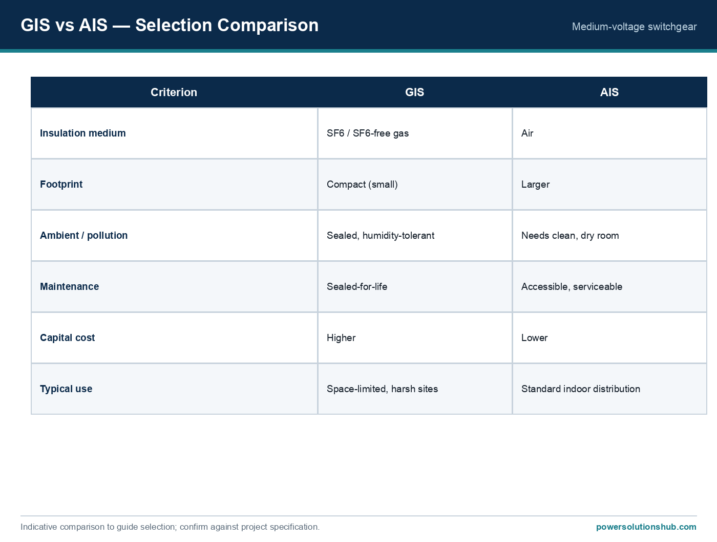
LV Switchboard Faults and Maintenance

LV Switchboard Faults and Maintenance: A First-Principles Engineering Guide

An LV switchboard is a low-voltage power distribution assembly — typically rated up to 1000 V AC — that houses busbars, circuit breakers, fuses, and protection/metering devices used to distribute electrical energy safely from a transformer or generator to downstream loads. LV switchboard maintenance is the structured, standards-based program of inspection, testing, and corrective action that keeps that assembly within its designed thermal, dielectric, and mechanical limits throughout its service life. This guide walks through how faults originate, the first-principles formulas engineers use to quantify risk, a fully worked numerical example, a practical comparison table of fault types, and the governing IEC framework. It is written for utility, industrial, and EPC engineers working across the Middle East and Gulf region (including Egypt and Saudi Arabia), North Africa, the CIS states, and Sub-Saharan Africa, where high ambient temperatures, dust ingress, and variable grid quality accelerate many of the failure modes described below.

LV Switchboard Faults and Maintenance — schematic
LV Switchboard Faults and Maintenance — schematic.

Why LV Switchboard Faults Matter

Unlike medium-voltage switchgear, LV switchboards are often located close to operators, inside plant rooms, or embedded in production lines — so a fault here has a direct and immediate safety consequence, not just a reliability one. The dominant failure mechanisms are:

  • Thermal failure — loose or corroded connections increase contact resistance, raising local temperature until insulation degrades or the joint arcs.
  • Insulation breakdown — moisture ingress, dust tracking, or aged insulation lowers the insulation resistance below a safe threshold, eventually causing a phase-to-earth or phase-to-phase fault.
  • Mechanical fatigue — vibration loosens busbar bolts and terminal lugs over years of thermal cycling.
  • Overload/short-circuit stress — repeated fault-current let-through without proper coordination damages breaker contacts and busbar supports.
  • Arc flash events — the most severe outcome, where a fault escalates into a sustained internal arc, releasing thermal energy that can be catastrophic to nearby personnel.

Because these failure modes are progressive, most of them are detectable — and preventable — with the right calculation-based inspection program, rather than reactive repair after a trip or burn-out.

Selection reference
Selection reference.

The Method: Core Diagnostic Formulas

Three calculations form the backbone of LV switchboard fault analysis and maintenance planning.

1. Rated/load current (baseline for thermal assessment)

For a three-phase system:

I = S / (√3 × V)

where S is apparent power (kVA) and V is line voltage (kV or V). This is the reference current against which thermal imaging and loading studies are compared.

2. Prospective short-circuit current at the switchboard

Isc = V / (√3 × Ztotal)

where Ztotal is the total impedance (transformer + cable + busbar) referred to the LV side, in ohms. This value determines the required breaking capacity of the incoming breaker and the mechanical withstand of the busbar.

3. Joint heating from contact resistance (I²R loss)

P = I² × R

A joint with elevated resistance R dissipates power as heat; sustained operation above the conductor’s thermal class accelerates insulation aging approximately in line with the Arrhenius relationship — every rise of about 8–10 °C above rated operating temperature can roughly halve insulation life, which is why thermographic surveys are a cornerstone of preventive maintenance.

Worked Example: From Transformer Rating to Fault Risk

Consider a 1000 kVA, 11 kV/0.4 kV distribution transformer feeding an LV switchboard.

Step 1 — Rated LV current

I = S / (√3 × V) = 1,000,000 / (1.732 × 400) ≈ 1,443 A

This is the current the LV switchboard’s incoming breaker and busbar must carry continuously under full load.

Step 2 — Transformer impedance voltage

Assume the transformer has a typical impedance voltage of 6% (a common nameplate value for this class of transformer). The transformer’s LV-side impedance is:

Zt = (Uz% / 100) × (V² / S) = 0.06 × (400² / 1,000,000) = 0.06 × 0.16 = 0.0096 Ω

Step 3 — Prospective short-circuit current

Isc = V / (√3 × Zt) = 400 / (1.732 × 0.0096) ≈ 24,040 A ≈ 24 kA

This illustrative figure (ignoring upstream and cable impedance, which would reduce it slightly) tells the engineer that the LV switchboard’s main breaker and busbar bracing must be selected with a short-circuit withstand comfortably above this prospective value, with margin for decrement and asymmetry.

Step 4 — Heating from a degraded joint

Suppose thermal imaging on a busbar joint carrying the full 1,443 A load shows a calculated contact resistance of 0.00005 Ω (50 µΩ) due to surface oxidation, versus a healthy joint resistance of 0.00001 Ω (10 µΩ).

  • Healthy joint: P = I² × R = 1,443² × 0.00001 ≈ 20.8 W
  • Degraded joint: P = 1,443² × 0.00005 ≈ 104 W

A five-fold increase in dissipated power at the same load current is exactly the signature that infrared thermography is designed to catch before the joint reaches a damaging temperature — long before an overcurrent relay would ever see an abnormal reading, because the load current itself hasn’t changed.

This sequence — rated current → fault current → joint heating — is the logical backbone of any LV switchboard condition assessment and should sit alongside protection coordination studies referenced on our [protection relay](/what-is-a-medium-voltage-protection-relay-mv-protection-relay/) and switchgear resource pages.

Fault Types, Detection Methods, and Typical Actions

Fault type Root cause Detection method Typical corrective action
Loose/high-resistance joint Vibration, improper torque, oxidation Infrared thermography, contact resistance (micro-ohmmeter) test Clean, re-torque to specified value, re-test
Insulation degradation Moisture, dust, aging, tracking Insulation resistance (megohmmeter) test, partial discharge survey Clean/dry compartment, replace insulation, improve sealing
Busbar mechanical fatigue Thermal cycling, vibration, inadequate bracing Visual/mechanical inspection, torque check Re-brace, replace fasteners, verify short-circuit withstand design
Overload tripping Load growth beyond design current Load current logging vs. rated I Load redistribution, upsize feeder/breaker
Internal arc fault Combination of the above + ingress of conductive debris Arc-fault detection relays, post-event inspection Isolate, replace damaged sections, review internal arc classification (IAC) design
Corrosion of enclosure/contacts Humidity, coastal/desert dust environments Visual inspection, IP rating verification Improve ventilation/filtration, corrosion-resistant plating

Selection Criteria & Common Pitfalls in Maintenance Programs

  • Set maintenance intervals by risk, not calendar alone. Switchboards in harsh ambient conditions (high dust, humidity, or heavy load cycling common across Gulf and African sites) warrant shorter thermographic and torque-check intervals than clean, climate-controlled plant rooms.
  • Always de-energize and lock out before mechanical torque checks — thermography can be done live, but tightening bolts cannot.
  • Don’t rely on overcurrent protection to catch joint heating. As the worked example shows, a degraded joint can dissipate several times more heat at the same load current, which a thermal-overload relay will not detect until much later.
  • Track trends, not single readings. A single insulation resistance test is a snapshot; recording values over successive outages reveals the rate of degradation and lets you forecast remaining service life.
  • Verify short-circuit withstand after any load growth. If downstream load increases, re-run the Isc calculation — a switchboard sized correctly at commissioning may be under-protected years later if upstream transformer capacity was upgraded.
  • Coordinate arc-flash risk assessments with protection settings. Reducing fault clearing time through better relay coordination is often the most cost-effective way to lower incident energy exposure.
  • Don’t ignore ambient derating. High ambient temperature reduces the effective current-carrying capacity of busbars and cables feeding the switchboard, which should be reflected in the baseline rated-current assumption used for thermography pass/fail limits.

Governing Standards

LV switchboard design and verification is governed primarily by the IEC 61439 series (“Low-voltage switchgear and controlgear assemblies”), which defines design verification, including temperature-rise and short-circuit withstand verification, for the assembly as a whole. Ongoing inspection and periodic testing of the installation fall under IEC 60364-6 (verification of electrical installations), while individual low-voltage switching and protective devices within the board are covered by IEC 60947. Where internal arc performance is a design consideration, the assembly’s internal arc classification should be evaluated against the relevant clauses of IEC 61439. Personnel safety during live diagnostic work (such as thermography) should follow site electrical safety procedures aligned with these IEC assembly and installation standards.

Related guides

See also our guides on gas-insulated switchgear, ring main units and metal-clad switchgear.

How often should an LV switchboard be inspected?

Inspection frequency should be based on criticality, ambient severity, and load profile rather than a fixed calendar rule — critical boards in harsh or dusty environments typically need more frequent thermographic and mechanical checks than lightly loaded boards in clean indoor plant rooms.

What is the single most useful diagnostic tool for LV switchboard maintenance?

Infrared thermography is widely regarded as the most cost-effective tool because it detects joint and contact degradation (via the I²R heating mechanism) long before it would trip a protection device or cause a visible fault.

How is the prospective short-circuit current at an LV switchboard calculated?

It is derived from the supply voltage divided by the total impedance from source to the board (Isc = V / (√3 × Ztotal)), as shown in the worked example above, and is used to verify that breakers and busbars have adequate short-circuit withstand.

Does increasing downstream load always require re-checking the switchboard?

Yes — any increase in connected load changes the rated current baseline used for thermal assessments and may also change upstream transformer or generator sizing, which directly affects the prospective short-circuit current the switchboard must withstand.

What causes most arc flash incidents in LV switchboards?

Most originate from a progressive fault — a loose connection, insulation failure, or contamination ingress — that escalates under load or during a switching operation, rather than from a single catastrophic event with no precursor.

Is insulation resistance testing enough to judge switchboard health?

No — insulation resistance testing addresses dielectric condition but should be combined with thermography (thermal/contact condition) and mechanical torque verification (connection integrity) for a complete picture.

What standard governs the design verification of LV switchboards?

The IEC 61439 series governs design verification of low-voltage switchgear and controlgear assemblies, including temperature-rise and short-circuit withstand verification, while IEC 60364-6 covers periodic inspection of the installed system.

Looking for low voltage switchgear?

Looking for high-quality low voltage switchgear? We provide expert engineering support and reliable products for all your medium voltage needs.

For quotations and requests: info@electricistanbul.com

WhatsApp: +90 501 076 69 91
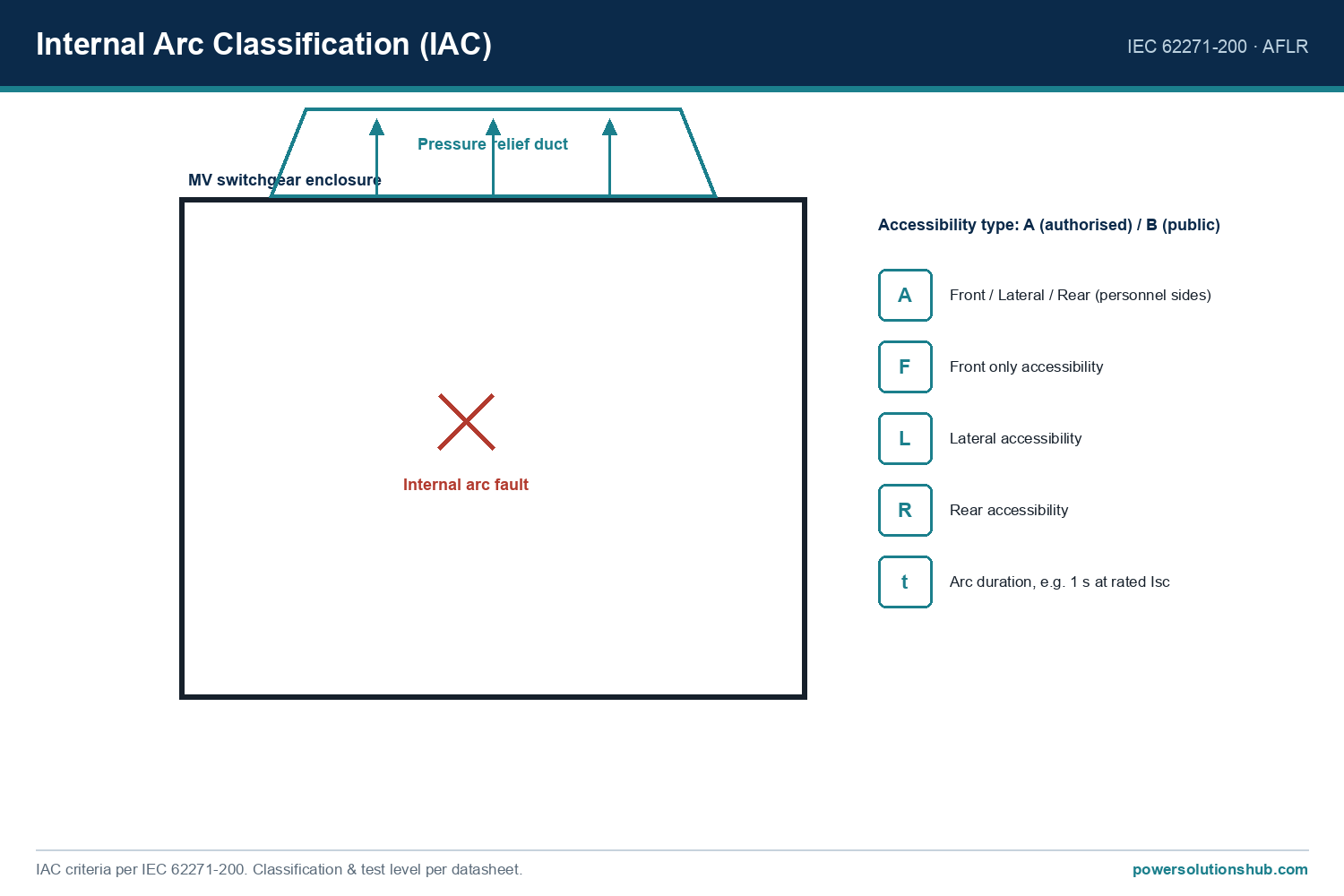
LV Circuit Breaker Sizing and Coordination

LV Circuit Breaker Sizing and Coordination: A First-Principles Engineering Guide

LV circuit breaker sizing is the engineering process of selecting a low-voltage circuit breaker’s rated current, rated short-circuit breaking capacity, and time-current trip settings so that it safely carries continuous load current, interrupts fault current within its withstand limits, and discriminates correctly with upstream and downstream devices. This guide walks through the governing formulas, a fully worked transformer-and-feeder example, a comparison table of sizing criteria, common pitfalls, and the IEC/IEEE standards that frame LV protection coordination studies. It is written for engineers and procurement teams specifying low voltage switchgear for industrial, utility, and commercial projects across the Middle East and Gulf region (including Egypt and Saudi Arabia), North Africa, CIS countries, and Sub-Saharan Africa, where ambient temperature derating and grid fault-level variation make correct breaker sizing especially important.

Correctly sized and coordinated LV breakers prevent two opposite failure modes: undersized/over-sensitive protection that trips nuisance loads or fails to carry legitimate inrush and motor-starting current, and oversized/poorly coordinated protection that lets a downstream fault escalate into an upstream trip, de-energizing far more of the installation than necessary. Both failure modes have direct cost, safety, and uptime consequences, which is why sizing and discrimination studies are a mandatory deliverable in any LV switchboard or switchgear project, and why they are normally cross-checked against the protection philosophy used for the associated [protection relay](/what-is-a-medium-voltage-protection-relay-mv-protection-relay/) settings and the upstream transformer impedance data.

LV Circuit Breaker Sizing and Coordination — schematic
LV Circuit Breaker Sizing and Coordination — schematic.

The Method: Governing Formulas for LV Breaker Sizing

LV breaker selection follows four sequential checks. A breaker is only correctly specified when it passes all four.

1. Continuous load current (In sizing). The breaker’s rated current In must be equal to or greater than the maximum continuous design current Ib of the circuit, and the cable/conductor rated current Iz must itself be equal to or greater than In — the classic IEC 60364 coordination chain:

Ib ≤ In ≤ Iz

For a three-phase load, the design current is derived from:

Ib = S / (√3 × V)

where S is the apparent power in kVA and V is the line-to-line voltage in volts.

2. Short-circuit withstand and breaking capacity. The breaker’s rated short-circuit breaking capacity (Icu or Ics) must be equal to or greater than the prospective fault current Isc at its point of installation:

Icu ≥ Isc(prospective)

Prospective fault current at a given point is commonly approximated from the upstream transformer’s rating and impedance:

Isc = In(transformer) / Z(pu)

where In(transformer) = S / (√3 × V) is the transformer’s rated secondary current and Z(pu) is the transformer impedance expressed as a per-unit (or percentage/100) value.

3. Let-through energy and thermal/mechanical withstand. For cables and busbars downstream of the breaker, the let-through energy (I²t) allowed to pass before the breaker clears the fault must not exceed the withstand of the conductor:

I²t(breaker let-through) ≤ k² × S²(conductor cross-section)

where k is a material/insulation constant from the applicable cable standard. This is the basis for selecting current-limiting breakers ahead of smaller downstream conductors.

4. Discrimination (selectivity) between series devices. Two breakers in series are said to be fully discriminative if the downstream (smaller) breaker clears any fault within its zone before the upstream breaker begins to operate. This is checked either by comparing time-current curves (time discrimination) or, for instantaneous trip devices, by comparing let-through current magnitudes (current discrimination), or by using a “zone selective interlocking” (ZSI) logic signal between the two devices’ trip units.

Selection reference
Selection reference.

Worked Example: Sizing and Coordinating a Transformer Feeder

Consider a 1000 kVA, 11 kV/415 V distribution transformer with 6% impedance, feeding an LV switchboard that in turn supplies a 250 A motor feeder.

Step 1 — Transformer secondary rated current. In(transformer) = S / (√3 × V) = 1,000,000 / (1.732 × 415) ≈ 1,391 A

Step 2 — Prospective short-circuit current at the LV main breaker. Using the simplified impedance method: Isc = In(transformer) / Z(pu) = 1,391 / 0.06 ≈ 23,190 A ≈ 23.2 kA

This means the LV main incomer breaker at the switchboard must have a rated short-circuit breaking capacity (Icu) of at least approximately 23.2 kA at the system voltage, before any network impedance reduction from cables is subtracted (in practice cable/busbar impedance between the transformer and the breaker reduces this figure somewhat, so a full fault study — not just this simplified example — should confirm the final figure).

Step 3 — Main incomer breaker current rating. Since Ib (continuous current) must be covered by In, and the transformer’s full secondary current is approximately 1,391 A, a main breaker rated at or above this value (for example, the next standard frame size above 1,391 A) is selected, subject to ambient temperature derating for the installation site.

Step 4 — Downstream feeder breaker. For the 250 A motor feeder, In(feeder breaker) ≥ Ib(feeder) = 250 A, so a breaker with a rated current at or above 250 A is chosen, with its instantaneous/short-time trip threshold set below the prospective fault current at its own busbar point but above the feeder’s expected starting inrush.

Step 5 — Discrimination check. For the main (≈1,391 A rated) and feeder (250 A rated) breakers to discriminate, the feeder breaker’s time-current curve — including its short-time and instantaneous zones — must clear faults at the 250 A feeder busbar before the main breaker’s own curve starts to operate. Where the two curves overlap at high fault current (common with instantaneous-only downstream breakers), either a short-time-delay (STD) setting is applied on the upstream breaker, or zone selective interlocking is used to guarantee selectivity up to the full prospective fault level of approximately 23.2 kA calculated in Step 2.

Sizing and Coordination Criteria — Comparison Table

Sizing criterion Governing formula / check What it protects against Typical consequence if ignored
Continuous current (In) Ib ≤ In ≤ Iz Conductor overheating, nuisance tripping Breaker trips under normal load, or cable overheats
Short-circuit breaking capacity (Icu/Ics) Icu ≥ Isc(prospective) Breaker destruction during fault interruption Breaker fails catastrophically instead of clearing fault
Let-through energy (I²t) I²t(let-through) ≤ k²S² Cable/busbar thermal damage during fault Cable insulation damage even though breaker “worked”
Discrimination (selectivity) Downstream curve clears before upstream curve Unnecessary loss of supply to healthy circuits A fault on one feeder blacks out the whole switchboard
Ambient/altitude derating In(site) = In(nameplate) × derating factor Breaker overheating in hot climates/enclosures Breaker trips below its nameplate rating in hot ambient conditions

Selection Criteria and Common Pitfalls

When specifying LV breakers for a project, engineers should work through several practical considerations beyond the four core formulas above.

Ambient temperature and enclosure derating. LV breakers are calibrated at a reference ambient temperature; installations in hot climates or in sealed cabinets without forced ventilation require a derating factor applied to the nameplate current rating. This is a frequent source of unplanned nuisance tripping in hot-climate projects across the Gulf and North Africa if the original study assumed a cooler reference temperature.

Cascading vs. full discrimination. Some designs intentionally allow “cascading,” where an upstream breaker assists a downstream breaker in clearing very high fault currents (both operate together), trading off selectivity for lower-cost downstream breakers. This must be a deliberate design decision, documented in the protection study, not an accidental consequence of mismatched curves.

Motor starting and inrush. Breakers protecting motor feeders or transformers must have a time-current curve shaped to ride through normal starting/inrush current without nuisance tripping, while still clearing genuine short-circuit and overload conditions — this is why motor circuits typically use a dedicated motor-protective curve rather than a generic thermal-magnetic curve.

Fault level growth over time. As a site’s generation or transformer capacity grows, prospective fault current at existing switchboards rises. A breaker correctly sized today can become undersized for short-circuit duty after a future transformer upgrade, so fault studies should be re-validated whenever upstream transformer or generator capacity changes.

Coordination with upstream MV protection. The LV main incomer breaker’s settings must also be checked against the upstream MV protection relay and ring main unit or switchgear fuse/relay settings feeding the transformer, so that an LV-side fault is cleared by the LV breaker first, and only escalates to MV protection if the LV breaker fails to clear it.

Test and certification basis. Icu and Ics figures quoted on a breaker’s nameplate are only valid when read together with the test standard and duty cycle under which they were verified; mixing figures from different test conditions without checking the underlying standard is a common specification error.

Standards

LV circuit breaker ratings, test duties, and coordination are governed primarily by the IEC 60947 series (low-voltage switchgear and controlgear), with IEC 60947-2 specifically addressing circuit breakers, and the overall installation design and cable/breaker coordination chain (Ib ≤ In ≤ Iz) codified in IEC 60364 (low-voltage electrical installations). Equivalent North American practice follows IEEE and UL/NEMA frameworks for molded-case and insulated-case breakers. Project specifications should always state which standard’s test duty cycle the quoted Icu/Ics breaking capacity was verified under.

Related guides

See also our guides on medium voltage switchgear, gas-insulated switchgear and metal-clad switchgear.

What is the difference between Icu and Ics on an LV breaker?

Icu is the rated ultimate short-circuit breaking capacity — the maximum fault current the breaker can interrupt, verified under a test sequence after which the breaker is not required to remain fully serviceable. Ics is the rated service short-circuit breaking capacity, expressed as a percentage of Icu, confirming the breaker remains serviceable after clearing that fault level — a more demanding practical requirement for breakers expected to continue operating after a fault.

How do I calculate prospective short-circuit current for LV breaker sizing?

In its simplest form, prospective fault current downstream of a transformer is estimated as the transformer’s rated secondary current divided by its per-unit impedance (Isc = In/Zpu), as shown in the worked example above. A full study also subtracts the impedance contribution of cables, busbars, and any upstream network impedance for a more precise figure.

Why do two breakers in series sometimes both trip for the same fault?

This happens when their time-current curves overlap at the fault’s current magnitude — usually because both have instantaneous trip elements set too close together, or because the upstream breaker lacks a short-time-delay setting. The fix is either to add a short-time-delay function on the upstream breaker or implement zone selective interlocking between the two trip units.

Does ambient temperature really change a breaker’s effective current rating?

Yes. Thermal-magnetic and many electronic trip units are calibrated against a stated reference ambient temperature; operating in a hotter ambient or an enclosed, poorly ventilated panel reduces the breaker’s effective current-carrying capacity, which is why a derating factor must be applied during sizing for hot-climate installations.

Can I use the same breaker type for both the main incomer and feeder circuits?

Technically yes, but it is rarely optimal. Main incomers typically need higher continuous current and short-circuit ratings along with short-time-delay settings for selectivity, while feeder breakers are chosen for the specific downstream load’s continuous current, inrush characteristic, and let-through energy limit — so feeder and incomer breakers are usually different frame sizes or trip-unit types even within the same switchboard.

What happens if I undersize a breaker’s short-circuit breaking capacity?

If the prospective fault current at the installation point exceeds the breaker’s rated breaking capacity (Icu), the breaker may fail to safely interrupt the fault, risking internal arcing, enclosure damage, or failure to clear the fault at all — this is why the short-circuit check (Icu ≥ Isc) is treated as a hard pass/fail criterion, not an optimization.

How does LV breaker coordination relate to the upstream MV switchgear and transformer?

The LV main breaker’s settings are normally chosen so that LV-side faults are cleared entirely within the LV switchboard, with the MV protection relay and switchgear acting only as a backup if the LV breaker fails to operate — this requires the LV and MV protection studies to be coordinated together rather than specified independently.

Looking for medium voltage switchgear?

Looking for high-quality medium voltage switchgear? We provide expert engineering support and reliable products for all your medium voltage needs.

For quotations and requests: info@electricistanbul.com

WhatsApp: +90 501 076 69 91