
An MV cable termination is the engineered interface that connects a shielded medium-voltage power cable to switchgear, a transformer bushing, or an overhead line, restoring electrical stress control, insulation integrity, and mechanical sealing at the cable end. Correct termination selection and sizing is a first-principles exercise that combines the system’s rated voltage class, the cable’s conductor cross-section and insulation type, the expected load and short-circuit current, and the installation environment (indoor dry-type cabinet, outdoor pole, or oil-filled transformer compartment). This guide walks through the governing formulas, a fully worked numerical example, a practical comparison table, and the IEC standards that govern termination design, so that specifying engineers across the Middle East and Gulf region including Egypt and Saudi Arabia, North Africa, the CIS states, and Sub-Saharan Africa can standardize their termination selection process for export and EPC projects.
Why Termination Selection Matters
A cable termination is not a passive accessory — it is the single highest-stress point in an MV cable system. At the cut end of a shielded cable, the uniform radial electric field that exists along the cable body is abruptly interrupted when the semi-conducting screen stops, creating a concentrated stress point unless it is controlled by a stress cone, pre-molded stress-control component, or heat-shrink stress tube. An undersized or incorrectly selected termination can lead to partial discharge, insulation tracking, and eventual flashover — often the root cause of MV cable failures in the field rather than the cable body itself. Selecting the termination therefore means matching three independent parameters simultaneously: the system voltage class, the conductor ampacity, and the mechanical/environmental duty (indoor vs outdoor, oil-immersed vs air-insulated), while also confirming the let-through short-circuit current the termination’s clamp and lug must survive.
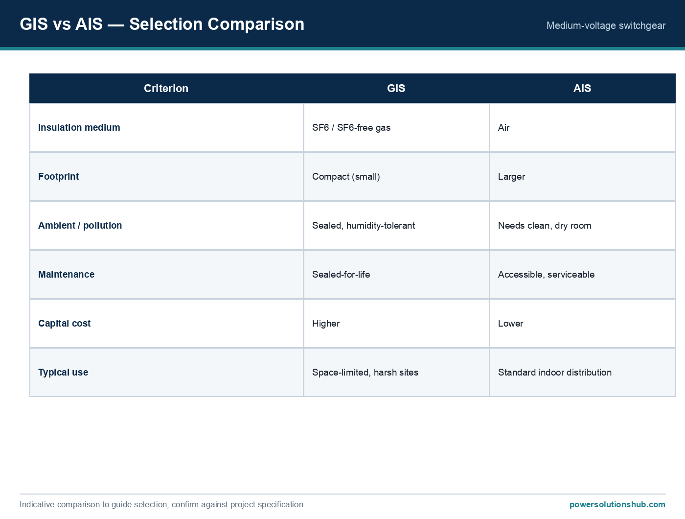
For background on the switchgear bays these terminations usually connect into, see our MV switchgear hub and [protection relay](/what-is-a-medium-voltage-protection-relay-mv-protection-relay/) guides; terminations into transformer bushings are covered conceptually in our transformer resources.
The Method: Formulas Governing Termination Sizing
Termination sizing follows four sequential calculation steps.
Step 1 — Rated current (ampacity check). The rated/load current that the termination’s lug and connector must carry continuously is derived from the system’s apparent power and voltage:
I = S / (√3 × V)
where I is the line current in amps, S is apparent power in kVA, and V is the rated line-to-line voltage in kV. The termination’s compression lug and connector size must be selected for the cable’s conductor cross-section at or above this current, with sufficient thermal margin for the insulation class.
Step 2 — Short-circuit thermal withstand. The cable conductor and termination clamp must survive the fault current for the duration the upstream protection takes to clear it. The adiabatic short-circuit formula for conductor thermal withstand is:
I_sc × √t = k × A
where I_sc is the fault current in kA, t is the fault clearing time in seconds, A is the conductor cross-sectional area in mm², and k is a material constant for the conductor/insulation combination. Rearranged, the maximum allowable fault duration for a given conductor size and fault level is:
t = (k × A / I_sc)²
Step 3 — Dielectric/BIL compatibility. The termination’s rated voltage class and basic insulation level (BIL) must be equal to or greater than the system’s nominal and lightning-impulse withstand requirements. This is a direct one-to-one match against the switchgear or transformer bushing rating — a termination can never be “upgraded” electrically beyond its own insulation design.
Step 4 — Creepage distance for outdoor/polluted environments. For outdoor terminations, the minimum creepage distance (surface leakage path, in mm) is obtained by multiplying the system’s phase-to-phase voltage (in kV) by a pollution-severity factor (mm/kV) selected per the site’s pollution class (light, medium, heavy, or very heavy), as defined in IEC 60815. Coastal, desert-dust, and industrial sites typically require a heavier pollution class and therefore a longer creepage path than a clean indoor cabinet.
Worked Example: Sizing a Termination for an 11 kV Feeder
Consider a 1000 kVA distribution transformer feeder operating at 11 kV, protected by an upstream relay with a fault-clearing time of 0.5 seconds, and a prospective fault level of 20 kA at the termination point. We will size the termination’s current rating, verify thermal withstand, and determine the minimum outdoor creepage distance.
Step 1 — Rated current. I = S / (√3 × V) = 1,000 / (1.732 × 11) ≈ 1,000 / 19.05 ≈ 52.5 A
For example, at this 52.5 A load current, a termination kit rated for the cable’s conductor size (e.g., 50–95 mm² depending on cable selection) with ample thermal margin above 52.5 A would be selected — not a kit sized at the bare minimum, to allow for ambient temperature derating and future load growth.
Step 2 — Short-circuit thermal check. Using the adiabatic formula with an illustrative copper conductor constant k ≈ 143 (A·s^0.5/mm², a commonly cited reference value for XLPE-insulated copper conductors) and a 95 mm² conductor:
Maximum withstand current for t = 0.5 s: I_sc(max) = k × A / √t = (143 × 95) / √0.5 ≈ 13,585 / 0.707 ≈ 19,215 A ≈ 19.2 kA
For example, comparing this to our assumed fault level of 20 kA shows the 95 mm² conductor/termination combination is marginally undersized for a 0.5 s clearing time — the engineer would either upsize the conductor/termination to 120 mm², or confirm the protection relay can clear the fault faster (e.g., at 0.3 s instead of 0.5 s):
I_sc(max) at 0.3 s = (143 × 95) / √0.3 ≈ 13,585 / 0.548 ≈ 24,790 A ≈ 24.8 kA
This second calculation shows that reducing the clearing time to 0.3 s brings the withstand comfortably above the 20 kA fault level, illustrating the direct trade-off between conductor/termination size and protection relay speed — a coordination exercise that should always be cross-checked against your protection relay settings.
Step 3 — Dielectric check. An 11 kV system requires a termination rated for at least the equivalent voltage class with adequate BIL margin for lightning/switching impulses — this is a straightforward nameplate match against the switchgear bay or transformer bushing rating.
Step 4 — Outdoor creepage (if applicable). For an outdoor termination on this 11 kV feeder in a medium pollution zone, the creepage distance is calculated as phase-to-phase voltage (kV) × pollution factor (mm/kV per IEC 60815 pollution class), giving the minimum acceptable surface leakage path in mm for the selected termination kit. The exact mm/kV factor must be taken from the site-specific pollution class table rather than assumed generically.
Selection and Comparison Table
| Selection Criterion | Key Question | Typical Consequence if Ignored |
|---|---|---|
| Voltage class / BIL | Does termination rating ≥ system nominal + impulse withstand? | Flashover under lightning/switching surge |
| Conductor ampacity | Is lug/connector sized ≥ calculated I = S/(√3·V)? | Overheating, lug oxidation, hot-spot failure |
| Short-circuit withstand | Does I_sc·√t ≤ k·A hold for the relay clearing time? | Conductor/termination burn-back under fault |
| Indoor vs outdoor type | Dry cabinet, open-air pole, or oil-immersed bushing? | Moisture ingress, tracking, premature ageing |
| Cable insulation type | XLPE, EPR, or paper-insulated (PILC)? | Incompatible stress-control component, PD |
| Termination technology | Heat-shrink, cold-shrink, or pre-molded push-on? | Installation defects, inconsistent stress control |
| Environmental pollution class | Light, medium, heavy, or very heavy per IEC 60815? | Insufficient creepage, surface flashover |
| Single-core vs three-core cable | Does geometry match stress-cone/cable-gland design? | Poor sealing, screen bonding errors |
Selection Criteria and Common Pitfalls
Match the termination to the cable insulation system. Stress-control components (pre-molded stress cones, heat-shrink stress tubes, or cold-shrink modules) are engineered specifically for XLPE, EPR, or legacy paper-insulated lead-covered (PILC) cables. Mixing technologies — for instance, fitting an XLPE-rated stress cone onto a PILC cable — compromises the electric field grading and is a frequent cause of premature failure.
Never oversize the ampacity margin away from fault duty. It is tempting to select the largest available termination lug “for safety,” but oversized lugs on undersized conductors create a thermal mismatch at the crimp interface. The lug, connector, and conductor cross-section must be sized as a matched set per the manufacturer’s crimping/compression die chart.
Account for indoor/outdoor and oil-immersed duty separately. A termination destined for a switchgear cable box (dry, indoor, pollution-controlled) has very different creepage and sealing requirements from one terminating into an oil-filled transformer bushing well, or one mounted outdoors on a pole in a dusty, coastal, or desert environment. Confirm the duty type before finalizing the IEC 60815 pollution class assumption.
Re-verify short-circuit coordination whenever protection settings change. The I_sc·√t calculation in Step 2 is only valid for the specific relay clearing time assumed. If protection coordination studies are revised — for example, after adding new downstream feeders — the termination’s short-circuit thermal withstand must be re-checked against the new clearing time.
Confirm screen/earthing continuity. Cable screens must be correctly bonded and earthed at the termination per the system’s earthing philosophy (solid, single-point, or cross-bonded for long circuits), since incorrect screen bonding can introduce circulating currents or leave the screen floating at a hazardous potential.
Standards Governing MV Cable Terminations
MV cable termination design, testing, and type approval are principally governed by the IEC 60502 series (“Power cables with extruded insulation and their accessories for rated voltages from 1 kV up to 30 kV”), which addresses cable and accessory (including termination) construction and test requirements for this voltage range. Outdoor insulator and termination creepage/pollution performance is addressed by IEC 60815 (“Selection and dimensioning of high-voltage insulators for polluted conditions”). Where terminations interface with switchgear cable boxes, the switchgear’s own enclosure and arc-fault classification is governed separately by the IEC 62271 switchgear series, but this applies to the switchgear enclosure itself, not the termination component. Always confirm the specific sub-part and edition applicable to the project’s voltage class and cable construction with the termination manufacturer’s type-test certificates.
Related guides
See also our guides on medium voltage switchgear, gas-insulated switchgear and ring main units.
What is the difference between heat-shrink, cold-shrink, and pre-molded terminations?
Heat-shrink terminations use a flame or heat gun to shrink a stress-control tube onto the prepared cable end; cold-shrink terminations are pre-expanded over a removable core and shrink at ambient temperature once the core is withdrawn, requiring no open flame; pre-molded (push-on) terminations are factory-manufactured silicone or EPDM components slid directly onto the prepared cable. Each technology has different installation skill requirements and is suited to different site conditions (e.g., cold-shrink for hazardous-area or confined installations where open flame is restricted).
How do I know if I need an indoor or outdoor termination?
The choice depends on where the cable end actually terminates: inside a switchgear cable compartment or dry transformer cable box calls for an indoor-type termination, while a cable rising to an overhead line, pole-mounted transformer, or any exposed outdoor connection requires an outdoor-type termination with appropriate creepage distance and weather sealing per IEC 60815.
Can I use the same termination for single-core and three-core cables?
No. Single-core and three-core cable terminations use different stress-control geometries and gland/sealing designs because the screen bonding, phase separation, and mechanical entry point differ fundamentally between the two cable constructions.
What happens if the termination’s short-circuit withstand is lower than the system’s fault level?
The conductor or termination clamp can overheat and mechanically fail during a through-fault, even if the fault is cleared within the protection relay’s normal operating time, because the adiabatic thermal limit (I_sc·√t ≤ k·A) is exceeded — this is why Step 2 of the sizing method above must always be checked against actual relay coordination settings.
Does termination sizing depend on the switchgear or only on the cable?
Both. The cable determines conductor size, insulation type, and screen construction, while the switchgear or transformer bushing determines the voltage class, BIL, and physical interface (bushing well, cable box clearance) that the termination must match at both ends.
How does pollution class affect termination selection?
In coastal, desert, or industrial sites with airborne salt, dust, or chemical contamination, surface leakage currents across an outdoor termination’s insulating surface increase, requiring a longer creepage distance per the IEC 60815 pollution-severity classification to avoid surface tracking and flashover.
Is a PILC-to-XLPE transition termination different from a standard termination?
Yes. Transition terminations (also called “transition joints” when mid-span) are specifically engineered to manage the different insulation characteristics, screen types, and stress-control requirements between legacy paper-insulated and modern extruded-dielectric cables, and must never be substituted with a standard single-technology termination kit.
Looking for medium voltage cable terminations?
Looking for high-quality medium voltage cable terminations? We provide expert engineering support and reliable products for all your medium voltage needs.
For quotations and requests: info@electricistanbul.com
WhatsApp: +90 501 076 69 91