Arc Flash Study and Calculation for MV Switchg

Arc Flash Study and Calculation for MV Switchgear: Methods, Formulas, and a Worked Example

An arc flash study is the engineering analysis that quantifies the incident energy and safe working boundaries released by a potential internal arcing fault in electrical equipment, so that personnel protective equipment (PPE), labeling, and switchgear design can be correctly specified. For medium-voltage (MV) switchgear, this study combines a short-circuit current calculation with an arc-energy model to determine how much thermal energy a worker could be exposed to at a given working distance and fault-clearing time. This guide walks through the calculation method step by step, with a fully worked numerical example, a comparison table, selection guidance, and the governing IEC/IEEE standards. It is written for utility, EPC, and industrial engineers specifying or auditing MV switchgear across the Middle East and Gulf region (including Egypt and Saudi Arabia), North Africa, CIS countries, and Sub-Saharan Africa, where new substations and retrofit projects increasingly require documented arc flash risk assessments as part of tender specifications.
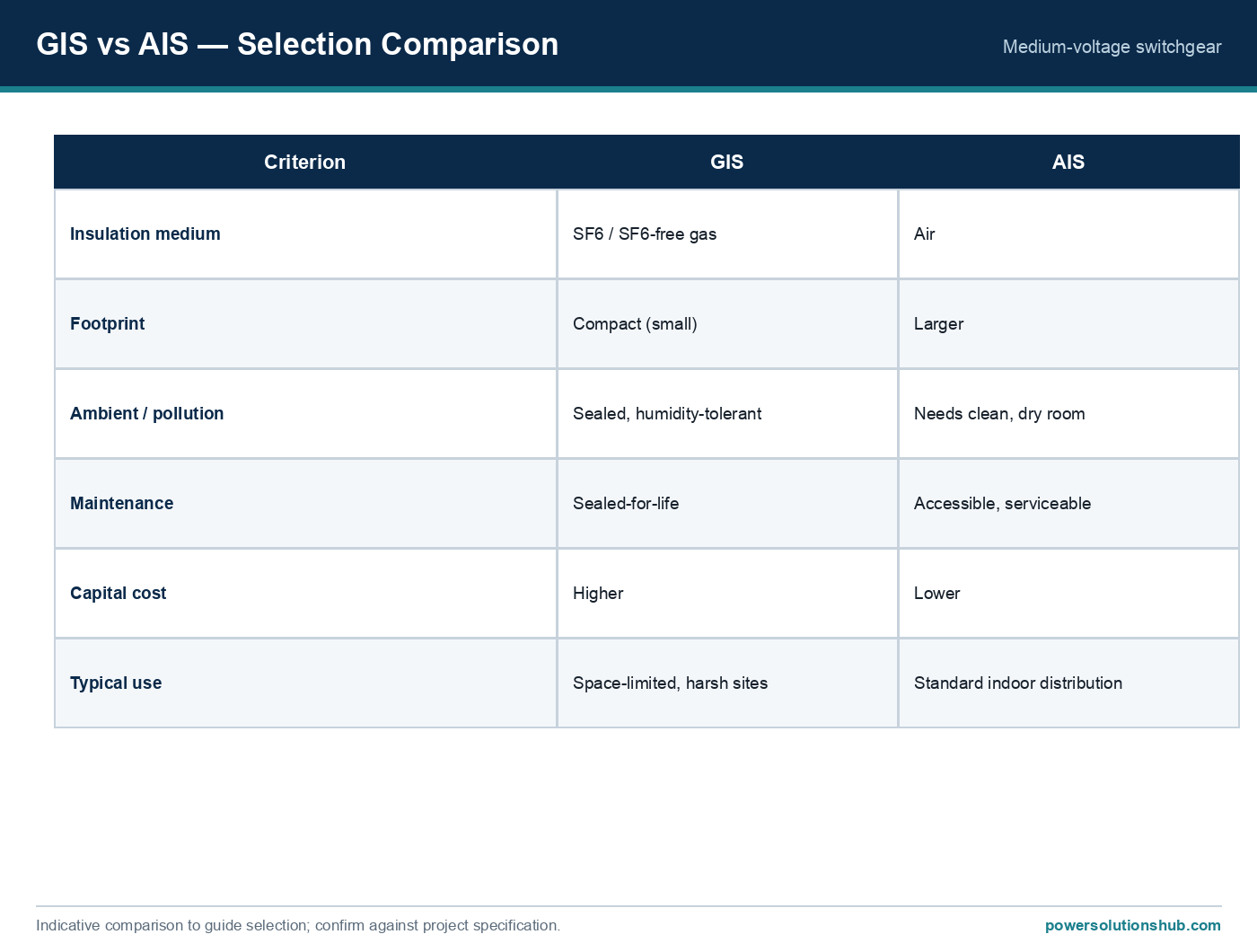
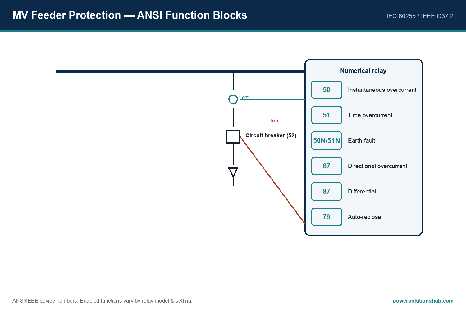
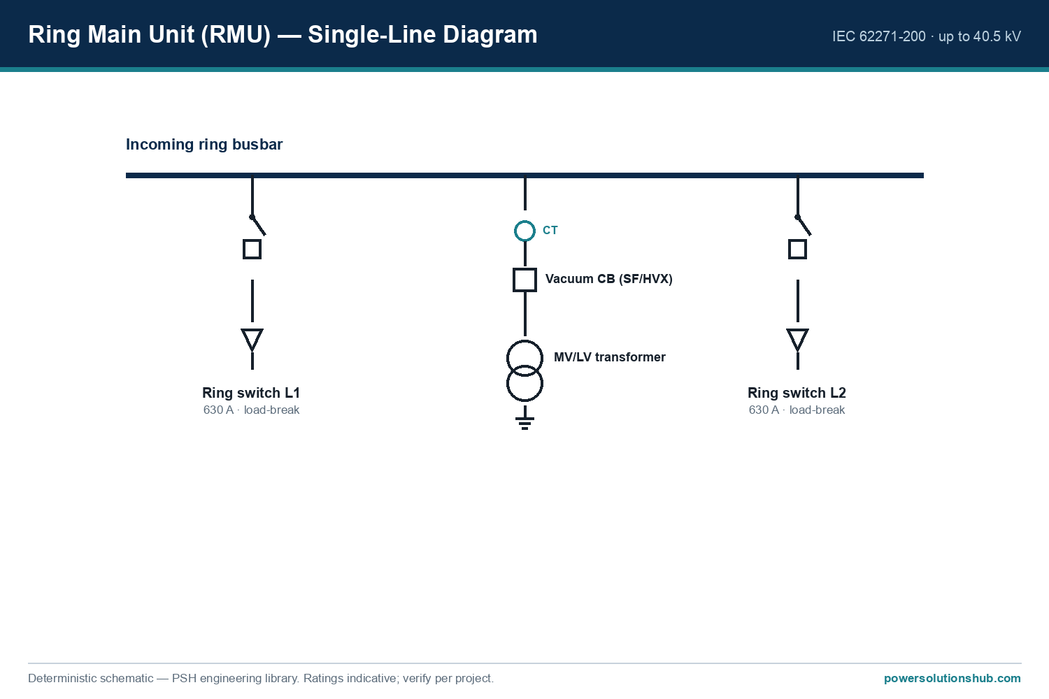
Arc Flash Study and Calculation for MV Switchg — schematic
Arc Flash Study and Calculation for MV Switchg — schematic.

Why the arc flash study matters

An internal arcing fault inside MV switchgear releases energy far beyond that of a normal bolted short circuit because the arc itself adds resistance and radiates heat, light, and pressure into the surrounding air. Unlike low-voltage arc flash incidents, MV arcing faults can sustain very high currents for the full duration of the protection relay‘s clearing time, so the resulting incident energy at typical working distances can be severe. The purpose of the study is threefold: (1) to select the correct PPE category and boundary distances for switching, racking, and testing operations; (2) to justify design mitigation such as arc-resistant (IAC-classified) switchgear enclosures, arc-flash relays, or remote racking; and (3) to support relay coordination decisions that reduce clearing time, which has a direct, near-linear effect on incident energy.
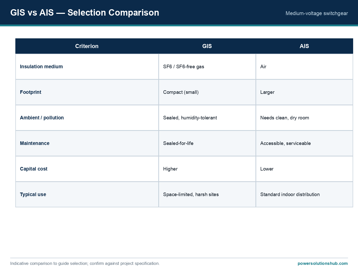
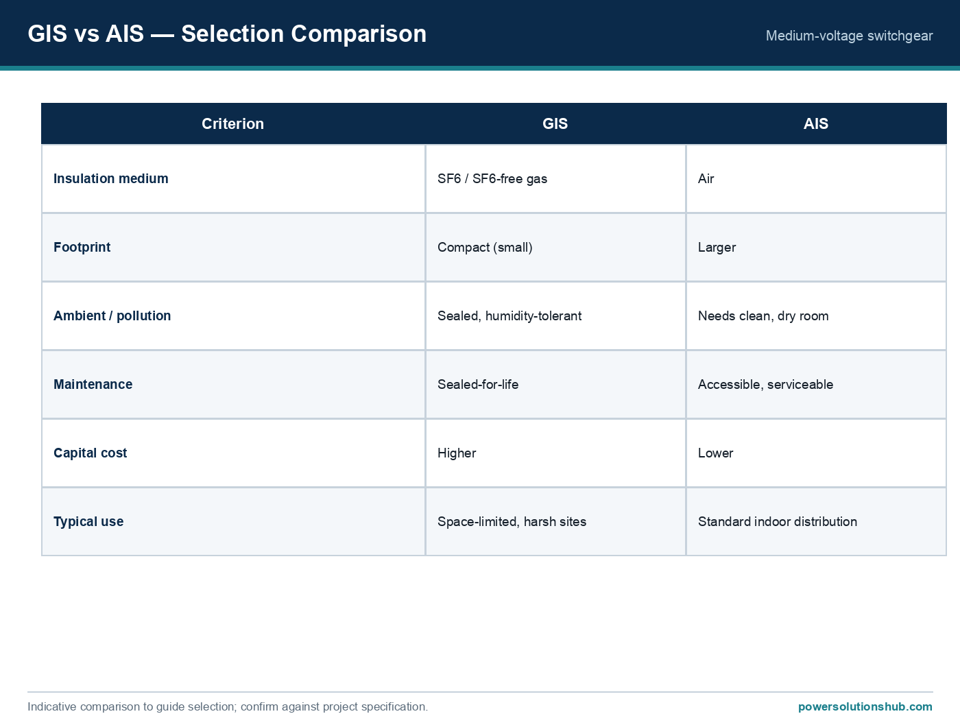
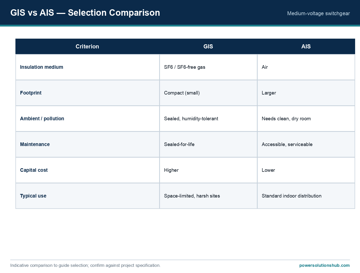
Selection reference
Selection reference.

The calculation method

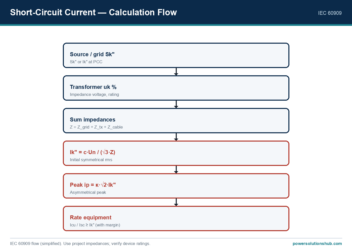
An arc flash study for MV switchgear is performed in three sequential steps.

Step 1 — Bolted (three-phase) short-circuit current, per IEC 60909. The available bolted fault current at the switchgear busbar is calculated from the source impedance (utility grid, generator, and transformer impedances reflected to the bus voltage), following the IEC 60909 short-circuit calculation method. This gives the initial symmetrical short-circuit current, Ik″, which is the starting point for the arc flash model.

Step 2 — Arcing current. An arcing fault draws less current than a bolted fault because the arc itself introduces impedance. Empirical arc flash models (notably IEEE 1584) derive an arcing current, Ia, as a function of the bolted fault current, system voltage, and the electrode gap of the equipment. As a general engineering rule of thumb used in MV arc flash screening, the arcing current is commonly on the order of 85–95% of the bolted fault current, though the exact ratio depends on voltage class and equipment geometry and should be taken from the applicable arc-current equation rather than assumed.

Step 3 — Incident energy. Incident energy (typically expressed in cal/cm²) is calculated from the arcing current, the total protection clearing time (relay pickup + breaker interrupting time), the working distance from the potential arc source, and an equipment/enclosure correction factor. The relationship is approximately proportional to arcing current, proportional to clearing time, and inversely proportional to the square of the working distance — which is why reducing clearing time and increasing working distance are the two most effective mitigation levers available to the design engineer.

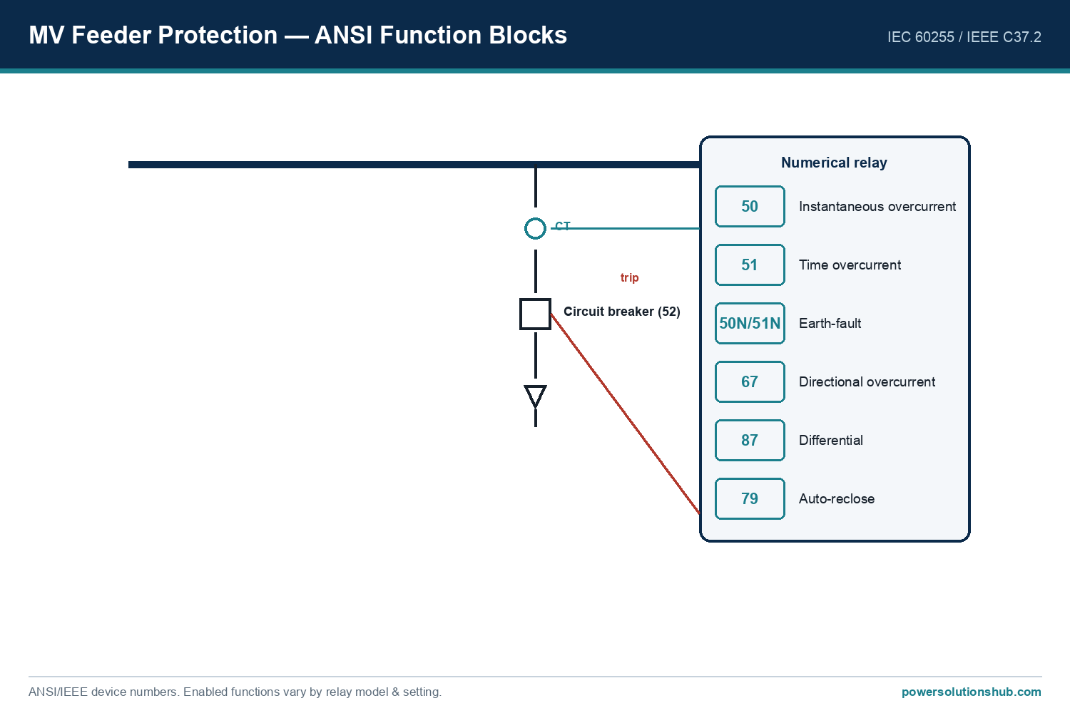
Internal reference material on protection relay coordination is available on our protection relay hub page, and on transformer impedance data on our distribution transformer hub page, both of which feed directly into Steps 1 and 3 above.

Worked example

Consider an 11 kV MV switchboard fed through a 1000 kVA distribution transformer, with an upstream grid fault level of 500 MVA at the 11 kV busbar.

Rated current of the transformer secondary: I = S / (√3 × V) = 1,000,000 / (1.732 × 11,000) ≈ 52.5 A

Bolted fault current at the 11 kV bus (from grid fault level): Ibf = Ssc / (√3 × V) = 500,000,000 / (1.732 × 11,000) ≈ 26,247 A ≈ 26.2 kA

Estimated arcing current (using an illustrative 90% ratio for MV switchgear, per the general relationship described in Step 2 above): Ia ≈ 0.90 × 26.2 kA ≈ 23.6 kA

Clearing time: assume the protection relay and circuit breaker combination clears the fault in 0.3 seconds (typical for a coordinated MV feeder protection scheme with time-graded overcurrent settings).

Working distance: assume a standard 610 mm (24 in) working distance for a worker at the switchgear front panel during a racking or switching operation.

Using the general IEEE 1584 relationship that incident energy scales with arcing current and time and inversely with the square of working distance, an illustrative incident energy for this scenario — calculated per the full IEEE 1584-2018 equipment-class-specific formula — would need to be run through the standard’s published coefficients for the exact enclosure type and gap distance; the example above illustrates only the input variables an engineer must gather (bolted fault current, arcing current, clearing time, and working distance) before that formula is applied. The key takeaway is that halving the clearing time — for example, from 0.3 s to 0.15 s through faster relay coordination — roughly halves the resulting incident energy, while doubling the working distance reduces it by roughly a factor of four.

Worked example — summary table

Parameter Symbol Formula / Basis Value
System voltage V Given 11 kV
Transformer rating S Given 1000 kVA
Transformer rated current I S/(√3×V) ≈ 52.5 A
Upstream fault level Ssc Given 500 MVA
Bolted fault current Ibf Ssc/(√3×V), per IEC 60909 ≈ 26.2 kA
Estimated arcing current Ia ≈0.90 × Ibf (illustrative ratio) ≈ 23.6 kA
Protection clearing time t Relay + breaker interrupting time 0.3 s (example)
Working distance D Standard front-panel exposure 610 mm
Incident energy E Per IEEE 1584 equipment-class equation Requires full IEEE 1584 formula with enclosure/gap coefficients

Selection criteria and common pitfalls

Use arcing current, not bolted current, for the energy calculation. Using the bolted fault current directly (skipping Step 2) overstates or understates incident energy depending on system characteristics and is a frequent audit finding.

Get the clearing time right, including relay pickup and breaker interrupting time. Because incident energy scales roughly linearly with clearing time, an arc flash study performed with outdated relay settings after a protection upgrade will misstate the actual hazard — the study must be re-run whenever protection coordination changes.

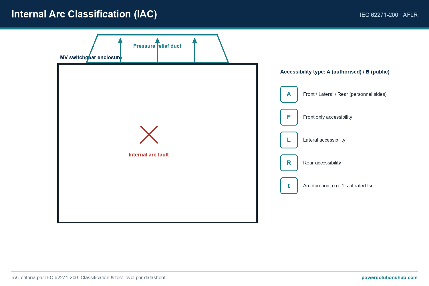
Specify arc-resistant (IAC-classified) switchgear where personnel access is required during energized conditions. Internal arc classification (IAC) testing under IEC 62271-200 verifies that a switchgear enclosure can contain and vent the effects of an internal arcing fault away from the operator’s normal standing position, which is a design mitigation independent of — but complementary to — the PPE-based arc flash study.

Consider arc-flash detection relays for high-energy applications. Optical or pressure-based arc detection can cut clearing time to a fraction of a standard overcurrent relay’s response, delivering the largest single reduction in incident energy achievable at the protection level.

Re-validate the study after any system change. Adding generation, changing transformer impedance, reconfiguring bus ties, or upgrading protection settings all change the bolted fault current, the arcing current, or the clearing time — any of which invalidates a previous study.

Match working distance assumptions to actual operating tasks. Racking a withdrawable circuit breaker, inserting test plugs, or opening a cable compartment door each expose personnel at different distances; the study should reflect the closest realistic exposure for each task, not a single generic distance.

Governing standards

The arc flash calculation methodology itself is defined by IEEE 1584 (Guide for Performing Arc Flash Hazard Calculations), which provides the empirical equations for arcing current and incident energy referenced in this guide. The upstream short-circuit current used as an input is calculated per IEC 60909 (Short-circuit currents in three-phase AC systems). Where the switchgear enclosure itself is intended to contain and vent an internal arcing fault, the relevant equipment standard is IEC 62271-200 (AC metal-enclosed switchgear and controlgear for rated voltages above 1 kV and up to and including 52 kV), which defines the internal arc classification (IAC) test procedure and accessibility types. Related testing guidance for internal arc effects is also addressed in IEC 61641. Engineers should confirm which of these standards is referenced in the project’s technical specification, since utilities and EPC contractors in different regions may cite different editions or combinations.

For background on the switchgear types these studies are typically performed on, see our [medium voltage switchgear](https://powersolutionshub.com/what-is-mv-switchgear-medium-voltage-switchgear/) hub page.

Related guides

See also our guides on gas-insulated switchgear, ring main units and metal-clad switchgear.

What is the difference between an arc flash study and a short-circuit study?

A short-circuit study (per IEC 60909) calculates the available bolted fault current at each bus in the system. An arc flash study uses that fault current as an input, together with arcing current, clearing time, and working distance, to calculate the incident energy a worker could be exposed to — it is a downstream analysis that depends on the short-circuit study being current and accurate.

Does arc flash risk apply to MV switchgear or only to low-voltage panels?

Arc flash hazards apply across all voltage classes, including MV switchgear. In fact, MV arcing faults can sustain higher fault currents for longer durations than typical LV panels, which is why arc-resistant (IAC) switchgear design and arc-flash relay protection are commonly specified for MV applications with routine personnel access.

How often should an arc flash study be updated?

The study should be reviewed whenever the electrical system changes in a way that affects fault current or clearing time — new generation or transformers, protection relay setting changes, bus reconfiguration, or utility fault-level revisions — and periodically reviewed as part of routine electrical safety audits even without known changes.

What is IAC classification and how does it relate to arc flash studies?

Internal Arc Classification (IAC), defined under IEC 62271-200, is a switchgear design verification confirming the enclosure can withstand and vent an internal arcing fault without endangering an operator standing in a defined accessibility zone. It is a complementary mitigation to the arc flash study: the study quantifies residual risk and PPE requirements, while IAC-rated equipment reduces the underlying hazard at its source.

Can reducing the protection clearing time reduce arc flash risk without changing the switchgear?

Yes. Because incident energy is approximately proportional to clearing time, faster protection response — through optimized relay coordination, differential protection, or dedicated arc-flash detection relays — can significantly reduce calculated incident energy without any change to the switchgear enclosure itself.

Who typically performs an arc flash study for MV switchgear?

Arc flash studies are typically performed by protection and power systems engineers using dedicated short-circuit and arc-flash calculation software that implements the IEEE 1584 equations, supported by accurate single-line diagrams, transformer impedance data, and relay coordination settings from the project’s protection study.

What working distance should be used for MV switchgear when no site-specific data is available?

In the absence of manufacturer- or site-specific data, engineers commonly use standard reference working distances associated with typical operator positions during switching, racking, or test-plug insertion tasks, as defined in the arc flash calculation standard being applied; these distances should always be verified against the actual task and equipment geometry rather than assumed by default.

Looking for medium voltage switchgear?

Looking for high-quality medium voltage switchgear? We provide expert engineering support and reliable products for all your medium voltage needs.

For quotations and requests: info@electricistanbul.com

WhatsApp: +90 501 076 69 91

ABB Safeplus RMU Switchgear

ABB Safeplus RMU Switchgear

The ABB SafePlus is a sealed, gas-insulated medium-voltage ring main unit (RMU) for secondary distribution. Safeplus RMU switchgear refers to ABB’s SafePlus 36 platform — a sealed, gas-insulated medium-voltage switchgear built on the same secondary-distribution architecture as ABB SafeRing, but engineered for higher flexibility, modularity, and higher ratings within a ring main unit (RMU) configuration. This article covers the design philosophy, functional variants, technical specifications, applicable IEC standards, and buyer selection criteria for the SafePlus range, drawn directly from ABB’s official SafeRing/SafePlus 36 catalog. For procurement teams sourcing medium-voltage distribution equipment across the Middle East and Gulf (including Egypt and Saudi Arabia), North Africa, CIS, and Sub-Saharan Africa, understanding the SafePlus platform’s construction and compliance basis is essential before specifying it into a substation or compact secondary substation (CSS) project.

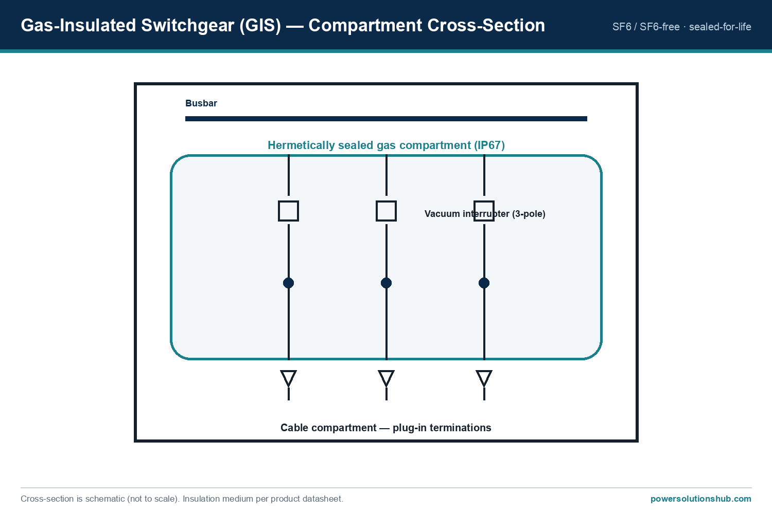
ABB Safeplus RMU Switchgear — schematic
ABB Safeplus RMU Switchgear — schematic.

What Is Safeplus RMU Switchgear?

SafePlus is part of the SafeRing/SafePlus product family, originally developed by ABB in Skien, Norway, and introduced to the market in 2000, replacing the earlier SF6-insulated RGC and CTC product lines. Since then, the combined installed base of SafeRing and SafePlus switchgear has grown to more than 150,000 units deployed across more than 100 countries worldwide.

Both SafeRing and SafePlus share the same user interface and the same underlying philosophy: functions such as earthing, disconnecting, cable connection, busbar extension, protection, and switching are integrated into compact, sealed functional units rather than built from traditional open switching cells. The key distinction is that SafeRing is delivered in standardized, high-volume, pre-defined RMU configurations intended for fast delivery, while SafePlus is the flexible, modular version of the same platform, offering customized switchgear configurations and higher electrical capacity, including smart RMU configurations for advanced grid automation.

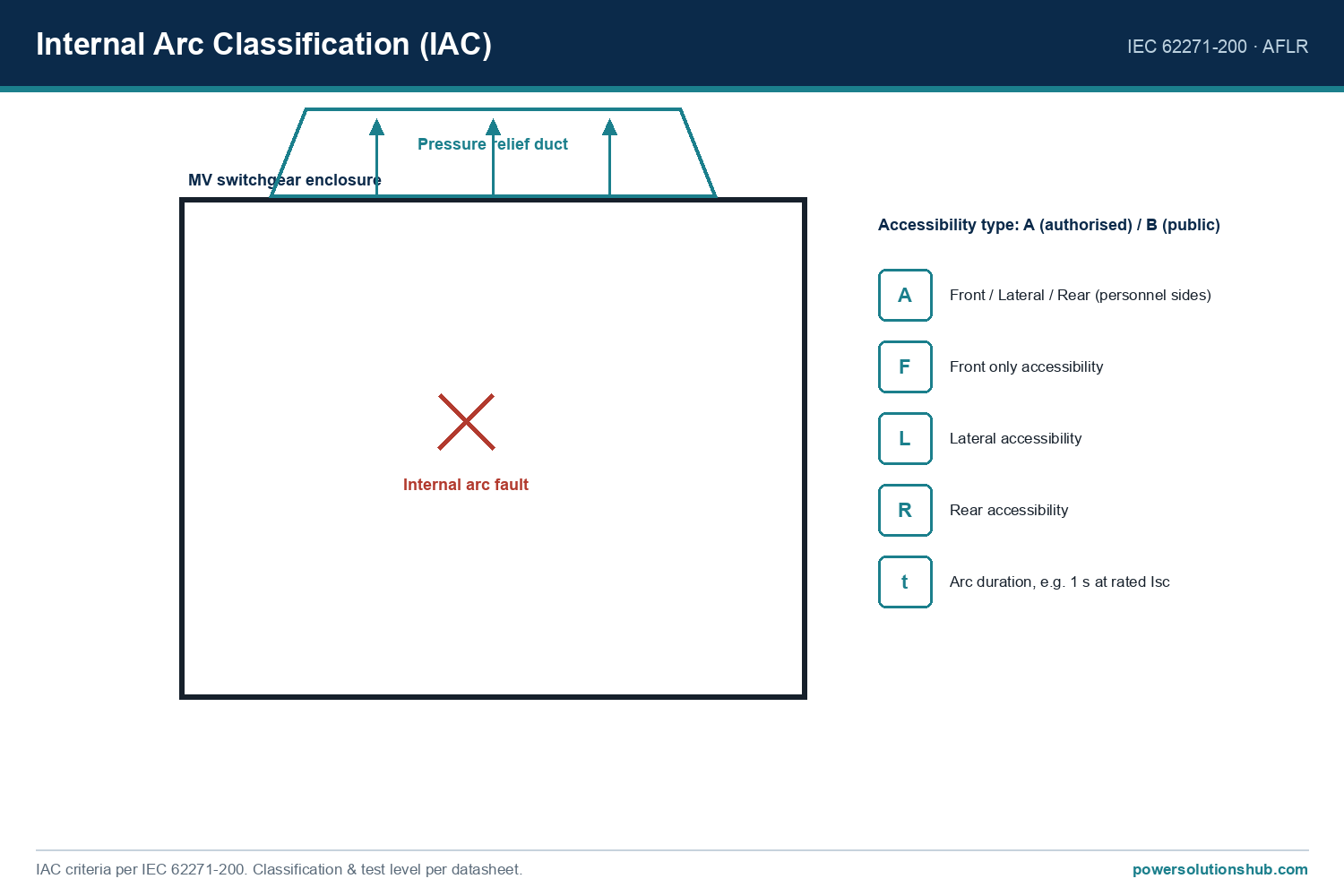
Selection reference
Selection reference.

Design and Construction

The defining characteristic of SafePlus is its completely sealed switchgear tank. All live parts and switching functions are contained inside a welded stainless steel enclosure filled with SF6 gas, which serves as both the insulation and arc-quenching medium. This sealed-for-life design is rated for an operating lifetime better than 30 years, with a gas leakage rate of less than 0.1% per year. Every enclosure is helium-leak-tested inside a vacuum chamber before being filled with SF6, and all welding is carried out by computer-controlled robots to guarantee a reliable, tight seal.

The SF6 enclosure itself carries a degree of protection of IP67, meaning it can be immersed in water and still maintain full functionality. This makes the switchgear well suited to humid, coastal, or climatically demanding environments typical of GEO export markets.

Externally, the upper and lower front covers are made of 1.5 mm aluzink sheet finished with a polycarbonate foil carrying the mimic diagram and switch position indicators, while side covers are made of 1.25 mm hot-rolled steel, powder-painted in RAL 7035. Cable compartments are separated by partition walls, and in switchgear with the IAC AFL arc-proof classification, a vertical partition wall keeps hot gases from an internal arc away from the cable compartment; in the AFLR classification, hot gases are permitted to reach the cable compartment.

Low-voltage compartments are available in three configurations — integrated with the front cover, integrated with a hinged door, or a high version with a hinged door. In the high LV compartment version, the total switchgear height reaches 2180 mm, rising to 2280 mm when a metering module is included.

SafeRing vs SafePlus: Positioning Within the Range

Attribute SafeRing SafePlus
Configuration philosophy Standardized, pre-defined, high-volume Flexible, modular, customized
Typical use case Fast-delivery transformer/switching stations, DSO consumer switchgear Advanced distribution needs, including smart RMUs / grid automation
Electrical capacity Standard ratings Higher ratings, more functional flexibility
User interface Same as SafePlus Same as SafeRing
Sealed system Yes, stainless steel, sealed-for-life Yes, stainless steel, sealed-for-life

Both products come from the same engineering platform, and buyers should treat the choice between them as a question of standardization versus configurability rather than a difference in core safety technology.

Key Technical Data

Parameter Value
Installed base >150,000 units, >100 countries
Sealed system operating lifetime Better than 30 years
SF6 leakage rate Less than 0.1% per year
SF6 enclosure protection degree IP67
Minimum ambient temperature -25°C
Maximum ambient temperature +40°C
Max. 24h average relative humidity 95%
Max. 24h average water vapour pressure 2.2 kPa
Max. monthly average relative humidity 90%
Max. monthly average water vapour pressure 1.8 kPa
Normal operational altitude Up to 1500 m above sea level
High LV compartment total height 2180 mm (2280 mm with metering module)
End-of-life recycling capability 88.8%

Beyond ambient conditions and altitude, buyers should confirm project-specific voltage, current, and short-circuit ratings directly with ABB’s technical data sheets, since exact rated values vary by ordering code and market variant and were not itemized as a single universal figure in the general catalog overview referenced here.

Personnel Safety and Internal Arc Classification (IAC)

SafeRing/SafePlus was designed and tested to withstand a range of internal arc fault scenarios at the same current level as the maximum short-circuit current, with the objective of protecting personnel standing close to the switchgear during such an event. Internal arc classification (IAC) testing follows IEC 62271-200 and defines two accessibility categories:

  • Accessibility A — accessible to authorized personnel only, tested with a 300 mm safety distance on accessible sides.
  • Accessibility B — public access, tested with a 100 mm safety distance on accessible sides.

Access directions are denoted F (front), L (lateral/sides), and R (rear), and switchgear variants are further differentiated as IAC AFL or IAC AFLR depending on whether hot arc gases are prevented from, or permitted to, enter the cable compartment.

Additional safety features built into the design include touch-proof construction with no exposed MV live parts, padlockable operating handles, cover interlocks, and gas pressure relief functions, all intended to make installation and maintenance safer for field personnel.

Standards and Factory Testing

SafeRing/SafePlus is tested according to a defined set of IEC standards for high-voltage switchgear and controlgear:

  • IEC 62271-1 – Common specifications for high-voltage switchgear and controlgear
  • IEC 62271-100 – Alternating current circuit-breakers
  • IEC 62271-102 – Alternating current disconnectors and earthing switches
  • IEC 62271-103 – Switches for rated voltages above 1 kV up to and including 52 kV
  • IEC 62271-105 – Alternating current switch-fuse combinations for rated voltages above 1 kV up to and including 52 kV
  • IEC 62271-200 – AC metal-enclosed switchgear and controlgear for rated voltages above 1 kV and up to and including 52 kV
  • IEC 60529 – Degrees of protection provided by enclosures (IP code)

The switchgear is additionally tested in combination with Compact Secondary Substations (CSS) according to IEC 62271-202, with tests performed on CSS units from various manufacturers. Every manufactured unit undergoes standard IEC routine testing per IEC 62271-200, covering visual inspection, mechanical and electrical sequence operation checks, power-frequency withstand voltage testing, partial discharge measurement, main circuit resistance measurement, secondary insulation testing, and gas tightness control.

Applications and Industries

SafePlus RMU switchgear is deployed across a broad span of sectors, reflecting its role as general-purpose secondary distribution equipment. Industrial applications include pulp and paper, cement, textiles, chemicals, food processing, automotive, petrochemical, quarrying, oil and gas pipelines, rolling mills, and mining. In the utility and generation sector, it is used in power generation stations, transformer stations and metering, main and auxiliary switchgear, wind turbines, solar/PV plants, and hydro power plants. Transport-sector deployments cover airports, ports, railways, and underground transport, while infrastructure applications include hotels, shopping centers, hospitals, commercial buildings, and large civil works projects.

Selection Criteria for Buyers

When specifying SafePlus RMU switchgear for an export or turnkey substation project, procurement and engineering teams should evaluate the following:

  • Configuration flexibility vs. standardization — SafeRing suits fast-delivery, standardized RMU requirements; SafePlus suits projects needing customized functional unit combinations or smart-grid automation features.
  • Arc-proof classification — confirm whether IAC AFL or IAC AFLR is required based on cable compartment access and site safety philosophy.
  • Environmental envelope — verify the ambient temperature range, altitude, and humidity limits against actual site conditions, particularly for hot, humid, or high-altitude GEO deployment sites.
  • Ingress protection needs — the IP67-rated sealed gas enclosure is a relevant factor for coastal, flood-prone, or high-humidity installations.
  • Integration with CSS — projects using compact secondary substations should confirm CSS-level IEC 62271-202 test compatibility.
  • Maintenance philosophy — the sealed-for-life gas system reduces routine maintenance needs but requires confirming the manufacturer’s leak-rate and lifetime data align with the project’s asset-management horizon.
  • Environmental/end-of-life requirements — for projects with sustainability reporting obligations, the documented recycling capability of the platform may be a relevant procurement criterion.

Related guides

See also our guides on gas-insulated switchgear, metal-clad switchgear and air-insulated switchgear.

What is the difference between SafeRing and SafePlus?

SafeRing is offered in standardized, pre-defined RMU configurations intended for fast delivery and high-volume utility use, while SafePlus is the more flexible and modular version of the same platform, offering higher electrical capacity and customized configurations, including smart RMU grid-automation options. Both share the same user interface and sealed switchgear technology.

What insulation medium does SafePlus RMU switchgear use?

SafePlus uses SF6 gas as both the insulation and arc-quenching medium, contained inside a welded stainless steel enclosure that is sealed for life.<!– 🔴 iddia: SF6 gas used as ins

Looking for Safeplus RMU Switchgear?

Looking for high-quality safeplus rmu switchgear? We provide expert engineering support and reliable products for all your medium voltage needs.

For quotations and requests: info@electricistanbul.com

WhatsApp: +90 501 076 69 91

ABB Safering RMU Switchgear

ABB Safering RMU Switchgear

Safering RMU switchgear refers to the ABB SafeRing/SafePlus 36 family of gas-insulated, secondary medium-voltage ring main units, built around a sealed stainless-steel SF6 tank that houses all live switching parts to protect personnel and simplify maintenance. This article explains what SafeRing and SafePlus are, how they differ, the compact functional units and sealed-tank technology they are built on, the applicable IEC test standards, environmental design conditions, and the buying criteria procurement engineers should apply when specifying this switchgear for utility, industrial, and infrastructure networks. This guidance is relevant for buyers across the Middle East and Gulf region (including Egypt and Saudi Arabia), North Africa, CIS, and Sub-Saharan Africa, where compact, low-maintenance secondary distribution switchgear is widely used to connect transformer stations, industrial loads, and renewable generation to the medium-voltage grid.

ABB Safering RMU Switchgear — schematic
ABB Safering RMU Switchgear — schematic.

What Is Safering RMU Switchgear?

SafeRing and SafePlus were developed by ABB in Skien, Norway, and introduced to the market in 2000, replacing ABB’s earlier SF6-insulated RGC and CTC product lines. Since launch, the installed base has grown to more than 150,000 switchgears deployed across more than 100 countries worldwide.

Both products share the same operator interface but serve different application needs: SafeRing is a standardized, high-volume ring main unit optimized for the most commonly required distribution network configurations, while SafePlus is the flexible, modular version of the same platform offering higher ratings and customization, including advanced grid automation for smart RMUs. Functions such as earthing, disconnecting, cable connection, busbar extension, protection, and switching are integrated into compact functional units rather than built as separate switching cells — a design approach that reduces footprint and the number of moving mechanical parts, lowering the risk of mechanical defects.

Selection reference
Selection reference.

SafeRing vs SafePlus: Types and Variants

SafeRing — a standardized ring main unit line built on high-volume production, covering the configurations most frequently requested by distribution network operators. It is available with pre-defined configurations for transformer stations, switching stations, and DSO-connected consumer switchgear, enabling fast delivery.

SafePlus — the same switchgear platform re-engineered for flexibility, modularity, and higher electrical capacity. SafePlus can be customized to cover the full range of distribution needs, including smart-grid-ready automation, and supports additional functional units such as transformer protection, fuses, protection relays and control products, remote control, and battery back-up options.

Both variants use a completely sealed system with a welded stainless-steel tank containing all live parts and switching functions, giving high reliability, personnel safety, and a virtually maintenance-free operating life.

How the Sealed Gas-Insulated System Works

SafeRing/SafePlus 36 uses SF6 gas as the insulation and arc-quenching medium, sealed inside a welded stainless-steel enclosure. The pressure system is defined as sealed-for-life, with an operating lifetime better than 30 years and a gas leakage rate of less than 0.1% per year. All welding is carried out by computer-controlled robots and every enclosure is helium-leak-tested before SF6 filling, with leak testing and gas filling performed inside a vacuum chamber to guarantee a tight seal.

The SF6 enclosure itself carries a degree of protection of IP67, meaning it can be immersed in water and still perform its function reliably. Upper and lower front covers are made of 1.5 mm aluzink with a polycarbonate foil carrying the mimic diagram, while side covers are made of 1.25 mm hot-rolled steel, both finished in RAL 7035 grey. Cable compartments are separated from each other by partition walls and from the rear of the switchgear by a vertical partition, which limits the movement of hot gases in the event of an internal arc.

Personnel Safety and Internal Arc Classification (IAC)

Internal arc faults, although statistically rare, can theoretically arise from insulation defects, incorrect cable installation, damaged interlocks, loose connections, or small animals entering cable compartments. ABB tests the SafeRing/SafePlus enclosure’s ability to withstand such events according to the Internal Arc Classification (IAC) procedure defined in IEC 62271-200.

Two accessibility classes are defined: Accessibility A, intended for authorized personnel only, requires a 300 mm safety distance on accessible sides; Accessibility B, intended for public access areas, requires a 100 mm safety distance. Access direction is further denoted by F (front), L (lateral) and R (rear). Enclosures classified IAC AFL keep hot gases from the internal arc out of the cable compartment via the vertical partition wall, while units classified IAC AFLR may allow hot gases into the cable compartment.

Additional personnel-safety features built into the design include padlockable handles, cover interlocks, and gas pressure relief functions, along with a fully touch-proof enclosure that keeps operators away from live MV parts during normal operation and maintenance.

Selection Criteria for Buyers

When specifying Safering RMU switchgear for a project, procurement and design engineers should evaluate:

  • Application fit — SafeRing for standard, high-volume ring main configurations with fast delivery; SafePlus where higher electrical capacity, modularity, or smart-grid automation is required.
  • Arc-fault protection level — confirm the IAC accessibility class (A or B) and access direction (F/L/R, AFL or AFLR) required for the installation location and expected personnel exposure.
  • Environmental operating envelope — verify ambient temperature range, humidity, and altitude limits match the installation site (see technical data table below).
  • Sealed system integrity — confirm the sealed-for-life design, expected operating lifetime, and gas leakage guarantee to minimize lifecycle maintenance.
  • Compliance and factory testing — check which IEC test standards the switchgear has been type- and routine-tested against.
  • Integrated functional units — confirm availability of transformer/sensor modules, fuses, protection relays, remote control, and battery back-up options needed for the specific network design.
  • Environmental footprint — for sustainability-driven tenders, ask for recycling capability data and environmental certification documentation.

Technical Data Summary

Parameter Value Notes
Market introduction 2000 Replaced SF6-insulated RGC/CTC products
Installed base 150,000+ switchgears In 100+ countries
Sealed system operating life Better than 30 years Sealed-for-life pressure system
SF6 leakage rate Less than 0.1% per year
SF6 enclosure protection degree IP67 Enclosure can be immersed in water
Minimum ambient temperature -25°C Rated characteristics valid range
Maximum ambient temperature +40°C
Maximum operating altitude 1500 m above sea level Contact ABB for higher altitude
IAC accessibility A safety distance 300 mm Authorized personnel only
IAC accessibility B safety distance 100 mm Public access areas
Total height, high LV compartment version 2180 mm 2280 mm for metering module
Recycling capability 88.8% Per environmental certification

Applications

Safering RMU switchgear is used across a broad set of sectors: industrial facilities in pulp and paper, cement, textiles, chemicals, food processing, automotive, petrochemical, quarrying, oil and gas pipelines, rolling mills, and mining; utilities and power generation including power plants, transformer and metering stations, main and auxiliary switchgear, wind turbines, solar/PV plants, and hydro power plants; transport infrastructure such as airports, ports, railways, and underground transport systems; and general infrastructure including hotels, shopping centers, hospitals, commercial buildings, and large civil works.

Standards and Compliance

SafeRing/SafePlus is designed and type-tested according to a defined set of IEC standards: IEC 62271-1 (common specifications for high-voltage switchgear and controlgear), IEC 62271-100 (alternating current circuit-breakers), IEC 62271-102 (disconnectors and earthing switches), IEC 62271-103 (switches for rated voltages above 1 kV up to and including 52 kV), IEC 62271-105 (switch-fuse combinations above 1 kV up to and including 52 kV), IEC 62271-200 (AC metal-enclosed switchgear and controlgear above 1 kV up to and including 52 kV), and IEC 60529 (degrees of protection provided by enclosures, IP code). The switchgear is additionally tested together with Compact Secondary Substations according to IEC 62271-202, including tests performed on CSS from various manufacturers.

Every manufactured unit undergoes standard routine testing according to IEC 62271-200, including visual inspection, mechanical and electrical sequence operations, secondary wiring checks, power-frequency withstand voltage testing, partial discharge measurement, main circuit resistance measurement, secondary insulation testing, and gas tightness control. Manufacturing is carried out in Norway under ISO 14001 environmental certification.

Related guides

See also our guides on gas-insulated switchgear, metal-clad switchgear and air-insulated switchgear.

What does “Safering RMU switchgear” mean?

It refers to the ABB SafeRing/SafePlus 36 range of gas-insulated ring main units used for secondary medium-voltage distribution, built on a sealed SF6 tank that integrates switching, earthing, and cable-connection functions.

What is the difference between SafeRing and SafePlus?

SafeRing is the standardized, high-volume version covering the most common ring main configurations with fast delivery, while SafePlus is the flexible, modular version of the same platform offering higher ratings and customization, including smart RMU automation. Both share the same operator interface.

How long does the sealed gas system last without maintenance?

The pressure system is sealed for life, rated for an operating lifetime better than 30 years, with an SF6 leakage rate of less than 0.1% per year, resulting in a virtually maintenance-free gas system.

What protects personnel during an internal arc fault?

The metal enclosure is type-tested for Internal Arc Classification (IAC) per IEC 62271-200, using accessibility classes A (300 mm safety distance, authorized personnel) or B (100 mm safety distance, public access), and access directions front/lateral/rear, along with a vertical partition wall that limits hot gases reaching the cable compartment in AFL-classified units.

What ambient conditions can the switchgear operate in?

Rated characteristics are valid from -25°C minimum to +40°C maximum ambient temperature, at altitudes up to 1500 m above sea level, in a normal, non-corrosive and uncontaminated atmosphere.

Which IEC standards apply to this switchgear?

SafeRing/SafePlus is tested to IEC 62271-1, -100, -102, -103, -105, and -200, plus IEC 60529 for enclosure protection, and is also tested with Compact Secondary Substations under IEC 62271-202.

Looking for Safering RMU Switchgear?

Looking for high-quality safering rmu switchgear? We provide expert engineering support and reliable products for all your medium voltage needs.

For quotations and requests: info@electricistanbul.com

WhatsApp: +90 501 076 69 91

Inside a server rack cabinet — Power Solutions Hub technical guide

Inside a Server Rack Cabinet: Components, Layout and the Power Chain

Inside a server rack cabinet

A server rack cabinet is a standardised 19-inch metal enclosure that houses networking, computing, storage and power equipment in stacked “U” slots. Picture it as a multi-storey apartment block for a server room: the cabinet is the building, and every device is a tenant living on its own floor. This illustrated guide explains what sits inside a typical cabinet, why each part is placed where it is, and how power and data flow through it — useful for engineers, panel builders, integrators and buyers across the Middle East and Gulf (including Egypt and Saudi Arabia), North Africa, the CIS and Sub-Saharan Africa who specify and source rack power and distribution equipment.

One term first. U (rack unit) is the cabinet’s “floor”: 1U = 4.45 cm of height. Devices are always described in these units — a “1U switch”, a “2U server”. The most common cabinet size is 42U (roughly 2 metres tall), and the mounting width is a worldwide standard 19 inches. That single standard is why any manufacturer’s equipment fits into any manufacturer’s cabinet.

The anatomy of a rack cabinet

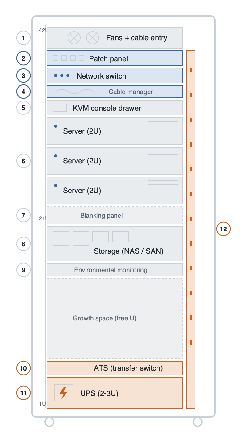
42U rack cabinet front view with numbered components
A typical 42U rack, seen from the front. The layout logic is always the same: light networking gear on top, servers and storage in the middle, and heavy power equipment at the very bottom.

The placement is not random. Hot air rises, so cooling and cable entry sit at the top; the heaviest items (batteries) go to the bottom so the cabinet cannot tip. Reading the rack from top to bottom:

# Component Typical size / place What it does
1 Fans + cable entry Top Fans exhaust the hot air that rises off the equipment; cables enter the cabinet here.
2 Patch panel 1U The tidy row of ports where dozens of incoming network cables terminate — like a fuse box, but for data. Cables land here first so a single change does not mean unplugging everything.
3 Network switch 1U The cabinet’s post office: it connects every server to the others and to the internet, and decides which data goes where. Placed just below the patch panel to keep the links short.
4 Cable manager 1U The “comb” that combs and lays down the cable clutter. Good cable order is often what separates a well-built cabinet from a bad one — messy cabling blocks airflow and makes fault-finding a nightmare.
5 KVM console drawer 1U A pull-out drawer with a fold-away screen and keyboard (KVM = Keyboard, Video, Mouse). One technician can reach every server without a separate monitor per machine.
6 Servers 1U / 2U The real tenants — the computers that do the work (websites, databases, camera recording). Flat “pizza-box” units that slide out on rails; front LEDs show run/fault status.
7 Blanking panels Filler Flat covers over unused slots. Not decoration: cold air is drawn in at the front and hot air pushed out the back, and open gaps let hot air short-circuit back to the front. Blanking panels stop that.
8 Storage (NAS / SAN) 2U – 4U The archive room: a unit holding dozens of disks where the data actually lives. Servers do the computing; storage keeps the data. Faulty disks are hot-swapped without shutting the system down.
9 Environmental monitoring 1U / 0U The cabinet’s thermometer and alarm: it watches temperature, humidity, door opening and water leaks, and messages the operator when something is wrong.
10 ATS — automatic transfer switch 1U An automatic switch that changes between two power sources within seconds. If the mains fails, the ATS transfers to the second source (generator or second feed) by itself — nobody swaps plugs by hand.
11 UPS — uninterruptible power supply 2U – 3U, bottom A battery-backed unit that takes over the instant power is lost and keeps the cabinet alive until the generator starts or the system shuts down cleanly. Batteries are heavy, so the UPS always sits at the bottom.
12 PDU — power distribution unit 0U, vertical at the rear The cabinet’s intelligent power strip: it takes power from the UPS and distributes it to every device. Smart models meter each outlet and can be switched remotely. Mounted vertically at the rear so it uses no U-space.

How power travels through the cabinet

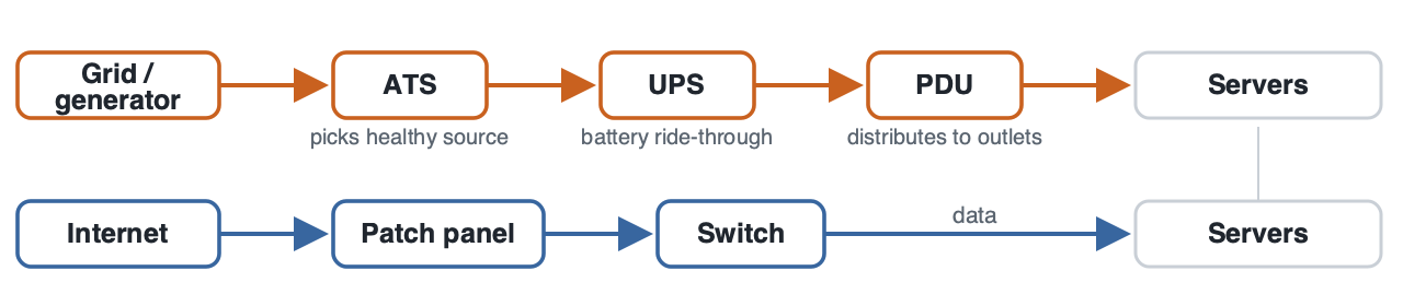
Power chain and data chain in a rack cabinet
Two separate veins run through the cabinet. The orange power chain conditions and distributes electricity; the blue data chain carries the internet to the servers. Most of the products you specify — UPS, ATS, PDU — are links in the orange chain.

Electrical continuity is the whole point of a well-designed cabinet. Utility power (and, where present, a generator) feeds the ATS, which always selects the healthy source. From there the supply passes through the UPS, which rides through short interruptions on battery, and then to the PDU, which distributes conditioned power to every device. This is exactly the kind of resilient distribution and medium-voltage switchgear thinking used upstream in substations — only scaled down to a single cabinet. The same discipline of source selection, backup and protection applies whether the equipment is a rack ATS or a feeder protection relay.

Details worth knowing

  • The doors are perforated. Front and rear doors are honeycomb-perforated so cold air enters at the front and hot air leaves at the back. Elegant glass doors are a poor choice for a server cabinet — they trap heat.
  • Heavy at the bottom. UPS and batteries go lowest, light networking gear on top. Cabinets sit on castors or adjustable feet and, in seismic regions, are bolted to the floor.
  • Two of everything. In serious installations the power chain is doubled: two PDUs, dual power supplies in the servers, two independent feeds. The goal is that a single failed part never stops the system — which is why PDUs and UPS units are usually sold in pairs.
  • Grounding and labelling. The metal body is earthed, and in a proper build every cable is labelled at both ends. The fastest way to judge a cabinet’s quality is to open the rear door and look at the cabling.

Frequently asked questions

What does “U” mean in a rack cabinet?
U stands for “rack unit” and equals 4.45 cm of vertical space. A 42U cabinet has 42 of these mounting positions, so a 2U server occupies two of them.

Why is the UPS always at the bottom of the rack?
UPS units contain heavy batteries. Placing the heaviest item at the bottom keeps the cabinet’s centre of gravity low so it cannot tip, especially when servers are slid out on their rails.

What is the difference between an ATS and a UPS?
An ATS switches between two power sources (for example mains and generator) within seconds, while a UPS bridges the gap on battery during the switch-over and conditions the supply. They work together: the ATS chooses the source, the UPS covers the moment of transfer.

What is the difference between a PDU and a normal power strip?
A basic PDU resembles a multi-outlet extension lead, but managed PDUs meter the current on each outlet, report it remotely and can switch individual outlets on or off — essential for monitoring load and cycling equipment without a site visit.

Why are blanking panels important?
They close unused slots so hot exhaust air cannot loop back to the cold intake. Without them, cooling efficiency drops and equipment runs hotter than it should.

Are rack cabinets a standard size?
The 19-inch mounting width is a global standard, which is why equipment from any manufacturer fits any cabinet. Height varies, with 42U being the most common, and depth is chosen to suit the equipment.


Looking for medium voltage switchgear and power distribution equipment?
Looking for high-quality medium voltage switchgear and power distribution equipment? We provide expert engineering support and reliable products for all your medium voltage needs.
For quotations and requests: info@electricistanbul.com
WhatsApp: +90 501 076 69 91
Neutral Grounding Resistor (NGR) Sizing and Se

Neutral Grounding Resistor (NGR) Sizing and Selection: A Step-by-Step Calculation Guide

A neutral grounding resistor (NGR) is a resistive impedance connected between a power system’s neutral point and earth, engineered to limit single-line-to-ground fault current to a controlled, predetermined magnitude while still allowing protective relays to detect the fault. Sizing an NGR correctly is one of the most consequential decisions in medium-voltage (MV) system design: too low a resistance value lets fault current climb toward damaging levels, while too high a value can make ground faults invisible to standard overcurrent protection. This guide walks through the governing formulas, a fully worked numerical example, a comparative selection table, and the practical pitfalls engineers encounter when specifying an NGR for transformers, generators, or switchgear neutral points. It is written for procurement engineers and design teams sourcing equipment for grids across the Middle East and Gulf (including Egypt and Saudi Arabia), North Africa, the CIS region, and Sub-Saharan Africa, where resistance-grounded MV distribution is the dominant practice for industrial and utility networks.

For related equipment context, see our hub pages on [medium-voltage switchgear](https://powersolutionshub.com/what-is-mv-switchgear-medium-voltage-switchgear/) and [protection relays](https://powersolutionshub.com/what-is-a-medium-voltage-protection-relay-mv-protection-relay/), and our transformer technical resources.

Neutral Grounding Resistor (NGR) Sizing and Se — schematic
Neutral Grounding Resistor (NGR) Sizing and Se — schematic.

The Method: Core NGR Sizing Formulas

NGR sizing starts from the system’s line-to-neutral (phase) voltage and the target ground-fault current the designer wants to permit. The fundamental relationship is Ohm’s law applied at the neutral point:

R = V_LN / I_G

Where: – R = required neutral grounding resistance (ohms) – V_LN = system line-to-neutral voltage = V_LL / √3 (volts) – I_G = desired maximum single-line-to-ground fault current (amperes)

The resistor’s continuous or short-time power rating is then derived from:

P = I_G² × R (for the resistor’s thermal duty), typically expressed as a kW rating for a specified time duration (e.g., 10 seconds or 1 minute), since NGRs are usually rated for short-time duty rather than continuous duty.

A second, equally important formula checks the resistor against the system’s zero-sequence charging capacitance, because the whole point of resistance grounding is to make the resistive fault current dominate over the capacitive charging current:

I_R ≥ I_C (approximately), where I_C is the total per-phase capacitive charging current of the network (cables, windings, surge capacitors). Low-resistance grounding schemes typically target I_R several times larger than I_C to ensure effective, low-transient-overvoltage fault clearing, while high-resistance grounding schemes deliberately size I_R close to or just above I_C to limit fault current to only a few amperes for continued (non-tripping) operation on the first ground fault.

Finally, the resistor must be checked against the transient recovery voltage and the arc-flash energy that protection settings will allow — this is a coordination step performed together with the protection relay engineer, not a standalone calculation.

Selection reference
Selection reference.

Worked Example: Sizing an NGR for an 11 kV Transformer Neutral

Step 1 — Establish system parameters. Assume a distribution transformer feeds an 11 kV system and the design target is to limit ground-fault current to a low-resistance grounding value of 400 A (a common utility target for feeder protection coordination).

Line-to-neutral voltage: V_LN = V_LL / √3 = 11,000 / 1.732 ≈ 6,351 V

Step 2 — Calculate required resistance. R = V_LN / I_G = 6,351 / 400 ≈ 15.9 Ω

Step 3 — Calculate the resistor’s thermal (power) rating. For a short-time rating of, say, 10 seconds: P = I_G² × R = (400)² × 15.9 ≈ 2,544,000 W ≈ 2,544 kW for 10 seconds

Because this is a short-time duty, the resistor element is designed to absorb this energy thermally over the rated time and then cool — it is not a continuous 2,544 kW load. The design engineer specifies the resistor’s time-current withstand curve so it survives the maximum expected fault duration set by the upstream protection (including breaker failure backup time), with margin.

Step 4 — Cross-check against high-resistance grounding, for comparison. If instead the design goal were high-resistance grounding to hold ground-fault current to a much smaller value — for example 25 A, chosen to exceed the system’s estimated charging current I_C and allow alarm-only operation on the first fault:

R = V_LN / I_G = 6,351 / 25 ≈ 254 Ω

P = I_G² × R = (25)² × 254 ≈ 158,750 W ≈ 159 kW

This comparison shows how dramatically the required resistance and let-through current change depending on whether the grounding philosophy is low-resistance (fast trip on first fault, larger resistor current, lower ohmic value) or high-resistance (alarm on first fault, tiny resistor current, much higher ohmic value).

Step 5 — Verify protection coordination. The ground-fault relay’s pickup setting must sit comfortably below I_G (400 A in the low-resistance case) with margin for CT accuracy and downstream fault contribution, while remaining above normal system unbalance and CT/CBCT error currents. This step is typically performed jointly with the protection relay engineer using the specific relay’s ground-fault element characteristics.

Selection & Comparison Table

Parameter Low-Resistance Grounding (LRG) High-Resistance Grounding (HRG)
Typical ground-fault current target Tens to hundreds of amperes A few amperes, just above I_C
Trip philosophy Immediate/fast trip on first fault Alarm on first fault; locate and clear before second fault
Resistor ohmic value Lower (tens of ohms, per worked example ≈16 Ω) Higher (hundreds of ohms, per worked example ≈254 Ω)
Typical duty rating Short-time (e.g., 10 s or similar) Short-time or continuous, depending on scheme
Common application Distribution feeders, industrial plants needing fast fault clearing Continuous-process industries (petrochemical, generation) needing ride-through
Overvoltage transient control Good, resistive current suppresses transient overvoltages Good, provided I_R ≥ I_C is satisfied
Typical relay approach Standard ground overcurrent (51N/50N) Sensitive ground-fault detection with alarm, often pulsing schemes for fault location

Selection Criteria and Common Pitfalls

1. Match the resistor to the protection philosophy, not just the transformer size. The kVA rating of the connected transformer determines available fault current capability, but the actual I_G target is a protection-coordination decision made jointly with the relay engineer — sizing the NGR in isolation is the most common design error.

2. Confirm the time rating, not just the ohmic value. A resistor sized correctly in ohms but under-rated in short-time thermal withstand will fail during a sustained or repeated fault, especially where breaker failure or backup clearing times are long.

3. Check I_R versus I_C for high-resistance schemes. If the resistor’s rated current is not adequately above the system’s total charging current, transient overvoltages during arcing ground faults can exceed equipment insulation withstand — defeating the purpose of resistance grounding.

4. Verify voltage rating and BIL match the connected system. The NGR’s insulation must be rated for the full line-to-neutral voltage plus a margin, since during a ground fault the resistor briefly sees near-full phase voltage across it.

5. Coordinate with generator neutral grounding practices separately. Generators often use different grounding philosophies (frequently higher-resistance, lower let-through current) than distribution transformers, because generator windings are more sensitive to fault-induced iron damage; a single sizing rule should not be applied uniformly across generator and transformer neutrals on the same system without review.

6. Account for multiple grounding points. On systems with more than one transformer or generator neutral, only one NGR (or one grounding path) should normally be active at a time to avoid unintended parallel paths that change the effective fault current — this is managed through neutral grounding switchgear and interlocking schemes.

7. Environmental and duty-cycle derating. Ambient temperature, altitude, and enclosure ventilation affect the resistor’s thermal withstand and must be checked against the manufacturer’s correction factors for the specific installation site.

Standards Reference

NGR application and sizing practice is guided primarily by IEEE Std 32 (IEEE Standard for Requirements, Terminology, and Test Procedures for Neutral Grounding Devices), which defines resistor rating conventions, time-current withstand testing, and terminology for neutral grounding resistors and reactors. System grounding philosophy and its effect on protection coordination is further addressed in IEEE Std 142 (the “Green Book” on grounding of industrial and commercial power systems). Where MV switchgear housing the grounding resistor or neutral grounding cubicle is involved, the switchgear itself is covered by the relevant IEC 62271 series switchgear standards, but the resistor element’s own rating and test methodology follows the IEEE 32 framework referenced above. Designers working in IEC-based jurisdictions typically apply these same first-principles calculations, since resistance-grounding sizing methodology is standard practice rather than a code-mandated single value.

Related guides

See also our guides on gas-insulated switchgear, ring main units and metal-clad switchgear.

What is the difference between low-resistance and high-resistance neutral grounding?

Low-resistance grounding (LRG) targets tens to hundreds of amperes of ground-fault current to allow fast, selective tripping, while high-resistance grounding (HRG) limits fault current to only a few amperes above the system’s charging current so operation can continue with an alarm until the fault is located and cleared.

How do I choose the target ground-fault current for an NGR?

The target is a joint decision with the protection engineer, based on relay sensitivity, CT ratios, acceptable equipment damage during a fault, and whether the operating philosophy calls for immediate tripping or alarm-first operation.

Why is the NGR power rating expressed as a short-time rating instead of continuous?

Because ground faults are expected to be cleared quickly by protection, the resistor only needs to absorb the calculated fault energy for the maximum expected clearing time (including backup protection margin), so manufacturers rate the element thermally for a defined short duration rather than continuous full-current duty.

What happens if the NGR resistance value is too high?

If resistance is too high, the resulting ground-fault current may fall below the ground-fault relay’s minimum reliable pickup setting, causing faults to go undetected — a serious protection coordination failure.

What happens if the NGR resistance value is too low?

Too low a resistance allows the ground-fault current to approach solidly-grounded system magnitudes, increasing arc-flash energy, equipment damage, and step/touch-potential hazards at the fault location.

Does every transformer or generator neutral need its own NGR?

Not necessarily — on systems with multiple potential grounding points, engineers typically activate only one grounding path at a time, using interlocked neutral grounding switchgear, to avoid unintended parallel current paths that would change the effective fault current seen by protection.

Which standard should I reference for NGR ratings and testing?

IEEE Std 32 is the primary reference for neutral grounding resistor and reactor ratings, terminology, and test procedures, complemented by IEEE Std 142 for overall system grounding philosophy.

Looking for neutral grounding resistors?

Looking for high-quality neutral grounding resistors? We provide expert engineering support and reliable products for all your medium voltage needs.

For quotations and requests: info@electricistanbul.com

WhatsApp: +90 501 076 69 91
Transformer Sizing Calculation

Transformer Sizing Calculation: How to Select the Right kVA Rating

Transformer sizing calculation is the engineering process of determining the correct apparent-power (kVA) rating of a power or distribution transformer so that it can supply the connected electrical load continuously, safely, and with adequate margin for growth, without exceeding its thermal and voltage-regulation limits. This guide walks through the first-principles method used by MV distribution engineers — load assessment, demand and diversity factors, the core sizing formula, a fully worked kVA example, a comparison table of typical sizing steps, and the IEC/IEEE references that govern transformer ratings and testing. It also flags the selection pitfalls that most often lead to oversized or undersized transformers on real projects. This methodology applies equally to industrial plants, utility substations, and infrastructure projects across the Middle East and Gulf region (including Egypt and Saudi Arabia), North Africa, the CIS, and Sub-Saharan Africa, where correct kVA selection directly affects capital cost, losses, and long-term reliability.

Proper sizing sits upstream of every other MV design decision: it determines the current your switchgear must interrupt, the settings your [protection relays](https://powersolutionshub.com/what-is-a-medium-voltage-protection-relay-mv-protection-relay/) must be coordinated to, and the winding configuration your medium voltage transformer must be built with. Getting the kVA figure wrong cascades into every downstream component.

Transformer Sizing Calculation — schematic
Transformer Sizing Calculation — schematic.

Why Transformer Sizing Matters

An undersized transformer runs continuously near or above its nameplate rating, accelerating insulation ageing, increasing losses, and risking premature failure during peak demand or motor-starting inrush. An oversized transformer, by contrast, wastes capital, occupies unnecessary substation footprint, operates inefficiently at very light load (poor part-load efficiency and higher no-load loss as a fraction of throughput), and can complicate protection coordination because fault current levels and relay pickup settings must be re-verified. Correct sizing is therefore a balance between:

  • present connected load and realistic diversity/demand factors,
  • planned future load growth over the transformer’s service life,
  • voltage regulation and permissible tap range,
  • ambient temperature, altitude, and cooling class derating,
  • fault-current withstand and coordination with upstream/downstream protection.
Selection reference
Selection reference.

The Sizing Method / Core Formula

Step 1 — Establish the connected load (kW). Sum the rated power of every load (motors, lighting, HVAC, process equipment) that will be served from the transformer’s secondary.

Step 2 — Apply demand and diversity factors. Not all connected loads operate simultaneously at full rating. Multiply the connected load by a demand factor (fraction of connected load expected to operate) and, for multiple feeders, a diversity factor (accounting for non-coincident peaks) to obtain the maximum demand (kW).

Step 3 — Convert to apparent power using the load power factor.

S (kVA) = P (kW) / cos φ

where P is the maximum demand in kW and cos φ is the aggregate load power factor.

Step 4 — Add a growth/safety margin. Engineers typically size the transformer above the calculated demand to allow for load growth over the asset’s operating life and to avoid running continuously at 100% loading. This margin is a project-specific engineering decision, not a fixed universal number, and should reflect the site’s expansion plans.

Step 5 — Select the nearest standard kVA rating from the manufacturer’s standard range that meets or exceeds the margined demand, then verify voltage regulation, cooling class, and fault-withstand requirements against that rating.

Step 6 — Derive the rated full-load current for downstream cable, switchgear, and protection sizing:

For a three-phase transformer:

I (A) = S (kVA) × 1000 / (√3 × V (V))

This full-load current is the reference value used to size secondary cables, select CT ratios, and set overload/thermal protection relays.

Worked Example: Sizing a Transformer for an Industrial Feeder

Scenario: A facility has a connected load of 900 kW across motors, lighting, and auxiliary equipment. The plant’s demand factor is 0.85 (not everything runs simultaneously), and the aggregate load power factor is 0.9 lagging. The utility supplies at 11 kV, and the plant wants a 20% margin for future expansion.

Step 1 — Maximum demand (kW): Maximum demand = Connected load × Demand factor = 900 kW × 0.85 = 765 kW

Step 2 — Convert to apparent power (kVA): S = P / cos φ = 765 / 0.9 ≈ 850 kVA

Step 3 — Apply the growth margin: S(with margin) = 850 kVA × 1.20 = 1,020 kVA

Step 4 — Select the nearest standard rating: The nearest standard transformer rating above 1,020 kVA is commonly 1000/1250 kVA depending on the manufacturer’s standard series; here we select 1250 kVA to keep headroom above the margined demand.

Step 5 — Calculate the rated full-load secondary current (assume secondary voltage 415 V, three-phase):

I = S / (√3 × V) = 1,250,000 / (1.732 × 415) ≈ 1,739 A

Step 6 — Calculate the primary-side current at 11 kV for reference (useful for MV switchgear and protection sizing):

I = S / (√3 × V) = 1,250,000 / (1.732 × 11,000) ≈ 65.6 A

This primary current figure — in this illustrative example, roughly 65.6 A — is the value the upstream MV switchgear and protection relay settings would be coordinated around, together with the transformer’s impedance for through-fault calculations.

Note: all figures above (765 kW, 850 kVA, 1,020 kVA, 1250 kVA, ~1,739 A, ~65.6 A) are illustrative computed results of this worked example using assumed inputs, not manufacturer specification values.

Sizing Steps at a Glance

Step Action Formula / Basis Example Result
1 Determine connected load Sum of nameplate loads 900 kW
2 Apply demand factor Connected load × demand factor 765 kW
3 Convert to kVA P / cos φ ≈ 850 kVA
4 Apply growth margin S × (1 + margin %) ≈ 1,020 kVA
5 Round to standard rating Nearest catalog kVA 1250 kVA
6 Compute full-load current I = S / (√3 × V) ≈ 65.6 A at 11 kV / ≈ 1,739 A at 415 V

Selection Criteria and Common Pitfalls

Voltage regulation. Confirm that at the calculated load current, the voltage drop across the transformer’s impedance stays within the acceptable band at the secondary busbar, especially where long cable runs add further drop.

Cooling class and ambient derating. A transformer’s kVA rating is defined for a specific cooling method and ambient temperature/altitude. Sites with high ambient temperature or altitude above the reference conditions may require a derated (larger) unit — always check the manufacturer’s correction factors rather than assuming the nameplate kVA applies unmodified.

Inrush and motor-starting duty. If large motors are started direct-on-line from the transformer, the sizing calculation must also check that starting current does not cause excessive voltage dip, which may push the required kVA above the value calculated from steady-state demand alone.

Short-circuit withstand and impedance. The transformer’s impedance value affects both voltage regulation and the fault current seen by downstream protection; it must be selected jointly with the switchgear’s rated short-circuit breaking current and the relay’s fault settings.

Avoid the “round up twice” trap. Applying a demand factor, a diversity factor, a growth margin, and then rounding up to the next standard size independently at every step compounds conservatism and can result in a transformer two sizes larger than necessary. Apply margins once, in a documented and traceable way.

Avoid undersizing from connected-load misuse. Conversely, sizing directly from raw connected load without applying realistic demand and diversity factors leads to an oversized estimate that a hasty “cost-cutting” review may then wrongly shrink — always keep the demand-factor step explicit and justified.

Future expansion. Substation civil works and switchgear bus ratings are far more expensive to upgrade later than to provision for at the design stage; the growth margin decision should be made jointly with facilities/planning teams, not left to a rule of thumb.

Standards and References

Transformer rating, temperature rise, and testing requirements are governed by the IEC 60076 series (Power Transformers), which defines rated power, temperature-rise limits, tapping, and test procedures for oil-immersed and dry-type units. Loading guidance for transformers, including guidance on loading above nameplate rating under defined conditions, is addressed in IEC 60076-7 (Loading guide for oil-immersed power transformers) and the equivalent IEC 60076-12 for dry-type transformers. On the IEEE side, IEEE C57.91 provides loading guidance for oil-immersed transformers used widely in North American and IEEE-aligned markets. Protection coordination for the transformer and its associated switchgear should reference the applicable IEC 62271 series for the switchgear class involved, while cable and current-carrying capacity should follow the relevant IEC cable ampacity standards. Always confirm the exact edition and part applicable to the specific transformer type (oil-immersed vs. dry-type/cast resin) and cooling class before finalizing a design.

Related guides

See also our guides on medium voltage switchgear, gas-insulated switchgear and ring main units.

What is the basic formula for transformer sizing calculation?

The core formula converts real power demand to apparent power: S (kVA) = P (kW) / cos φ, where P is the maximum demand after applying demand and diversity factors, and cos φ is the aggregate load power factor. A growth margin is then added before rounding to the nearest standard kVA rating.

How do I calculate the full-load current of a transformer once I know its kVA rating?

Use I (A) = S (kVA) × 1000 / (√3 × V), with V as the line-to-line voltage in volts for a three-phase system. This current is used to size cables, CTs, and protection relay settings on both primary and secondary sides.

Why should I add a margin above the calculated demand?

A margin accounts for future load growth, avoids continuous operation at 100% nameplate loading (which accelerates insulation ageing), and provides headroom for motor-starting or seasonal peak conditions. The exact percentage is a project-specific engineering decision.

Does ambient temperature or altitude affect the required kVA rating?

Yes. Transformer nameplate ratings are defined for specific reference ambient and altitude conditions in IEC 60076. Sites operating outside those reference conditions typically require a derating factor applied to the load, which may push the design toward a larger standard kVA size.

What is the difference between demand factor and diversity factor in sizing calculations?

Demand factor reduces a single load group’s connected kW to reflect that not all equipment runs simultaneously at full rating. Diversity factor is applied across multiple load groups or feeders to reflect that their individual peaks do not occur at the same time; it typically further reduces the combined maximum demand.

Which IEC standard governs transformer ratings and loading?

The IEC 60076 series defines general requirements, ratings, and testing for power transformers, with IEC 60076-7 (oil-immersed) and IEC 60076-12 (dry-type) providing specific loading guidance. IEEE C57.91 is the equivalent loading guide used in IEEE-aligned markets.

Can I use this same method for dry-type (cast resin) transformers?

The core kVA and current formulas are identical regardless of transformer construction. However, cooling class, temperature-rise limits, and loading guidance differ between oil-immersed and dry-type/cast resin transformers, so the applicable IEC 60076 part and manufacturer derating tables must match the actual transformer type selected.

Looking for medium voltage transformers?

Looking for high-quality medium voltage transformers? We provide expert engineering support and reliable products for all your medium voltage needs.

For quotations and requests: info@electricistanbul.com

WhatsApp: +90 501 076 69 91
Short-Circuit Current Calculation (MV)

Short-Circuit Current Calculation (MV): A Worked Example

Short-circuit current calculation is the engineering process of determining the magnitude of fault current — initial symmetrical (Ik″), peak (ip), and thermal equivalent (Ith) — that flows in a medium-voltage network when a three-phase, phase-to-phase, or phase-to-earth fault occurs, so that switchgear, cables, busbars, and protection relays can be correctly rated and coordinated. This guide walks through the governing method, a fully worked numerical example from grid to busbar, a comparison table for equipment selection, common pitfalls, and the applicable IEC/IEEE standards. The approach applies equally to utility substations and industrial MV switchrooms across the Middle East and Gulf region (including Egypt and Saudi Arabia), North Africa, the CIS, and Sub-Saharan Africa, where grid strength and transformer sizing vary widely from site to site.

Short-Circuit Current Calculation (MV) — schematic
Short-Circuit Current Calculation (MV) — schematic.

Why short-circuit calculation matters

Every piece of MV equipment — switchgear, [medium voltage switchgear](https://powersolutionshub.com/what-is-mv-switchgear-medium-voltage-switchgear/) busbars, cable sizing, current transformers, and medium voltage protection relays — is only safe and selective if it is rated above the maximum fault current the network can actually deliver at that point. Undersizing leads to catastrophic failure (arcing faults, busbar burn-through); oversizing wastes capital. The calculation also feeds directly into protection relay settings: instantaneous and time-delayed overcurrent thresholds are set as a function of Ik″ at each protection zone, and correct discrimination between upstream and downstream relays depends on knowing how fault current changes along the network.

Selection reference
Selection reference.

The method / formula (IEC 60909 approach)

The internationally recognised method for calculating three-phase short-circuit currents is defined in IEC 60909-0, “Short-circuit currents in three-phase AC systems — Calculation of currents.” The IEEE equivalent guidance is found in IEEE Std 551 (the “Violet Book”) and ANSI/IEEE C37.010, used mainly in North American practice for symmetrical-current-rated breakers.

The core steps are:

1. Rated (load) current — establishes normal operating current, used as a sanity check: I = S / (√3 × Un)

2. Source/grid impedance, derived from the known short-circuit power (Sk″) at the point of connection: Zs = c × Un² / Sk″

3. Transformer impedance, from its rated impedance voltage (uk%): Zt = (uk% / 100) × (Un² / Sn)

4. Total impedance to the fault point: Ztotal = ΣZ (source + transformer + cable/line impedances, added as complex R+jX)

5. Initial symmetrical short-circuit current: Ik″ = c × Un / (√3 × Ztotal)

6. Peak short-circuit current (accounts for the DC offset in the first half-cycle): ip = κ × √2 × Ik″

7. Thermal equivalent short-time current (Ith), used to check thermal withstand of cables and busbars over the protection clearance time.

The factor c is the IEC 60909 voltage factor (typically 1.1 for maximum-current calculations in MV networks, and a lower value for minimum-current studies used in relay sensitivity checks). The factor κ depends on the network’s X/R ratio and is read from IEC 60909 curves or approximated for hand calculations.

Worked example

Assume the following simplified radial network, from utility connection down to an 11 kV industrial switchboard:

  • Utility grid short-circuit power at the 33 kV point of connection: Sk″ = 500 MVA
  • Step-down transformer: 33/11 kV, 10 MVA, impedance voltage uk = 8%
  • Voltage factor per IEC 60909: c = 1.1
  • Assume reactance dominates (X ≈ Z) for a first-pass hand calculation — a simplification acceptable for MV networks with high X/R ratios; a full study should keep R and X separate.

Step 1 — Source impedance, referred to the 11 kV side: Zs = c × Un² / Sk″ = 1.1 × (11,000 V)² / 500,000,000 VA Zs = 1.1 × 121,000,000 / 500,000,000 ≈ 0.266 Ω

Step 2 — Transformer impedance, referred to the 11 kV secondary: Zt = (uk / 100) × (Un² / Sn) = 0.08 × (121,000,000 / 10,000,000) Zt = 0.08 × 12.1 ≈ 0.968 Ω

Step 3 — Total impedance to the 11 kV busbar: Ztotal = Zs + Zt = 0.266 + 0.968 ≈ 1.234 Ω

Step 4 — Initial symmetrical short-circuit current at the 11 kV busbar: Ik″ = c × Un / (√3 × Ztotal) = (1.1 × 11,000) / (1.732 × 1.234) Ik″ = 12,100 / 2.137 ≈ 5,662 A ≈ 5.66 kA

Step 5 — Peak short-circuit current (assume κ = 1.8, a typical value for a transformer-dominated MV feeder with moderate X/R): ip = κ × √2 × Ik″ = 1.8 × 1.414 × 5,662 ≈ 14,410 A ≈ 14.4 kA

Step 6 — Thermal equivalent short-time current (simplified, ignoring DC decay factors m and n, over a 1-second protection clearance time): Ith ≈ Ik″ ≈ 5.66 kA for 1 s

This tells the design engineer that the 11 kV switchboard, its busbars, and the incoming feeder cable must be rated for an initial symmetrical fault current of at least ~5.7 kA, a peak (making) current of at least ~14.4 kA, and a 1-second thermal withstand of at least ~5.7 kA. The result also becomes the basis for setting the instantaneous pickup of the incoming medium voltage protection relay, which should be set below the calculated Ik″ with margin, but above maximum load and inrush currents.

Fault-level progression and equipment selection table

Network point Impedance to point (Ω) Ik″ (initial symmetrical) Peak ip (κ=1.8) Relevance
33 kV grid connection Zs ≈ 0.266 (ref. 11 kV) ~24.9 kA (at 33 kV side, illustrative) Utility infeed strength
11 kV transformer secondary / MV busbar Ztotal ≈ 1.234 ≈ 5.66 kA ≈ 14.4 kA Governs switchgear breaking/making rating
Downstream 11 kV feeder (after cable impedance added) Ztotal + Zcable (higher) Lower than 5.66 kA Lower than 14.4 kA Governs feeder relay grading and cable thermal check

The table illustrates the general first-principles rule: fault current is highest closest to the source and decreases as impedance (transformer + cable) is added downstream. This progression is exactly what protection engineers use to grade relay time-current curves for selectivity.

Selection criteria and common pitfalls

When using the calculated Ik″, ip, and Ith to select or verify equipment, check the following:

  • Rated short-circuit breaking current of the switchgear must be ≥ calculated Ik″ at that busbar, with margin for future network growth.
  • Rated peak withstand (making) current must be ≥ calculated ip — this is the mechanical stress the switchgear and busbar must survive during the first cycle.
  • Rated short-time withstand current and duration must cover the calculated Ith for the actual protection clearance time (commonly 1 s or 3 s in specifications), not just the instantaneous value.
  • Motor contribution: rotating machines (motors, generators) connected to the busbar add their own fault-current contribution during the first cycles and must be included in industrial plant calculations — omitting it is a frequent source of under-rated switchgear.
  • X/R ratio accuracy: using a generic κ value without checking the actual X/R ratio of the network can under- or over-estimate the peak current significantly; transformer-dominated MV networks typically have higher X/R (higher κ) than cable-dominated LV networks.
  • Minimum vs maximum fault current: use c-factor for maximum current (breaker sizing) and the corresponding lower c-factor for minimum current studies (relay sensitivity and reach checks) — using only the maximum case can leave remote-end faults undetected by protection.
  • Meshed vs radial topology: parallel transformers or ring-fed networks require impedance combination (parallel Z) rather than simple series addition, and often need computer-based short-circuit software rather than hand calculation.
  • Data source impedance: an inaccurate utility Sk″ figure (often just an assumption at design stage) is one of the most common root causes of later fault-level disputes — always confirm with the utility before finalising switchgear and transformer impedance selection.

Standards

The primary reference for MV three-phase short-circuit calculations is IEC 60909-0, “Short-circuit currents in three-phase AC systems — Calculation of currents,” which defines the voltage factor c, the peak factor κ, and the thermal equivalent current methodology used throughout this guide. In IEEE-based practice, IEEE Std 551 (Violet Book) and ANSI/IEEE C37.010 provide the equivalent framework for symmetrical- and asymmetrical-current-rated circuit breakers. Protection relay coordination studies built on these fault levels typically reference IEC 60255 for relay performance and IEC 61850 where digital substation communication is involved.

Related guides

See also our guides on gas-insulated switchgear, ring main units and metal-clad switchgear.

What is the difference between Ik″, ip, and Ith?

Ik″ is the initial symmetrical RMS short-circuit current at the instant of fault, ip is the peak (asymmetrical) current reached within the first half-cycle including the DC offset, and Ith is the thermal equivalent RMS current used to check the withstand capability of cables, busbars, and switchgear over the fault clearance time.

Why does the voltage factor c matter?

The IEC 60909 factor c accounts for voltage variations, transformer tap positions, and subtransient behaviour of sources; using c=1.1 for maximum-current studies ensures switchgear is rated for the worst realistic fault current, while a lower c is used for minimum-current relay sensitivity checks.

Do I need to include motor contribution in every MV short-circuit study?

Yes, in industrial plants with significant motor load. Induction and synchronous motors feed additional fault current into a nearby short circuit for the first several cycles, and this contribution can materially increase both Ik″ and ip at the switchboard.

How does short-circuit current calculation affect protection relay settings?

The calculated Ik″ at each protection zone defines the range within which instantaneous and time-delayed overcurrent elements of the [protection relay](/medium-voltage-protection-relays) must be set — high enough to avoid nuisance tripping on load/inrush, but low enough to guarantee fast clearance of an actual fault, while maintaining discrimination with adjacent relays.

Can I use a simplified reactance-only calculation instead of full R+jX?

For quick hand calculations on transformer-dominated MV networks with high X/R ratios, a reactance-only approximation is common and reasonably accurate; however, for cable-dominated or low-voltage-adjacent networks, resistance becomes significant and should not be ignored in a detailed study.

What happens if switchgear is under-rated for the calculated fault current?

Equipment rated below the actual Ik″/ip/Ith at its installation point risks catastrophic failure during a real fault — including internal arcing, busbar deformation, or explosive rupture — which is why fault-level verification is mandatory before finalising [switchgear](/medium-voltage-switchgear) and cable specifications on any project.

How does adding a second parallel transformer change the calculation?

Parallel transformers reduce the total source impedance seen at the shared busbar (impedances combine as parallel elements), which increases the fault current at that busbar compared with a single-transformer feed — this is a common reason fault levels rise after plant expansions and require re-verification of existing switchgear.

Looking for medium voltage protection relays?

Looking for high-quality medium voltage protection relays? We provide expert engineering support and reliable products for all your medium voltage needs.

For quotations and requests: info@electricistanbul.com

WhatsApp: +90 501 076 69 91
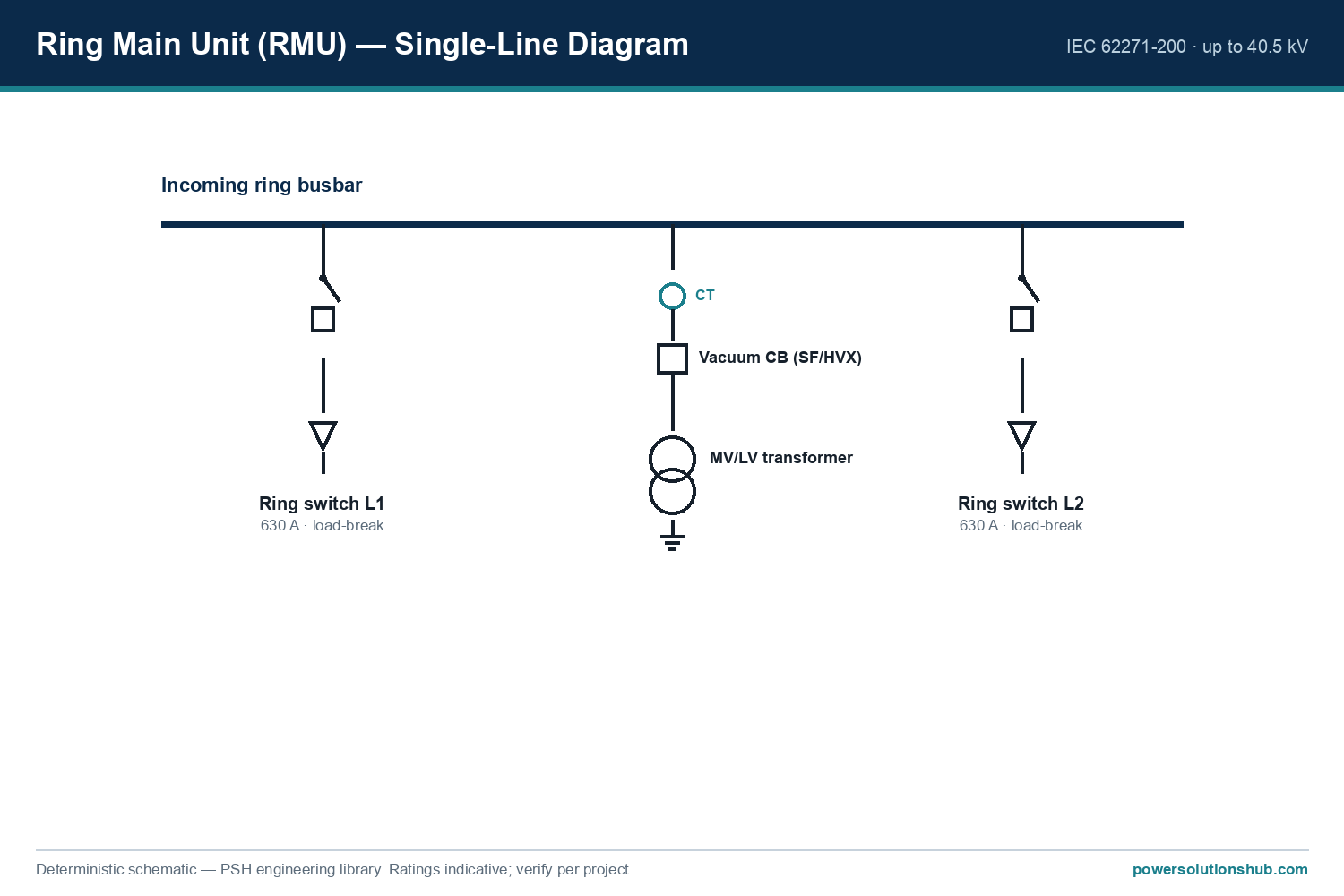
Current Transformer (CT) Sizing and Burden Cal

Current Transformer (CT) Sizing and Burden Calculation: A Step-by-Step Engineering Guide

A current transformer (CT) is an instrument transformer that reproduces primary system current as a proportionally scaled, safe secondary signal — typically 5 A or 1 A — for use by protection relays, meters, and measuring instruments. Correct CT sizing means selecting the right rated primary current, ratio, burden capability, and accuracy class so the connected relay or meter sees an undistorted, sufficiently accurate signal across the full operating range, from normal load current up to fault current. This guide walks through the underlying formulas, a fully worked numerical example, a comparison table of protection versus metering classes, and the common sizing pitfalls that cause nuisance tripping or missed operations in the field. The same principles apply whether the installation is a compact ring main unit, a large air-insulated switchgear lineup, or a substation retrofit project across the Middle East and Gulf (including Egypt and Saudi Arabia), North Africa, CIS, and Sub-Saharan Africa markets that Power Solutions Hub serves.

Current Transformer (CT) Sizing and Burden Cal — schematic
Current Transformer (CT) Sizing and Burden Cal — schematic.

Why CT Sizing Matters

An undersized or mis-specified CT can saturate during a fault, distorting the secondary waveform exactly when the protection relay most needs an accurate signal. An oversized CT, on the other hand, may deliver a secondary current too small relative to its rated burden to be measured accurately at normal load, degrading metering precision and revenue accuracy. Because CTs sit at the boundary between the primary power system and the secondary protection/metering system, every downstream relay setting, energy metering calculation, and fault-clearing decision depends on the CT delivering a faithful, linearly scaled current signal within its design limits.

Selection reference
Selection reference.

The Core Formulas

1. CT ratio. A CT is specified by its rated transformation ratio, expressed as primary current to secondary current, for example 400/5 A or 1000/1 A. The ratio should be selected so that the expected maximum continuous load current runs at roughly 60–100% of the CT’s rated primary current — running a CT permanently at a very low fraction of its rated primary current degrades accuracy at normal load.

2. Rated burden. Burden is the total impedance (in VA at rated secondary current, or in ohms) that the CT secondary circuit must drive — this includes relay/meter input impedance, terminal wiring resistance, and connector losses. The formula is:

Burden (VA) = I_sec² × Z_burden

where I_sec is the rated secondary current (A) and Z_burden is the total secondary loop impedance (Ω).

3. Accuracy Limit Factor (ALF) for protection CTs. ALF defines the multiple of rated primary current up to which the CT maintains its stated accuracy (composite error) before significant saturation occurs. A protection-class CT with ALF 10 and accuracy class 5P (per IEC 61869-2) is expected to remain within its stated composite error limit up to 10 times rated primary current.

4. Rated Equivalent Limiting Secondary EMF (Vk-type checks) and knee-point voltage are used for more detailed saturation studies (particularly with differential and unit protection schemes), but the ALF/burden method below is sufficient for the great majority of MV feeder and transformer protection sizing tasks.

5. Cable burden formula. For secondary wiring runs from the CT to the relay panel:

Z_cable = ρ × (2L) / A

where ρ is the resistivity of copper conductor, L is the one-way cable length (m), and A is the conductor cross-sectional area (mm²). The factor of 2 accounts for the go-and-return conductor loop.

Worked Example: Sizing a Protection CT for an 11 kV Feeder

Consider an 11 kV feeder supplying a load rated at 1000 kVA, protected by an overcurrent relay located 30 metres from the CT, wired with 2.5 mm² copper control cable.

Step 1 — Determine rated primary current of the load.

I = S / (√3 × V) = 1,000,000 / (1.732 × 11,000) ≈ 52.5 A

Step 2 — Select the CT primary rating. Applying the rule of keeping normal load between roughly 60–100% of CT rated primary current, a CT rated 75/5 A or 100/5 A would be reasonable candidates; for this example we select 100/5 A, giving a ratio of 20:1. At the calculated load of 52.5 A, the CT operates at about 52.5% of its rated primary current — a little low, so in a real design a 75/5 A CT (giving ~70% loading) might be preferred to improve metering-range accuracy. This illustrates why the “60–100% of rated primary current” guideline matters in practice.

Step 3 — Calculate secondary cable burden. Using copper resistivity ρ ≈ 0.0175 Ω·mm²/m:

Z_cable = 0.0175 × (2 × 30) / 2.5 = 0.0175 × 60 / 2.5 = 0.42 Ω

Step 4 — Add relay burden. Assume the connected overcurrent relay has an input burden of 0.1 VA at 5 A rated secondary current. Converting to impedance:

Z_relay = VA / I_sec² = 0.1 / 5² = 0.004 Ω

Step 5 — Total secondary loop burden.

Z_total = Z_cable + Z_relay ≈ 0.42 + 0.004 ≈ 0.424 Ω

Total VA burden at rated secondary current = I_sec² × Z_total = 5² × 0.424 ≈ 10.6 VA

Step 6 — Compare against CT rated burden. If the CT is rated for 15 VA at its accuracy class, the calculated 10.6 VA burden is comfortably within capability, leaving margin for connector losses and future load growth. Had the calculated burden exceeded the CT’s rated VA, the next step would be to either shorten the cable run, upsize the conductor cross-section (reducing Z_cable), or select a CT with a higher rated burden.

Step 7 — Check fault-current performance (ALF). For a feeder with an available three-phase fault current of, say, 12.5 kA on the primary side, and a CT of ratio 100/5 A with ALF 10, the CT is guaranteed accurate up to 10 × 100 A = 1000 A on the primary side before significant saturation — meaning for fault currents that translate to more than 1000 A referred to the primary, the CT may partially saturate above that limit. This is why protection engineers select ALF (and sometimes CT knee-point voltage) in coordination with the maximum fault current the relay must correctly measure, not just normal load current.

Comparison Table: Protection vs. Metering CT Classes

Parameter Metering CT (e.g., class 0.5 / 0.2S) Protection CT (e.g., class 5P / 10P)
Purpose Accurate billing/measurement at normal load Accurate response at high fault multiples
Accuracy at rated current High precision near 100% load Moderate precision near 100% load
Behavior at fault current Designed to saturate early (protects meters) Designed to stay linear up to ALF × rated current
Key parameter Accuracy class (e.g., 0.5, 0.2S) Accuracy Limit Factor (ALF) and accuracy class (5P, 10P)
Governing standard IEC 61869-2 IEC 61869-2
Typical burden sizing focus Minimise burden for precision Ensure burden allows full ALF performance

Selection Criteria and Common Pitfalls

Match CT ratio to actual load, not nameplate transformer rating alone. Sizing purely off a transformer’s full-load nameplate current without accounting for typical operating load can leave the CT under-loaded most of the time, hurting metering accuracy.

Always calculate total secondary burden, not just relay input impedance. Long cable runs, small conductor cross-sections, and multiple relay/meter taps on the same CT circuit all add resistance. It’s a frequent field error to specify a CT class based on the relay datasheet alone while ignoring 20–50 metres of control cable.

Do not share one CT core across both protection and precision metering unless it is explicitly a dual-class or dual-core CT. A single core optimized for measurement accuracy will typically saturate at a current level too low to support reliable protection, while a protection-optimized core lacks the precision needed for billing metering.

Verify polarity and phase relationships. Incorrect CT polarity wiring is one of the most common commissioning errors, and it causes differential and directional protection schemes to maloperate even when the ratio and burden calculations are correct.

Check knee-point voltage for differential schemes. For transformer differential or busbar differential protection, burden and saturation calculations typically require a knee-point voltage check per the relevant IEC/IEEE guidance, in addition to the basic ALF and burden method described above.

Coordinate CT sizing with the switchgear and relay selection early. CT accuracy class, ratio, and burden should be confirmed against the specific protection relay’s input burden and the switchgear compartment’s available CT mounting arrangement — see our switchgear and protection relay resources for related sizing considerations.

Standards

Current transformers for protection and metering applications are governed internationally by IEC 61869-2 (Instrument transformers – Additional requirements for current transformers), which defines accuracy classes, rated burden, accuracy limit factor, and rated primary/secondary current series. In IEEE-oriented markets, IEEE C57.13 provides the parallel framework for CT accuracy and burden classification. Project specifications should always state which standard framework — IEC or IEEE — governs the CT accuracy class markings used on the nameplate, since the class labelling conventions differ between the two systems.

Related guides

See also our guides on medium voltage switchgear, gas-insulated switchgear and metal-clad switchgear.

What is the difference between CT ratio and CT burden?

CT ratio is the transformation ratio between rated primary and secondary current (e.g., 400/5 A), determining how much the current is scaled down. Burden is the total secondary-circuit impedance (wiring plus connected relay/meter) that the CT must be able to drive at rated secondary current without exceeding its accuracy limits.

How do I know if my CT is correctly sized for the load?

Compare the expected continuous load current against the CT’s rated primary current; it should generally fall within roughly 60–100% of the rated value to maintain good accuracy at normal operating load, as shown in the worked example above.

What does Accuracy Limit Factor (ALF) mean for protection CTs?

ALF indicates the multiple of rated primary current up to which a protection CT is guaranteed to remain within its stated accuracy (composite error) before saturation significantly distorts the secondary signal — critical for relays that must correctly measure high fault currents.

Can the same CT be used for both metering and protection?

Only if it is specifically designed as a dual-purpose or dual-core CT. A single accuracy class typically cannot satisfy both the high-precision-at-normal-load requirement of metering and the high-linearity-at-fault-current requirement of protection simultaneously.

Why does secondary cable length affect CT accuracy?

Cable resistance adds directly to the total secondary burden; a long or thin cable run can push the total burden above the CT’s rated capability, causing measurement errors or, in protection CTs, reduced effective ALF at high fault currents.

Which IEC standard governs current transformer accuracy and burden ratings?

IEC 61869-2 is the primary standard covering current transformer accuracy classes, rated burden, and accuracy limit factor; IEEE C57.13 is the parallel standard used in IEEE-based specifications.

What happens if a CT is undersized for available fault current?

An undersized CT (in terms of ALF or knee-point voltage relative to the actual fault current) can saturate during a fault, distorting the secondary waveform and potentially causing a protection relay to under-measure fault current or misoperate.

Looking for current transformers?

Looking for high-quality current transformers? We provide expert engineering support and reliable products for all your medium voltage needs.

For quotations and requests: info@electricistanbul.com

WhatsApp: +90 501 076 69 91
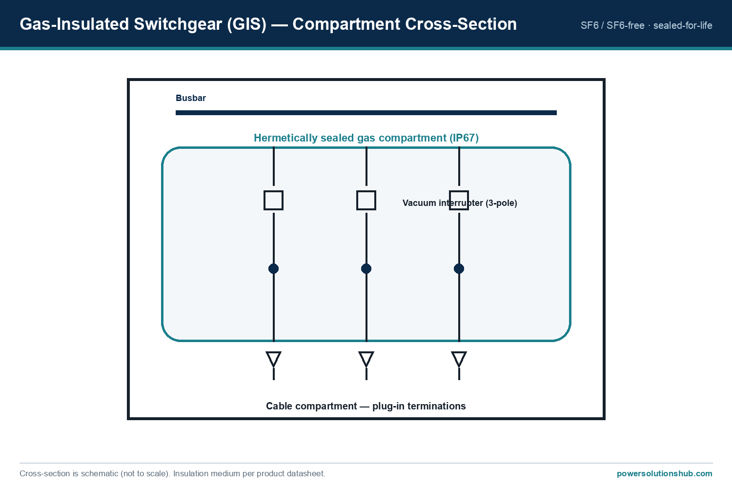
ABB Unisec MV Switchgear

ABB Unisec Medium Voltage Switchgear

UniSec Air is an air-insulated, SF6-free medium-voltage switchgear from ABB built for secondary power distribution up to 24 kV, 1250 A, and 25 kA, replacing sulfur hexafluoride with dry air as the insulating medium. This article covers the product’s ratings, service-continuity configurations, environmental profile, applicable standards, and typical deployment scenarios for utilities, industrial plants, and infrastructure projects across the Middle East and Gulf region including Egypt and Saudi Arabia, North Africa, the CIS, and Sub-Saharan Africa.

ABB Unisec MV Switchgear — schematic
ABB Unisec MV Switchgear — schematic.

What is UniSec Air Switchgear?

UniSec Air is ABB’s SF6-free medium-voltage secondary distribution switchgear, designed as a direct evolution of the established UniSec platform, using dry air insulation instead of sulfur hexafluoride gas. The switchgear employs a compact GSec Air switch disconnector and disconnector, with all active parts segregated inside a low-volume tank of less than 25 liters. This design supports the global transition away from high-GWP insulating gases while maintaining reliable breaking and switching performance through a dedicated vacuum interrupter.

Selection reference
Selection reference.

Why SF6-Free Switchgear Matters

Sulfur hexafluoride has historically been favored in switchgear for its excellent insulating properties and compact footprint, but SF6 carries a global warming potential of 24,300 times that of CO2, making it one of the most potent greenhouse gases in industrial use. Regulators, particularly in the European Union, are phasing out SF6 in medium-voltage equipment through binding legislation. UniSec Air is fully compliant with the EU F-gas regulation (EU) 2024/573, positioning buyers ahead of tightening environmental requirements without needing future retrofits.

The GSec Air switch disconnector and disconnector use a dry air insulation medium with a global warming potential of zero, combined with a dedicated vacuum interrupter for reliable breaking capacity. This eliminates risks tied to gas leaks or improper handling of hazardous insulating media, improving operator and environmental safety compared with SF6-filled equipment.

Product Scope and Ratings

UniSec Air is defined by the following rated parameters:

Parameter Standard Configuration With LSC2B Frontal Withdrawable Circuit Breaker Panel
Rated voltage Up to 24 kV Up to 24 kV
Rated current Up to 630 A Up to 1250 A
Rated short-time withstand current Up to 20 kA Up to 25 kA
Internal Arc Classification Up to IAC A FLR 20 kA Up to IAC A FLR 25 kA
Switch disconnector tank volume Less than 25 liters
Insulation medium GWP 0

These ratings allow UniSec Air to serve both standard low-current distribution feeders and higher-duty applications requiring elevated breaking capacity, simply by selecting the withdrawable circuit breaker panel configuration.

Types and Configurations

Service Continuity (LSC) Options

UniSec Air offers multiple service continuity classifications — LSC2B, LSC2A, and LSC2 — tailored to different operational needs. These configurations determine how much of the switchgear can remain energized while maintenance or extension work is performed on an adjacent panel, directly affecting uptime during servicing activities.

Frontal Withdrawable Circuit Breaker Panel (LSC2B)

The LSC2B frontal withdrawable circuit breaker panel is the configuration that unlocks the switchgear’s highest current and short-circuit ratings, raising rated current to up to 1250 A and short-time withstand current to up to 25 kA, alongside an internal arc classification of up to IAC A FLR 25 kA. This variant suits applications where higher fault-current withstand and load capacity are required.

Compatibility with UniSec

A key structural advantage is the compatibility between UniSec Air and the original UniSec platform. This allows operators with an existing UniSec installed base to expand or retrofit sections of their network with SF6-free panels without redesigning the entire switchgear lineup.

Selection Criteria

When specifying UniSec Air for a project, buyers and engineers should evaluate:

  • Required rated current — whether the standard rating up to 630 A is sufficient, or whether the higher 1250 A rating via LSC2B is needed.
  • Fault-current withstand needs — projects with higher prospective fault levels should confirm whether the 20 kA or 25 kA short-time withstand rating matches network requirements.
  • Internal arc safety requirements — sites with strict personnel-protection mandates should verify the applicable IAC classification and whether gas exhaust needs to be routed inside or outside the switchroom.
  • Service continuity class — LSC2B, LSC2A, or LSC2 selection based on how critical minimal-interruption maintenance is for the installation.
  • Regulatory compliance timeline — projects in jurisdictions moving toward F-gas restrictions benefit from specifying SF6-free equipment now rather than facing future retrofit costs.
  • Installation footprint and access — easy frontal and lateral access to MV cable connections simplifies installation, operation, and maintenance in constrained switchrooms.
  • Integration with existing assets — for brownfield projects, compatibility with the legacy UniSec range reduces engineering complexity.

Safety and Interlocking Features

UniSec Air incorporates a wide range of mechanical and electrical interlocks designed to enhance operator safety. Internal arc classification is paired with a gas exhaust system that can be configured according to the specific application, directing pressure relief either inside or outside the switchroom. Combined with the low-volume, segregated GSec Air tank design, these features reduce fault-related hazards for personnel working near the switchgear.

Environmental and Recycling Profile

UniSec Air is manufactured under quality and environmental management systems, with ABB complying with ISO 14001 standards. The switch disconnector and disconnector actuator is made of fully recyclable steel, and the product’s overall material breakdown for the SDC 500 mm unit demonstrates strong recyclability:

Material Recyclable Weight (kg) Share (%)
Steel Yes 191.1 78.2
Copper Yes 11.9 4.9
Aluminium Yes 1.2 <0.5
Plastics Yes 4.2 1.4
Total recyclables 208.5 85.0
Rubber No <0.5 <0.5
Epoxy No 35.6 14.5
Total non-recyclables 36.0 15.0

This recycling profile is based on the SDC 500 mm functional unit, giving procurement and sustainability teams a documented basis for end-of-life planning and environmental reporting.

Digital Tools and Documentation

ABB provides two digital tools to support UniSec Air specification and design work. BiMagic Designer is a web-browser-based application developed to digitalize the configuration activity of consultants and designers, allowing users to select switchgear characteristics, drag-and-drop typical units, and automatically generate project previews for export and collaboration. UniSec Pro is a tender and switchgear design tool that configures both UniSec Air and UniSec within the same interface, offering preconfigured standard solutions and complete technical/commercial documentation including editable project drawings.

Applications

UniSec Air is intended for secondary medium-voltage distribution, serving as the interface between incoming MV supply and downstream transformers or feeders in utility substations, industrial plants, commercial buildings, and infrastructure facilities. Its SF6-free design and compatibility with the legacy UniSec platform make it particularly relevant for utilities and EPC contractors that need to modernize distribution networks while meeting tightening environmental regulations. Buyers across the Middle East and Gulf region including Egypt and Saudi Arabia, North Africa, the CIS, and Sub-Saharan Africa can specify UniSec Air for new distribution projects or as a drop-in SF6-free upgrade path alongside existing UniSec installed bases.

Standards and Compliance

UniSec Air is developed in accordance with the requirements established by IEC 62271-200, the standard governing AC metal-enclosed switchgear and controlgear for rated voltages above 1 kV and up to and including 52 kV. Manufacturing is also carried out under quality and environmental management systems compliant with ISO 14001. The product’s SF6-free design further ensures alignment with the EU F-gas regulation (EU) 2024/573, giving specifiers confidence in long-term regulatory compliance.

Related guides

See also our guides on gas-insulated switchgear, ring main units and metal-clad switchgear.

What voltage and current range does UniSec Air cover?

UniSec Air is rated up to 24 kV, with rated current up to 630 A in the standard configuration and up to 1250 A when equipped with the LSC2B frontal withdrawable circuit breaker panel<!– 🔴 iddia: Rated voltage up to 24 kV; Rated current up to 630 A, up to 1250 A with LSC2B frontal withdrawable circuit breaker panel — kaynak ABB UniSec Air SF6 Free MV Switchgears.pd

Looking for Unisec Medium Voltage Switchgear?

Looking for high-quality unisec medium voltage switchgear? We provide expert engineering support and reliable products for all your medium voltage needs.

For quotations and requests: info@electricistanbul.com

WhatsApp: +90 501 076 69 91

Protection Relay Coordination and Selectivity

Protection Relay Coordination and Selectivity: A Step-by-Step Engineering Guide

“`

Protection relay coordination (also called selectivity or discrimination) is the engineering practice of setting the pickup current and time delay of series-connected protection relays so that only the relay closest to a fault operates first, isolating the smallest possible section of the network while all upstream relays remain in standby as backup. Achieving correct coordination requires a disciplined method: define fault currents at each network point, choose relay curve characteristics, calculate pickup and time settings, and verify the grading margin between adjacent devices on a time-current curve. This guide walks through the underlying formulas, a fully worked grading example between a transformer and an outgoing feeder relay, a practical settings-comparison table, common selection criteria, and the governing IEC/IEEE standards, with relevance for utilities and industrial operators across the Middle East and Gulf region including Egypt and Saudi Arabia, North Africa, the CIS, and Sub-Saharan Africa, where growing MV networks demand reliable fault discrimination.

Correct coordination matters because a badly graded protection scheme either trips too many breakers for a single fault (loss of selectivity, wide-area blackout) or trips too slowly (excessive equipment stress, arc-flash energy, and reduced personnel safety). Since protection relays at different voltage levels and feeder positions all “see” the same fault current with different magnitudes, coordination is fundamentally a mathematical exercise in comparing operating times along a common time-current curve, not a matter of trial and error in the field. Getting the calculations right at the design stage avoids costly re-commissioning and nuisance outages once the switchgear is energized.

Protection Relay Coordination and Selectivity — schematic
Protection Relay Coordination and Selectivity — schematic.

The method: time-current curves, pickup, and grading margin

Protection relay coordination rests on three linked calculations.

1. Pickup current (relay setting current). The relay’s minimum operating current, Is, is normally set as a multiple of the protected element’s rated current In:

Is = k × In

where k (often called the plug setting multiplier) is chosen above maximum expected load and below the minimum fault current the relay must detect, so that the relay does not trip on load or inrush but reliably picks up on internal faults.

2. Time-current characteristic. Most overcurrent relays (electromechanical or numerical, IDMT type) follow the standard inverse-time formula defined in IEC 60255-151:

t = TMS × [ k / ( (I/Is)^α − 1 ) ]

where: – t = operating time – TMS (or TDS in IEEE terminology) = time multiplier setting / time dial setting – I = fault current seen by the relay – Is = pickup current – k and α = constants that define the curve shape (standard inverse, very inverse, extremely inverse)

3. Grading margin (discrimination time). Between two relays in series — an upstream (backup) relay and a downstream (primary) relay — the operating time difference must exceed a minimum margin Δt to allow for breaker interrupting time, relay overshoot, and CT/measurement errors:

t_upstream − t_downstream ≥ Δt

A typical engineering margin used in grading studies is in the range of 0.3–0.5 seconds, covering breaker trip time, relay reset/overshoot, and a safety allowance — the exact value is a design choice validated against the specific relay and breaker combination, not a fixed universal constant.

Selection reference
Selection reference.

Worked example: grading a transformer relay against a feeder relay

Consider a simple radial system: a medium-voltage feeder relay (Relay F) protects an outgoing cable, and an upstream transformer relay (Relay T) protects the transformer feeding that busbar. Assume a 3-phase fault occurs just downstream of the feeder breaker, and the fault current measured by both relays (in a simple radial topology, both relays see essentially the same fault current) is I = 2000 A.

Step 1 — Determine rated currents and pickup settings. Suppose the feeder cable is rated so that its relay pickup is set at Is_F = 400 A, and the transformer relay pickup, based on the transformer’s rated current, is set at Is_T = 500 A.

Step 2 — Compute the current multiple of setting for each relay. For Relay F: I/Is_F = 2000/400 = 5.0 For Relay T: I/Is_T = 2000/500 = 4.0

Step 3 — Apply the standard inverse-time formula. Using the IEC standard inverse curve constants k = 0.14 and α = 0.02:

t = TMS × [0.14 / ((I/Is)^0.02 − 1)]

For Relay F with TMS = 0.10: (5.0)^0.02 = e^(0.02 × ln5) = e^(0.02 × 1.609) = e^0.0322 ≈ 1.0327 t_F = 0.10 × [0.14 / (1.0327 − 1)] = 0.10 × [0.14 / 0.0327] = 0.10 × 4.28 ≈ 0.428 s

Step 4 — Determine the TMS required for Relay T to grade above Relay F by the chosen margin. Target: t_T ≥ t_F + Δt = 0.428 + 0.4 = 0.828 s (using a 0.4 s grading margin for this example).

For Relay T: (4.0)^0.02 = e^(0.02 × ln4) = e^(0.02 × 1.386) = e^0.0277 ≈ 1.0281 t_T = TMS_T × [0.14 / (1.0281 − 1)] = TMS_T × [0.14 / 0.0281] = TMS_T × 4.98

Solving for TMS_T: TMS_T = 0.828 / 4.98 ≈ 0.166

So the transformer relay (Relay T) should be set with TMS ≈ 0.17 to clear the same fault in roughly 0.83 seconds, about 0.4 seconds after the feeder relay operates at 0.428 seconds — giving Relay F the first opportunity to isolate the fault and leaving Relay T as a time-graded backup. This is the essence of a coordination (grading) study: repeat Steps 1–4 for every fault location and every relay pair in the network, from the smallest downstream feeder outward to the highest upstream backup relay.

Settings comparison and coordination checklist

Parameter Relay F (feeder, downstream) Relay T (transformer, upstream)
Pickup current Is 400 A 500 A
Fault current seen 2000 A 2000 A
Multiple of setting (I/Is) 5.0 4.0
Curve type IEC standard inverse (k=0.14, α=0.02) IEC standard inverse (k=0.14, α=0.02)
TMS / TDS 0.10 ≈0.17
Computed operating time ≈0.428 s ≈0.83 s
Grading margin achieved ≈0.40 s

Note: all current, TMS, and time values above are illustrative computed figures for this worked example, not manufacturer-specific product ratings.

Selection criteria and common pitfalls

When performing a coordination study, engineers should evaluate:

  • Curve family selection. Standard inverse, very inverse, and extremely inverse curves each suit different fault-current profiles; extremely inverse curves are often preferred where fault current changes little with distance (e.g., near transformers), because they separate operating times more effectively at close-in faults.
  • Instantaneous elements. Many schemes add a high-set instantaneous stage above the maximum through-fault current to speed up clearance for close-in faults without compromising downstream selectivity — the instantaneous pickup must be set above the maximum fault current seen at the remote end of the protected zone to avoid mis-coordination.
  • CT accuracy and saturation. Current transformer class and knee-point voltage affect measured fault current accuracy, especially for high-magnitude faults; undersized CTs can distort grading margins.
  • Directional and differential elements. In looped or parallel-fed networks, plain time-graded overcurrent relaying may not achieve selectivity; directional overcurrent or unit protection (differential) schemes are then required.
  • Breaker interrupting time and relay overshoot. The grading margin must always account for the actual breaker clearing time and the specific relay’s overshoot/reset characteristics rather than a single assumed constant across all equipment.
  • Common pitfalls: neglecting motor starting or transformer inrush current when setting pickup (causing nuisance trips); ignoring changes in fault level after network reconfiguration; failing to re-run the grading study after equipment upgrades; and copying settings from one project to another without re-validating fault levels and CT ratios.

Coordination studies are typically documented for the full protection scheme covering incoming transformer relays, busbar protection, and outgoing feeder relays within [medium voltage switchgear](https://powersolutionshub.com/what-is-mv-switchgear-medium-voltage-switchgear/) assemblies, and settings are implemented on numerical protection relays associated with each circuit breaker, including those protecting distribution transformers.

Standards governing protection coordination

The characteristic curve equations and terminology used above follow IEC 60255-151 (Functional requirements for over/under current protection), which defines the standard inverse, very inverse, and extremely inverse time-current formulas used in coordination studies. IEEE C37.112 provides the equivalent standard inverse-time characteristics used in IEEE-based (ANSI) grading practice, particularly relevant where TDS (time dial setting) terminology is used instead of TMS. Overall protective relaying system requirements are also addressed in IEEE C37.90 and related application guides. Coordination studies for the associated switching equipment must also reflect the short-circuit withstand and breaking capability of the switchgear per IEC 62271-100/200, since relay time settings must never exceed the equipment’s rated short-time withstand duration.

Related guides

See also our guides on gas-insulated switchgear, ring main units and metal-clad switchgear.

What is the difference between protection coordination and selectivity?

The terms are largely synonymous in practice: coordination describes the calculation process (setting pickup and time delays), while selectivity describes the resulting outcome — only the relay nearest the fault trips, minimizing the de-energized area.

What is TMS or TDS in a protection relay?

TMS (Time Multiplier Setting, IEC terminology) or TDS (Time Dial Setting, IEEE terminology) is a multiplier applied to the base inverse-time curve equation, allowing the same curve shape to be shifted in time so that relays at different network positions can be graded against one another.

How much grading margin should be used between two relays?

The margin must cover breaker interrupting time, relay overshoot, and measurement tolerance; a commonly applied design range is roughly 0.3–0.5 seconds, but the exact value should be validated against the specific relay and breaker performance data for the project rather than assumed universally.

Why is a standard inverse curve used in the worked example instead of definite time?

Inverse-time curves automatically clear high-magnitude faults faster and low-magnitude faults slower, which naturally supports selectivity across a range of fault levels without needing a separate time setting for every fault scenario, unlike a fixed definite-time delay.

Do differential relays need time-current grading like overcurrent relays?

No. Differential (unit) protection compares currents at both ends of a protected zone and operates nearly instantaneously for an internal fault, independent of downstream relay settings, so it does not require time-graded coordination with other relays in the same way overcurrent schemes do.

What happens if two relays are not properly coordinated?

Poor coordination can cause both the primary and backup relay to trip simultaneously for the same fault (loss of selectivity, unnecessarily wide outage), or cause excessive fault clearance delay that increases thermal stress on cables and switchgear and raises arc-flash incident energy.

Does network reconfiguration affect an existing coordination study?

Yes. Any change in source impedance, transformer sizing, cable routing, or the addition of parallel feeders alters fault current magnitudes at every point in the network, so the grading study and relay settings must be reviewed and re-verified after such changes. “`

Looking for medium voltage protection relays?

Looking for high-quality medium voltage protection relays? We provide expert engineering support and reliable products for all your medium voltage needs.

For quotations and requests: info@electricistanbul.com

WhatsApp: +90 501 076 69 91