
A motor protection relay is a microprocessor-based protective device that continuously monitors the current, voltage, thermal state and sequence conditions of a medium-voltage induction or synchronous motor, and trips the associated circuit breaker or contactor when a fault or abnormal operating condition is detected. Selecting the right relay is not a catalogue exercise — it requires calculating the motor’s rated current, its thermal withstand behavior during starting, and the current-transformer ratios that feed the relay, then translating those numbers into correct protection settings. This guide walks through the method step by step, with a fully worked numeric example, and is relevant to engineers specifying pumping, compression, crushing and process-drive systems across the Middle East and Gulf (including Egypt and Saudi Arabia), North Africa, CIS and Sub-Saharan Africa markets, where MV motors above roughly 200 kW commonly move to dedicated numerical protection.
Why correct relay selection matters
An MV motor represents a large, expensive, often single-critical asset in a plant — a boiler feed pump, a compressor train, a conveyor drive. Two failure modes dominate the risk profile: thermal damage from prolonged overload or a stalled/locked rotor during starting, and electrical faults — phase, ground or internal winding faults — that must be cleared in milliseconds to limit iron and copper damage. An undersized or incorrectly set relay either nuisance-trips a healthy motor during normal starting (costing production) or fails to trip in time during a real fault (costing the motor itself, and potentially the upstream switchgear). Because motor starting current is many times the running current for a short but thermally significant period, motor protection relay setting is fundamentally a coordination problem between the motor’s thermal capability curve and the relay’s time-current characteristic — this is different from a simple feeder overcurrent relay.
The method: from nameplate data to relay setting
Step 1 — Determine the motor’s full-load current (FLC)
For a three-phase motor, the rated full-load current is derived from the nameplate rated power, voltage, power factor and efficiency:
I_FLA = P / (√3 × V × cosφ × η)
where P is rated shaft power in watts, V is rated line voltage, cosφ is rated power factor and η is rated efficiency. If the FLC is stamped on the nameplate, use that value directly — it already reflects the manufacturer’s design margins.
Step 2 — Establish the thermal withstand / starting characteristic
Every motor has a locked-rotor (starting) current, typically a multiple of FLC, and a maximum permissible locked-rotor time — the duration the stator and rotor windings can carry that starting current before insulation damage begins. This data (locked-rotor current multiple, hot/cold stall times) is supplied by the motor manufacturer and is the single most important input for setting the relay’s thermal overload and stall-protection curves — it must not be assumed generically.
Step 3 — Size the current transformers (CTs)
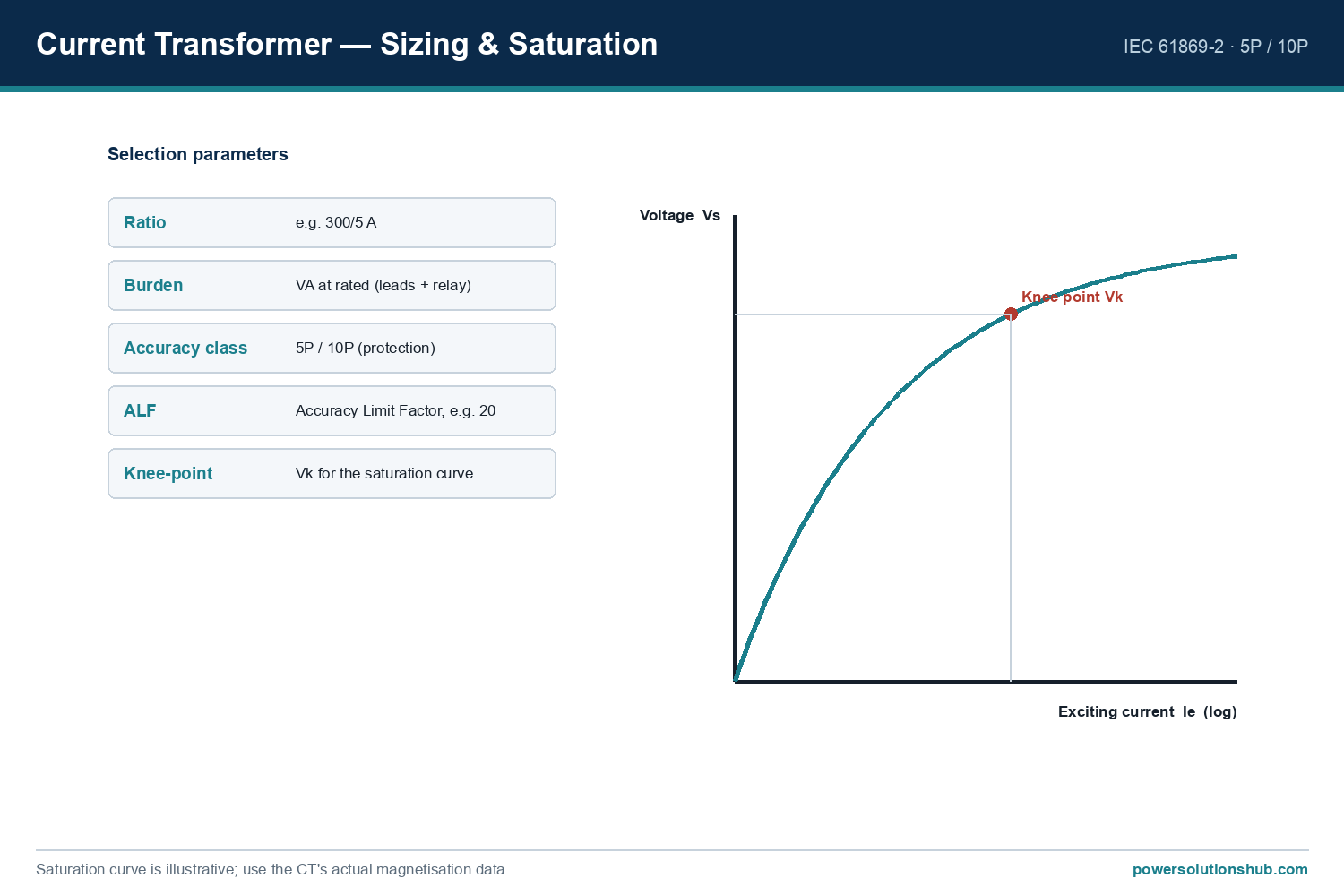
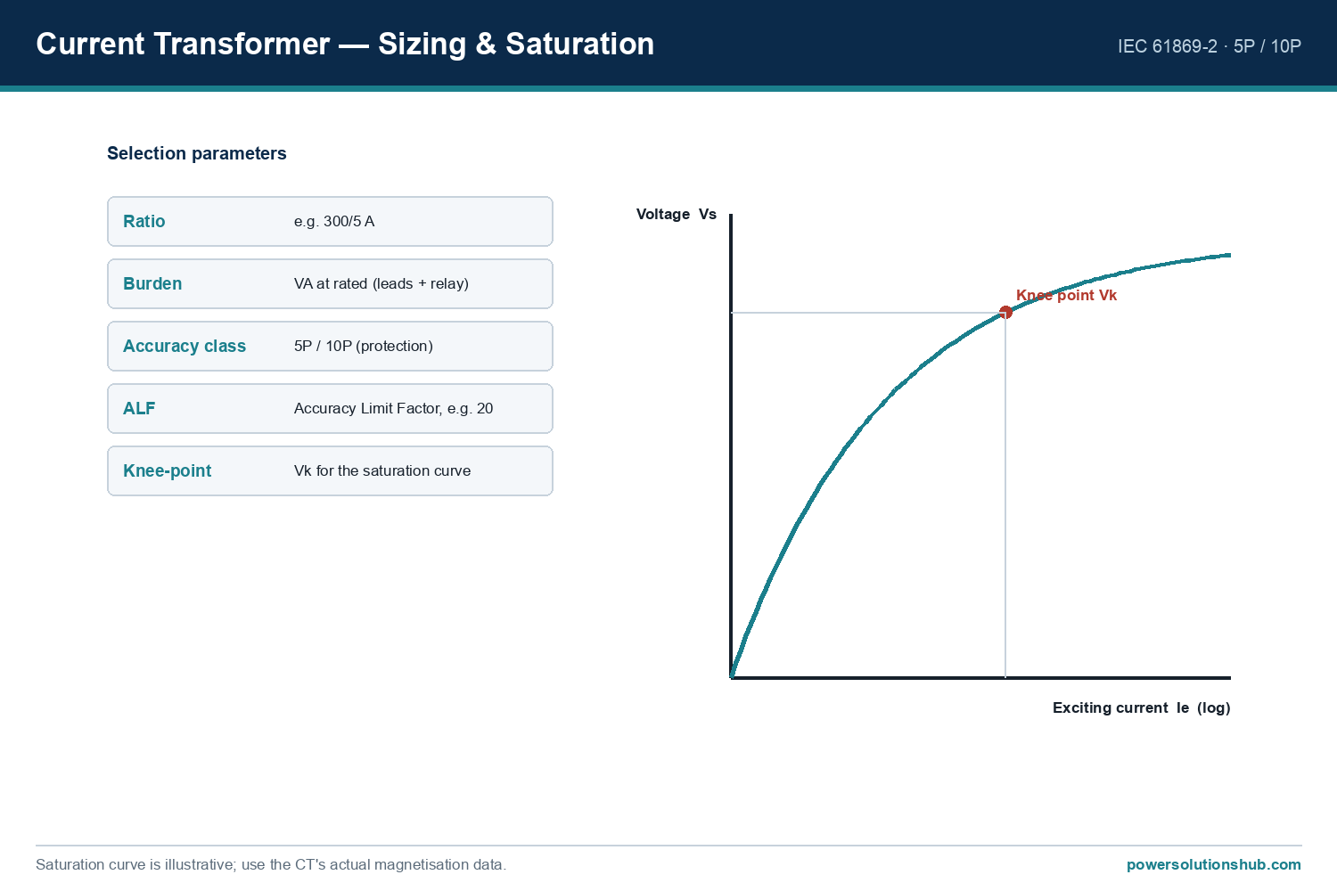
The relay measures current through dedicated protection-class CTs, not directly on the MV bus. CT primary rating should be chosen close to (and normally above) the motor FLC so the relay operates in a well-resolved part of its measuring range across the load range from light load to starting current, without saturating during the maximum through-fault current the CT must reproduce accurately.
Step 4 — Assign settings to each protection function
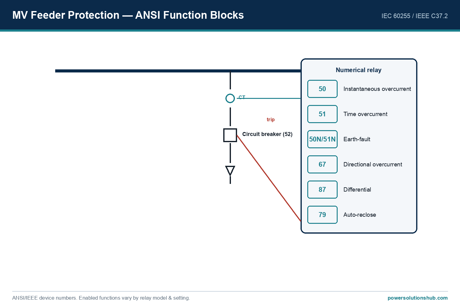
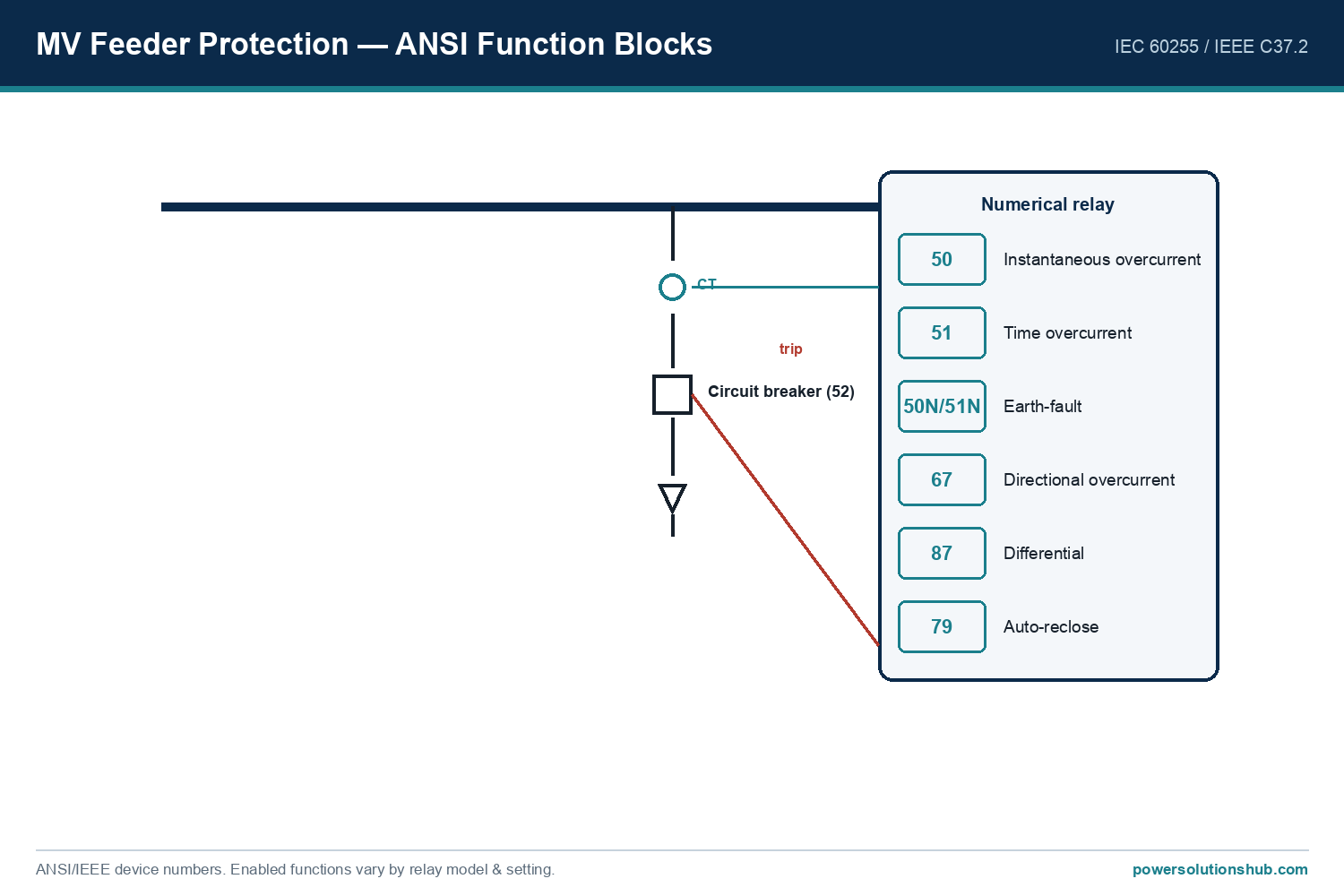
Once FLC, thermal/starting data and CT ratio are known, each protection element (thermal overload, locked rotor/stall, instantaneous and time overcurrent, earth fault, unbalance, differential if used) is set as a function of FLC or of the motor’s specific thermal curve — never as an arbitrary fixed current.
Worked example
Consider a 1000 kW, 11 kV MV induction motor with rated power factor cosφ = 0.87 and rated efficiency η = 0.95, driving a centrifugal pump.
Full-load current:
I_FLA = P / (√3 × V × cosφ × η) = 1,000,000 / (1.732 × 11,000 × 0.87 × 0.95) = 1,000,000 / (19,052 × 0.87 × 0.95) = 1,000,000 / 15,746 ≈ 63.5 A
Thermal overload setting (commonly applied practice is to set the relay’s thermal reference current between about 1.05 and 1.15 times FLC, to allow for measurement tolerance while still protecting the winding insulation):
I_set = 1.10 × 63.5 A ≈ 69.9 A
Illustrative locked-rotor / starting check: if the motor manufacturer states a locked-rotor current of 6 × FLC and a maximum hot stall time of, say, 12 seconds, the starting current would be:
I_LR = 6 × 63.5 A = 381 A
The relay’s stall/locked-rotor timer must then be set below the 12-second thermal withstand limit but above the motor’s normal accelerating time (for example, 8 seconds), so a healthy start is never blocked while a stalled rotor is still tripped before insulation damage occurs.
CT ratio selection: with an FLC of 63.5 A and an expected starting current of 381 A, a CT primary rated around 100 A (giving a secondary of 1 A or 5 A depending on relay input) keeps the motor operating comfortably within the CT’s linear accuracy range at both full load and starting current, while leaving margin below the CT’s rated accuracy limit factor for through-fault conditions.
Selection & setting comparison table
| Protection function | Common ANSI/IEC code | Setting basis | Purpose |
|---|---|---|---|
| Thermal overload | 49 | Function of motor thermal replica, referenced to FLC (illustrative: ~1.05–1.15 × FLC) | Prevent stator/rotor overheating under sustained overload |
| Locked rotor / stall | 51LR, 48 | Below motor’s stated hot/cold locked-rotor withstand time, above normal start time | Protect motor during a stalled or excessively long start |
| Short-circuit / instantaneous overcurrent | 50 | Set above maximum starting inrush, below relay/CT saturation limit | Fast clearance of phase faults |
| Earth/ground fault | 50N/51N, 64 | Low-set, based on core-balance CT sensitivity relative to FLC | Detect stator winding-to-earth faults |
| Negative-sequence / unbalance | 46 | Based on motor’s negative-sequence thermal (derating) capability | Protect against single-phasing / supply unbalance |
| Winding differential | 87M | Matched CT ratio each end, percentage-restrained slope | Internal phase-to-phase or phase-to-earth winding faults (larger motors) |
| RTD / bearing temperature | 38, 49 | Direct threshold from embedded stator/bearing sensors | Thermal protection independent of current measurement |
| Under/overvoltage | 27, 59 | Percentage of rated voltage | Protect against supply voltage excursions during start/run |
Selection criteria and common pitfalls
- Always use manufacturer motor data, not generic multipliers, for locked-rotor current and thermal withstand time — these vary significantly between motor designs and drive different relay curve selections.
- Match CT accuracy class to the protection function — a CT sized correctly for thermal/overload measurement may not have the accuracy-limit factor needed for a differential or high-set instantaneous element during a close-in fault.
- Coordinate the relay’s stall timer with actual starting time, especially for high-inertia loads (fans, crushers) where starting duration can approach the motor’s thermal withstand limit — a poorly coordinated relay will trip on every start.
- Account for restart and re-acceleration duty (e.g., after a brief supply dip) — successive-start counters and thermal memory functions prevent cumulative thermal damage from repeated starts.
- Differential protection (87M) is generally reserved for larger or critical motors, given the additional CT set required at both winding ends, while thermal, stall, overcurrent and earth-fault protection are considered standard on virtually all MV motor feeders.
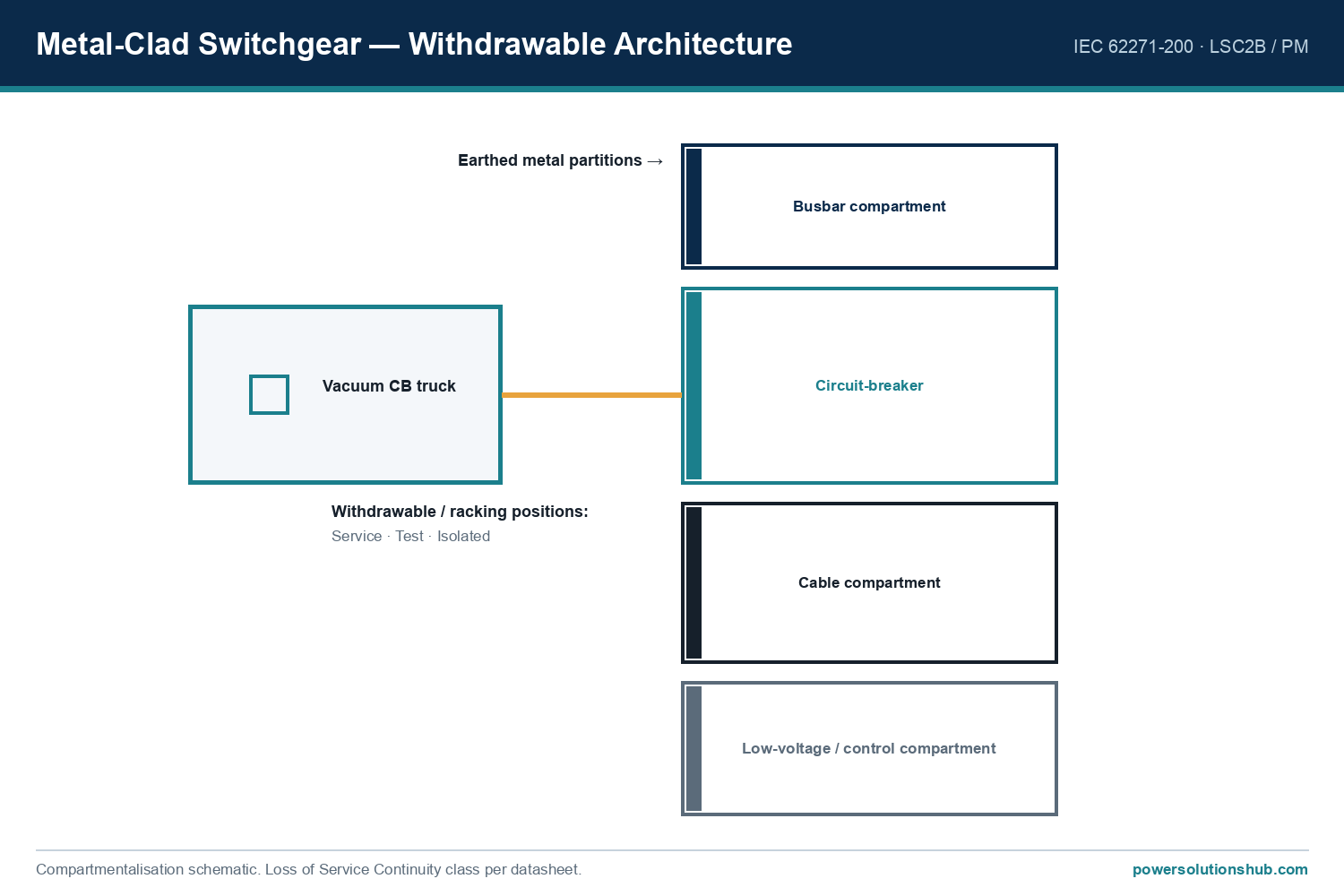
- Verify relay and CT selection alongside the associated MV switchgear and protection relay panel design, and check upstream coordination with feeder and transformer protection so that a motor fault is cleared selectively without unnecessary upstream tripping.
Governing standards
Motor protection relay selection is guided by IEC 60255 (functional and performance requirements for measuring relays and protection equipment), IEC 60034-1 (rating and performance requirements for rotating electrical machines, the source of the motor’s nameplate parameters used in sizing), and IEEE C37.96 – Guide for AC Motor Protection, which specifically addresses the protection philosophy, function selection and coordination practices for AC induction and synchronous motors. Current transformers used to feed the relay are selected per IEC 61869-2, which defines protection accuracy classes and accuracy-limit factors relevant to CT sizing described above.
Related guides
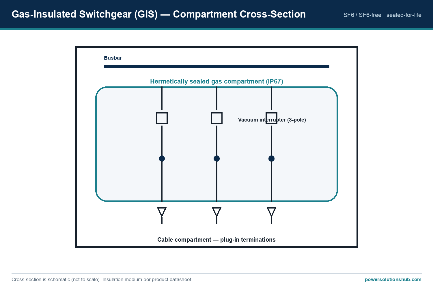
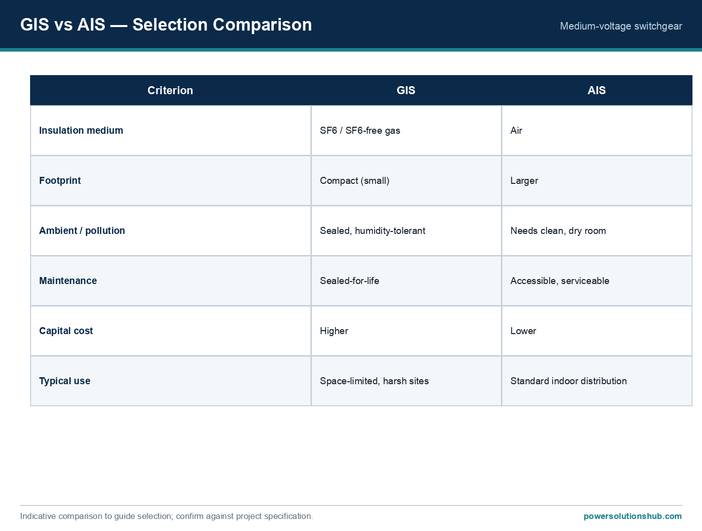
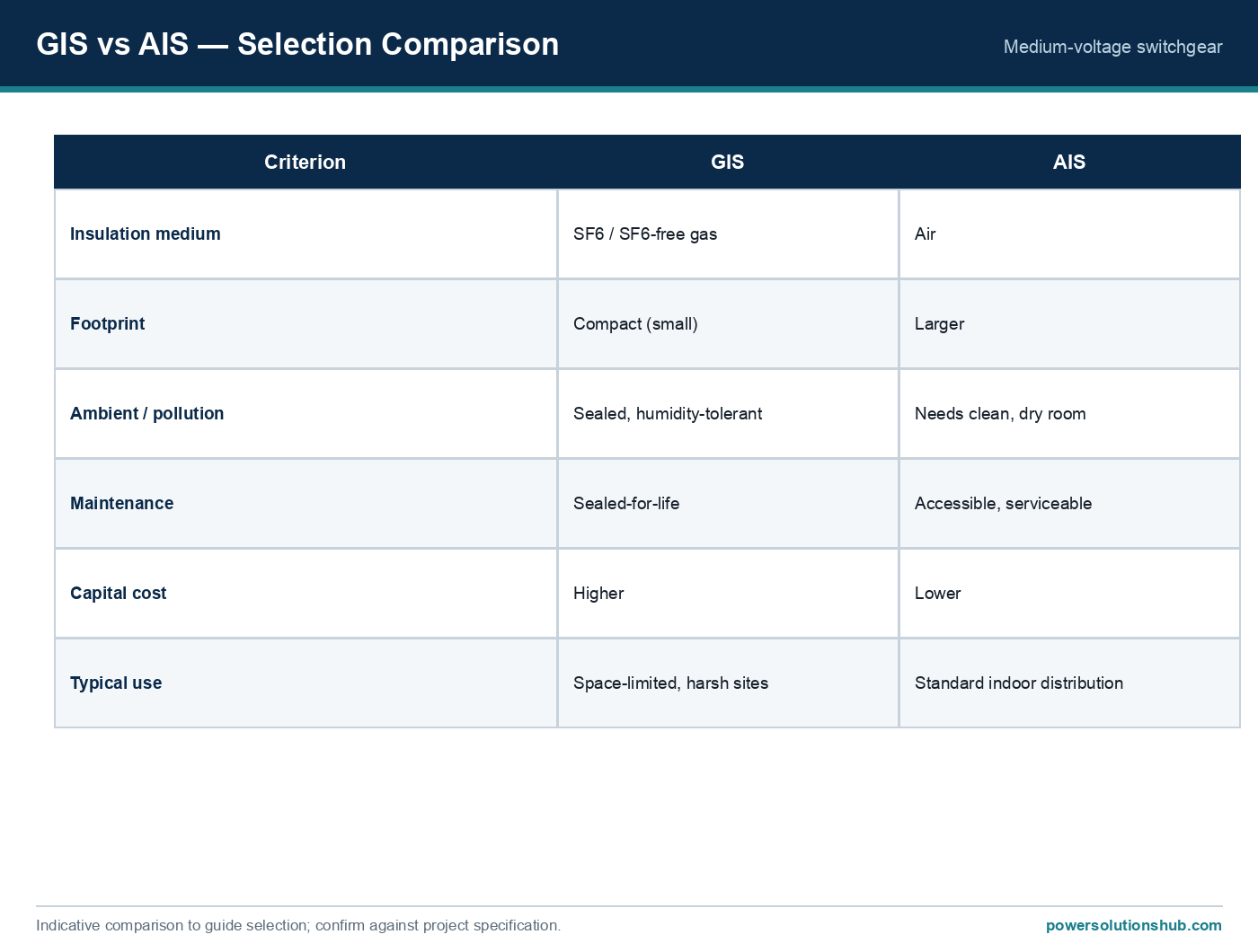
See also our guides on medium voltage switchgear, gas-insulated switchgear and ring main units.
What is a motor protection relay used for?
It is a numerical protective device that monitors an MV motor’s current, thermal state, voltage and sequence conditions, tripping the motor’s circuit breaker or contactor to prevent thermal or electrical damage during overload, stall, unbalance or fault conditions.
How do you calculate a motor’s full-load current for relay setting?
Using I_FLA = P / (√3 × V × cosφ × η) from nameplate power, voltage, power factor and efficiency, or by reading the FLC value directly from the nameplate when available.
Why is locked-rotor protection different from thermal overload protection?
Thermal overload protection responds to sustained running overload over minutes, while locked-rotor/stall protection specifically addresses the much higher current drawn during a stalled or prolonged start, which must be cleared within the motor’s much shorter thermal withstand time at that current level.
When is differential protection (87M) needed on an MV motor?
It is typically applied to larger or critical motors where the value of the asset justifies the additional CT sets required, to detect internal winding faults that overcurrent and thermal elements may not see quickly enough.
How is the CT ratio chosen for a motor protection relay?
The CT primary rating should be selected close to and generally above the motor’s full-load current so that both normal load and starting current fall within the CT’s accurate measuring range, while leaving margin for the accuracy-limit factor needed at fault current levels.
What standards apply to MV motor protection relays?
IEC 60255 covers the relay’s own functional requirements, IEC 60034-1 defines the rotating machine parameters used for sizing, IEEE C37.96 provides the motor protection application guide, and IEC 61869-2 governs the associated current transformers.
Can one relay protect several small motors, or is one relay needed per motor?
Best practice is one dedicated relay per MV motor feeder, since thermal, stall and differential settings must be individually matched to that motor’s own nameplate and starting characteristics; grouping motors behind a shared relay is generally reserved for low-voltage, non-critical applications.
Looking for medium voltage protection relays?
Looking for high-quality medium voltage protection relays? We provide expert engineering support and reliable products for all your medium voltage needs.
For quotations and requests: info@electricistanbul.com
WhatsApp: +90 501 076 69 91