

A prefabricated (compact) substation is a factory-assembled, type-tested power station package that integrates medium-voltage switchgear, a distribution transformer, and low-voltage distribution boards inside a single housing, ready for on-site installation with minimal civil works. This guide walks through the engineering logic behind selecting one — from load calculation to rated-current sizing, enclosure and protection-level choices, and the comparative trade-offs between kiosk, package, and RMU-based designs. It is written for utility, EPC, and industrial engineers working across the Middle East and Gulf region (including Egypt and Saudi Arabia), North Africa, the CIS, and Sub-Saharan Africa, where compact substations are widely deployed for rapid network expansion, renewable interconnection, and urban densification projects.
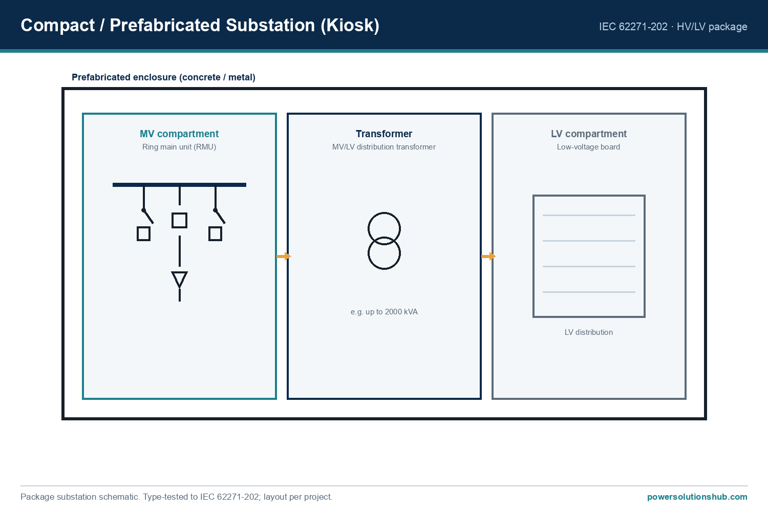
Why Prefabricated Substation Sizing Matters
Selecting a compact substation is not just a matter of picking a transformer rating off a catalogue page. An undersized unit overheats, trips, and shortens transformer life; an oversized one wastes capital, increases no-load losses, and may complicate protection coordination with upstream relays. Because the substation package bundles MV switchgear, transformer, and LV board as one coordinated unit, every component — busbar rated current, cable gland size, transformer impedance, and protection relay pickup — must be derived consistently from the same load and fault-current study. Getting this sequence wrong at the design stage is far more expensive to correct after factory assembly than during the selection phase.
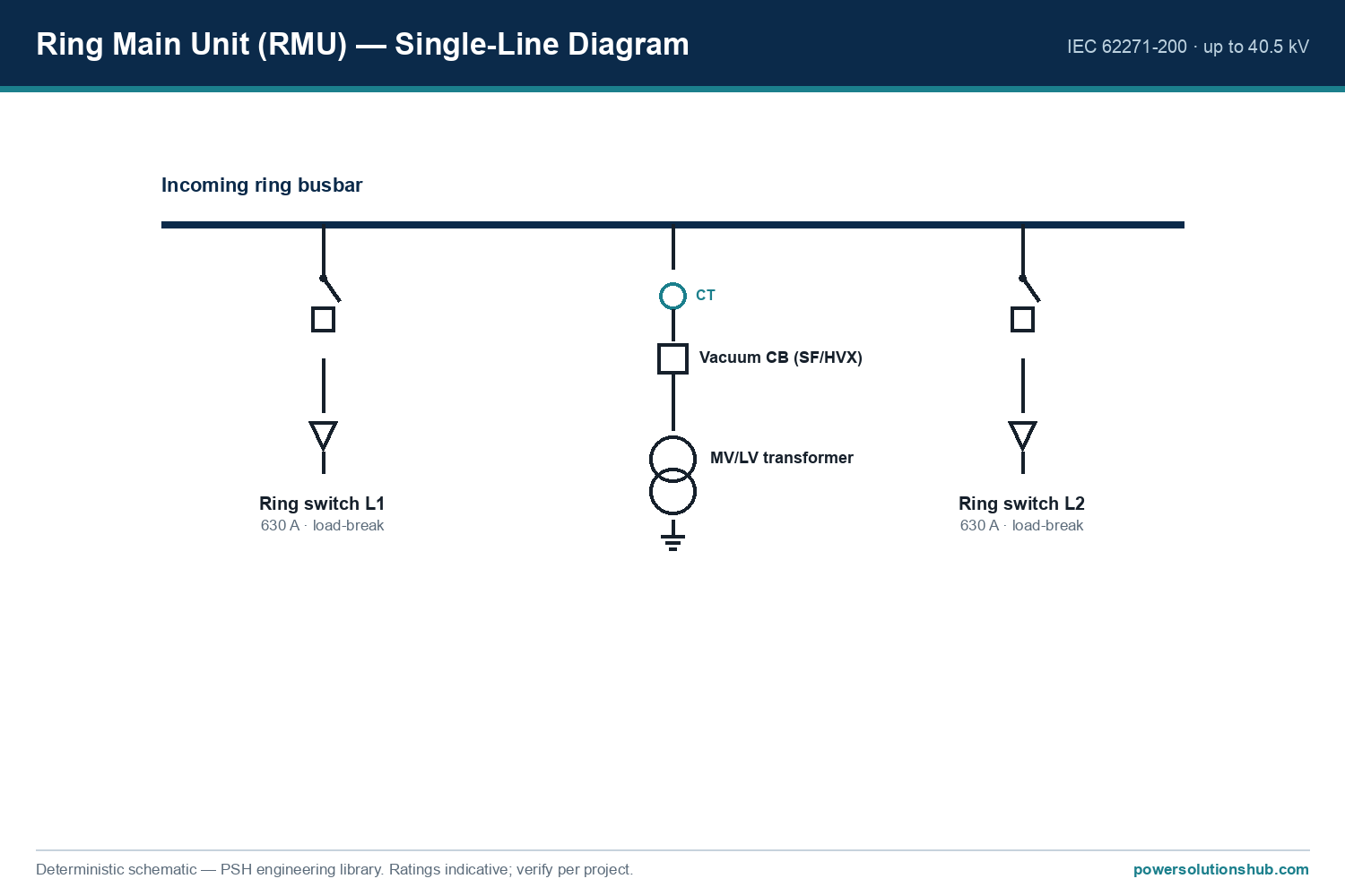
Method: The Core Formulas for Compact Substation Sizing
The selection process follows four main calculation steps.
1. Rated current from apparent power
The transformer (and therefore the switchgear incomer) must carry the rated current derived from the chosen apparent power S (kVA) at the system line-to-line voltage V (kV):
I (A) = S (kVA) / (√3 × V (kV))
2. Required transformer capacity from the load profile
S (kVA) = P (kW) / power factor (cos φ)
where P is the coincident active demand of all connected loads after applying diversity/demand factors.
3. Short-circuit current estimate for switchgear and busbar rating
A simplified per-unit approach:
I_sc (kA) ≈ I_rated / Z_pu
where Z_pu is the transformer’s per-unit impedance (as a decimal) and I_rated is the transformer’s rated secondary current. This is a first-order check; a full fault study should also include upstream source impedance and cable impedance for final protection settings.
4. Cable/feeder sizing check
Once the incomer current is known, outgoing feeder cables and LV board busbars are sized to carry the diversified load current with margin for future growth, typically by selecting the next standard cable cross-section above the calculated continuous current, derated for ambient temperature and installation method.
These four steps — demand, apparent power, rated current, and fault level — define the minimum electrical envelope that the compact substation enclosure, switchgear compartment, and transformer compartment must physically and thermally accommodate.
Worked Example: Sizing a Compact Substation for a Mixed-Use Site
Assume an industrial/commercial site with a coincident active demand of 850 kW at an average power factor of 0.85, to be supplied from an 11 kV medium-voltage network.
Step 1 — Apparent power demand
S = P / cos φ = 850 / 0.85 ≈ 1,000 kVA
This suggests selecting a standard transformer size of 1000 kVA (rounding up to the nearest commercially available rating, with headroom for diversity-factor uncertainty).
Step 2 — MV-side rated current (incomer to the compact substation)
I = S / (√3 × V) = 1,000 / (1.732 × 11) ≈ 52.5 A
This is the continuous current the MV switchgear incomer, bus, and cable termination inside the substation must be rated to carry without exceeding thermal limits.
Step 3 — LV-side rated current (assuming 0.4 kV secondary)
I_LV = 1,000 / (1.732 × 0.4) ≈ 1,443 A
This defines the minimum busbar and LV panel current rating on the low-voltage side of the package substation.
Step 4 — Approximate three-phase fault current at the LV terminals
Using a typical transformer per-unit impedance of 6% (Z_pu = 0.06) as an illustrative value for this calculation:
I_sc ≈ I_LV / Z_pu = 1,443 / 0.06 ≈ 24,050 A ≈ 24.1 kA
This approximate fault level (illustrative, based on an assumed 6% impedance — actual transformer nameplate impedance must be used in the final study) tells the engineer the minimum short-circuit withstand and breaking capacity the LV distribution board and any LV circuit breakers inside the compact substation must be specified to, and it also feeds into the upstream MV protection relay coordination study. For guidance on relay coordination and protection functions, see our protection relay hub page.
Selection & Comparison Table
| Decision Factor | Kiosk-type Compact Substation | Package/Containerized Substation | RMU-based Compact Substation |
|---|---|---|---|
| Typical application | Urban/residential distribution, limited footprint | Industrial sites, temporary/mobile power, renewable interconnection | Ring-main network extension, small commercial loads |
| Switchgear configuration | Fixed or withdrawable MV panel + transformer + LV board in one steel/concrete enclosure | Full MV switchgear + transformer + LV board inside a transportable container | Ring main unit (RMU) feeding a small integral or adjacent transformer |
| Civil works required | Minimal (concrete pad/foundation only) | Minimal to moderate (foundation + access) | Minimal |
| Expansion flexibility | Low — fixed internal layout | Moderate — modular container sections possible | Low to moderate depending on RMU bay count |
| Typical deployment speed | Fast (factory pre-tested) | Fast (factory pre-tested, truck-delivered) | Fast (compact footprint) |
| Best fit when… | Space is very limited and loads are predictable | Site is temporary, remote, or load will be relocated | Network is already ring-configured and load addition is small |
Selection Criteria and Common Pitfalls
1. Validate the demand/diversity factor before fixing transformer size. Using the instantaneous peak of individual loads without diversity typically oversizes the transformer and the whole substation footprint unnecessarily.
2. Confirm transformer impedance before finalizing switchgear fault ratings. As shown in the worked example, the assumed per-unit impedance has a direct, inverse effect on calculated fault current — a lower impedance value increases the fault current the switchgear must interrupt.
3. Check ambient and altitude derating. Compact enclosures have restricted ventilation compared with open installations; transformer and switchgear thermal ratings may need derating for high ambient temperature sites common across Gulf and Sub-Saharan African climates.
4. Match the LV board rating to the actual LV-side current, not the MV-side figure. Engineers sometimes mistakenly apply the MV incomer current when specifying LV busbars — the two values differ by the voltage transformation ratio, as shown in Steps 2–3 above.
5. Plan for future load growth within the enclosure’s physical limits. Because compact substations have fixed internal space, allow margin in cable gland sizes and spare breaker/feeder ways at the design stage rather than after factory manufacture.
6. Coordinate protection settings with the upstream network. The compact substation’s incoming protection relay must be graded against both the transformer’s fault withstand and the upstream feeder protection; see our switchgear hub page and transformer hub page for related selection guidance.
Standards and Compliance Notes
Compact and prefabricated substations are factory-built assemblies combining several product families, each governed by its own IEC standard: medium-voltage switchgear assemblies typically follow IEC 62271-200 (metal-enclosed AC switchgear for rated voltages above 1 kV), power/distribution transformers follow the IEC 60076 series, and low-voltage switchgear assemblies follow IEC 61439. The overall prefabricated substation enclosure and factory-assembled package arrangement is typically addressed by IEC 62271-202 (AC metal-enclosed switchgear and controlgear assemblies for rated voltages up to and including 52 kV — prefabricated substations), which specifically covers type-testing of the combined switchgear-transformer-LV board package as a single functional unit. Buyers should confirm which standard the vendor’s factory type-test certificate references for the specific package configuration being procured, since compliance claims vary by enclosure class, internal arc rating, and ingress protection level.
Related guides
See also our guides on gas-insulated switchgear, ring main units and metal-clad switchgear.
What is the first step in selecting a prefabricated substation?
The first step is establishing the coincident active demand (kW) of all loads to be served, applying an appropriate diversity/demand factor, then converting it to apparent power (kVA) using the expected power factor, as shown in the worked example above.
How do I know what current rating the MV switchgear inside the substation needs?
Calculate it from the chosen transformer’s kVA rating and the system line-to-line voltage using I = S / (√3 × V). This gives the continuous current the incomer, busbar, and cable terminations must be rated to carry.
Why does transformer impedance matter for compact substation selection?
Transformer impedance directly determines the approximate fault current seen at the LV terminals (I_sc ≈ I_rated / Z_pu). A lower impedance transformer produces a higher fault current, which raises the required short-circuit withstand rating of the LV board and influences upstream protection relay settings.
What’s the difference between a kiosk substation and a package/containerized substation?
A kiosk-type unit is typically a fixed steel or concrete enclosure suited to permanent urban/residential sites with limited footprint, while a package or containerized substation is a transportable unit often chosen for temporary, remote, or relocatable installations such as construction sites or renewable energy interconnection points.
Does ambient temperature affect compact substation sizing?
Yes. Compact enclosures have more restricted internal ventilation than open-air installations, so transformer and switchgear thermal ratings may require derating in high-ambient-temperature regions, which engineers must account for during the sizing step.
Which IEC standard governs prefabricated substations as a complete package?
IEC 62271-202 specifically addresses AC metal-enclosed switchgear and controlgear assemblies for rated voltages up to and including 52 kV in the prefabricated substation configuration, covering the combined switchgear, transformer, and LV board package as a type-tested unit.
Can a compact substation be expanded later if load grows?
Expansion flexibility is generally limited because the internal layout is fixed at the factory. Engineers should size spare feeder ways, cable gland capacity, and transformer headroom during the original design phase rather than relying on post-installation modification.
Looking for compact substations?
Looking for high-quality compact substations? We provide expert engineering support and reliable products for all your medium voltage needs.
For quotations and requests: info@electricistanbul.com
WhatsApp: +90 501 076 69 91