

Power factor correction (PFC) is the engineering practice of installing capacitive reactive power sources — typically capacitor banks — in parallel with inductive loads to raise the operating power factor of an electrical system closer to unity, thereby reducing the reactive current drawn from the supply. In practical terms, PFC lowers apparent power (kVA) demand for the same real power (kW) output, which cuts line losses, frees up transformer and cable capacity, and can eliminate utility reactive-power penalties. This guide walks through the underlying power triangle, a fully worked kvar sizing example, a comparison of correction methods, selection pitfalls, and the relevant standards, and is written for engineers evaluating PFC for industrial plants, substations, and distribution networks across the Middle East and Gulf region (including Egypt and Saudi Arabia), North Africa, the CIS, and Sub-Saharan Africa.
Why Power Factor Matters
Most industrial loads — induction motors, transformers, arc furnaces, welding sets, fluorescent/HID lighting ballasts — are inductive. They draw not only real (active) power, measured in kW, which does useful work, but also reactive power, measured in kvar, which sustains the magnetic fields in windings and does no useful work at the load itself. The vector sum of these two components is apparent power, measured in kVA, and this is what actually flows through generators, transformers, cables, and switchgear.
A low power factor means a larger share of the apparent power is reactive rather than active. The practical consequences are:
- Higher current for the same useful load — I ∝ kVA, so low PF means more amps flowing for the same kW delivered.
- Increased I²R losses in cables, transformers, and busbars.
- Reduced usable capacity of transformers and switchgear, since their kVA rating is shared between active and reactive power.
- Utility power factor penalties, applied in many grid codes when PF falls below a contractual threshold (commonly around 0.90–0.95, depending on the local tariff structure).
- Voltage drop on long feeders, since reactive current contributes to the I·X component of line impedance drop.
Correcting the power factor by installing capacitors locally compensates the inductive reactive power with capacitive reactive power, so less reactive current needs to travel from the source. This is why PFC is standard practice at the point of common coupling, at MV switchgear incomers, and directly at large motor terminals.
The Power Triangle and the PFC Formula
The three quantities — active power (P, kW), reactive power (Q, kvar), and apparent power (S, kVA) — relate through the power triangle:
S² = P² + Q²
Power factor, cos φ = P / S
The phase angle φ is the angle between voltage and current, and tan φ = Q / P.
To correct the power factor from an existing value cos φ₁ to a target value cos φ₂, the required capacitive reactive power is:
Qc = P × (tan φ₁ − tan φ₂)
where: – P = real power of the load (kW) – φ₁ = arccos(existing PF) – φ₂ = arccos(target PF) – Qc = capacitor bank rating required (kvar)
This formula is the single most important calculation in PFC engineering — it directly sizes the capacitor bank.
Worked Example: Sizing a Capacitor Bank
Consider an industrial load of P = 500 kW operating at an existing power factor of cos φ₁ = 0.75 (lagging), and the target is to raise it to cos φ₂ = 0.95.
Step 1 — Find the angles. φ₁ = arccos(0.75) = 41.41° φ₂ = arccos(0.95) = 18.19°
Step 2 — Find the tangents. tan(41.41°) ≈ 0.882 tan(18.19°) ≈ 0.329
Step 3 — Apply the formula. Qc = P × (tan φ₁ − tan φ₂) = 500 × (0.882 − 0.329) = 500 × 0.553 ≈ 276.5 kvar
So a capacitor bank rated at approximately 277 kvar is required to raise the power factor from 0.75 to 0.95 at this 500 kW load.
Step 4 — Check the apparent power reduction. Before correction: S₁ = P / cos φ₁ = 500 / 0.75 ≈ 666.7 kVA After correction: S₂ = P / cos φ₂ = 500 / 0.95 ≈ 526.3 kVA
The apparent power demand falls by roughly 140 kVA — meaning the same 500 kW load now requires about 21% less transformer/cable/switchgear capacity to supply, and the corresponding line current drops proportionally (I ∝ S at constant voltage).
This worked calculation is the template used for sizing any capacitor bank, whether a single LV capacitor at a motor terminal or an MV capacitor bank feeding from a switchgear bay.
Step/Comparison Table: PFC Methods
| Method | Typical application | Control response | Key consideration |
|---|---|---|---|
| Fixed capacitor bank | Constant reactive load (e.g., single large motor) | None (always connected) | Risk of over-correction (leading PF) at light load |
| Automatic switched capacitor bank (stepped) | Variable plant loads, substation incomers | Stepped, via contactors/relays, switched in stages | Needs a power factor controller/relay to switch steps |
| Detuned/tuned harmonic filter reactor + capacitor | Loads with significant harmonic content (VFDs, rectifiers) | Same as switched bank, plus filtering | Must be sized against resonance with system harmonics |
| Synchronous condenser | Large transmission-level reactive support | Continuous, dynamically adjustable | Higher capital cost, used mainly at grid/utility scale |
| Static VAR compensator (SVC) | Fast-changing loads (arc furnaces, cranes) | Continuous, near-instantaneous | More complex power electronics, higher cost |
For most industrial and commercial MV/LV installations, automatic switched capacitor banks controlled by a power factor relay are the standard solution, since load profiles vary through the day and a fixed bank risks leading power factor during low-load periods.
Selection Criteria and Common Pitfalls
When specifying a PFC solution, engineers should evaluate:
- Target power factor: usually set just above the utility’s penalty threshold (commonly in the 0.90–0.98 range) rather than exactly at unity, to avoid overcorrection risk.
- Load profile: a plant with highly variable loads needs automatic switched steps rather than a single fixed bank.
- Harmonic content: capacitor banks can resonate with background harmonics from variable frequency drives, UPS systems, or rectifiers. Where harmonic distortion is significant, detuned reactors in series with the capacitors are used to shift the resonant frequency away from characteristic harmonic orders.
- Switching device: capacitor banks are switched using contactors rated for capacitive inrush duty, or dedicated capacitor-duty circuit breakers/switches at MV level, coordinated with the [protection relay](/what-is-a-medium-voltage-protection-relay-mv-protection-relay/) scheme.
- Location: correction can be applied centrally (at the main incomer), in groups (per distribution board), or locally (at individual large motors) — local correction gives the greatest loss reduction on the cabling between the load and the correction point.
- Overcorrection risk: driving the power factor to leading (capacitive) conditions can cause voltage rise and is generally avoided; automatic controllers should de-step capacitors at light load.
- Transformer and switchgear headroom: PFC frees up kVA capacity, which should be verified against the rating of the upstream transformer and switchgear before assuming extra load can be added.
A frequent design mistake is sizing the capacitor bank purely from nameplate PF without accounting for the actual measured load profile, which can lead to either under-correction (penalties persist) or over-correction (voltage rise, leading PF penalties in some tariff structures).
Standards
Power factor correction equipment and shunt capacitor banks are generally engineered and tested with reference to IEC 60871 (shunt power capacitors) for capacitor units, while automatic PFC controllers and relays follow general LV/MV switchgear and control standards applicable to the installation. Utility power factor billing thresholds and penalty structures are set locally by the grid operator or regulator rather than by a single international standard, so project-specific tariff documentation should always be checked alongside the governing capacitor and switchgear standards.
Related guides
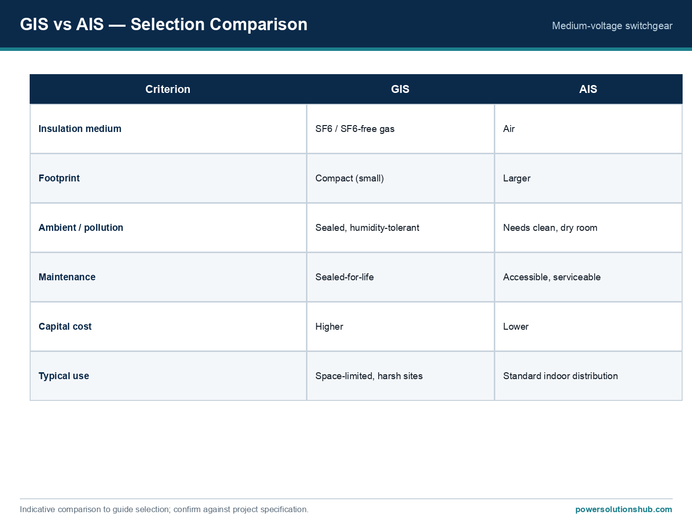
See also our guides on medium voltage switchgear, gas-insulated switchgear and ring main units.
What does power factor correction actually do?
It adds capacitive reactive power in parallel with inductive loads so the source supplies less reactive current for the same active power delivered, which reduces losses and apparent power demand.
What is a “good” power factor to target?
Most industrial PFC schemes target a value just above the local utility’s penalty threshold — commonly cited in the 0.90 to 0.98 range — rather than exactly 1.0, to avoid overcorrection into a leading power factor.
How do I size a capacitor bank in kvar?
Use Qc = P × (tan φ₁ − tan φ₂), where φ₁ and φ₂ are derived from the existing and target power factors, as shown in the worked example above.
Why can overcorrection be a problem?
Pushing the power factor to leading (capacitive) can cause voltage rise on the feeder and may itself attract a leading-PF penalty under some tariff structures, so automatic controllers de-step capacitors at light load.
Do I need harmonic filtering with my capacitor bank?
If the plant has significant harmonic-producing loads such as variable frequency drives or rectifiers, a detuned reactor in series with the capacitors is used to avoid resonance with those harmonic frequencies.
Where should capacitor banks be installed — centrally or locally?
Central correction at the main incomer corrects the bulk load cheaply, while local correction at individual large motors gives the greatest reduction in losses on the cabling feeding those specific loads; many plants use a mix of both.
Does PFC increase the load capacity of my existing transformer?
Yes — by reducing the reactive component of apparent power, PFC frees up kVA headroom on the same transformer and switchgear, though the available real power increase should always be checked against the transformer’s actual rating.
Looking for power factor correction and capacitor banks?
Looking for high-quality power factor correction and capacitor banks? We provide expert engineering support and reliable products for all your medium voltage needs.
For quotations and requests: info@electricistanbul.com
WhatsApp: +90 501 076 69 91