

Electrical panel thermal management is the engineering discipline of calculating, verifying and limiting the internal temperature rise of a switchgear or distribution assembly so that conductors, insulation and devices stay within their safe operating range under rated and site conditions. This guide walks through the heat-balance method used to predict temperature rise inside an enclosure, shows a fully worked derating example, and gives a practical table for sizing panels destined for hot-climate installations across the Middle East and Gulf region including Egypt and Saudi Arabia, North Africa, the CIS states, and Sub-Saharan Africa, where high ambient temperature is the single most common cause of premature nuisance tripping and insulation ageing.
Why thermal management decides the real rating of a panel
A switchgear or low-voltage distribution board is nameplate-rated at a reference ambient temperature, almost always 35°C average over 24 hours per the governing assembly standard. Every ampere of current flowing through busbars, contacts, cables and protection devices generates I²R loss, and that loss has to leave the enclosure as heat through natural or forced convection and radiation from the external surfaces. If the site ambient is hotter than the reference temperature, or if the enclosure is more sealed than assumed in the design (a high IP rating reduces natural ventilation), the same rated current will produce a higher internal temperature than the manufacturer verified in type test. The practical consequence is that the panel must be derated — operated below its nameplate current — to keep conductor and insulation temperatures inside safe limits. Ignoring this step is one of the most frequent causes of overheating failures, accelerated insulation ageing and spurious thermal-relay trips in hot-climate MV/LV installations.
The heat-balance method: how temperature rise is calculated
The physical principle behind every panel thermal calculation is a heat balance: in steady state, the total internal power loss generated by current-carrying parts and devices must equal the heat removed from the enclosure surfaces by convection and radiation.
Step 1 — Total internal power loss (Q). Q is the sum of all I²R losses in busbars, cables, contacts, and the fixed losses of installed devices (relays, meters, auxiliary transformers):
Q = Σ(I² × R) + Q_devices
Step 2 — Effective heat-dissipating surface (A_e). Only the enclosure surfaces that can freely exchange heat with ambient air count toward A_e; surfaces against a wall or inside a closed room contribute less, which is why the calculation method in the governing assembly standard applies correction factors depending on installation (free-standing, wall-mounted, in a row of panels) and on the degree of internal segregation between compartments.
Step 3 — Temperature rise (ΔT). In a simplified natural-convection model, the internal-to-ambient temperature rise is proportional to the heat flux through the effective surface:
ΔT = Q / (h × A_e)
where h is a combined convective-plus-radiative heat transfer coefficient (W/m²·K) that depends on enclosure material, surface finish/emissivity, ventilation openings and mounting arrangement.
Step 4 — Hot-spot temperature. Hot-spot temperature = Ambient temperature + ΔT
This value must stay below the maximum permissible operating temperature of the most thermally sensitive component in the assembly — typically the insulation class of cables, the contact temperature limit of switching devices, or the maximum operating temperature stated by the relay/meter manufacturer.
Worked example: deriving the derating factor for a hot-climate site
Assume a three-phase LV distribution panel is verified by the manufacturer at its nameplate rated current of 1000 A at the standard 35°C reference ambient, reaching an allowable internal temperature rise of 30°C above ambient — i.e. the hottest internal point stays at the equipment’s maximum permissible operating temperature of 65°C at full rated current under standard reference conditions.
Because, in this simplified first-principles model, power loss scales with the square of the current (Q ∝ I²) and the enclosure’s convective/radiative heat removal capacity (h × A_e) is essentially constant for a given design, the temperature rise can be written as:
ΔT = C × I²
Solving for the constant C from the manufacturer’s reference point:
C = ΔT / I² = 30°C / (1000 A)² = 3 × 10⁻⁵ °C/A²
Now consider a Gulf-region substation room where the design ambient temperature is 50°C instead of 35°C. The maximum permissible hot-spot temperature of the equipment is still fixed at 65°C, so the allowable temperature rise above the new, hotter ambient shrinks:
ΔT_allowable (50°C site) = 65°C − 50°C = 15°C
Using the same constant C, the maximum current the panel can now safely carry is:
I_max = √(ΔT_allowable / C) = √(15 / 3×10⁻⁵) = √500,000 ≈ 707 A
Derating factor = I_max / I_rated = 707 / 1000 ≈ 0.71
So a panel nameplate-rated at 1000 A in a 35°C reference environment should be derated to roughly 71% of its nameplate current — about 707 A — when continuously operated in a 50°C ambient, simply to preserve the same thermal margin to the component’s maximum permissible operating temperature. This is a simplified, illustrative calculation; real assemblies are verified against the detailed temperature-rise method and correction factors defined in the governing assembly standard, but the proportional relationship between ambient temperature rise and current capability is the same physical principle engineers must respect when specifying equipment for hot climates.
Derating factor vs. ambient temperature (illustrative table)
Using the same constant C derived above (C = 3 × 10⁻⁵ °C/A², hot-spot limit 65°C), the derating factor for a range of site ambient temperatures is:
| Site ambient temperature | Allowable ΔT (to 65°C hot-spot limit) | Max current (A) | Derating factor vs. 1000 A nameplate |
|---|---|---|---|
| 30°C | 35°C | ≈1,080 A | ≈1.08 (no derating needed) |
| 35°C (reference) | 30°C | 1,000 A | 1.00 |
| 40°C | 25°C | ≈913 A | ≈0.91 |
| 45°C | 20°C | ≈816 A | ≈0.82 |
| 50°C | 15°C | ≈707 A | ≈0.71 |
| 55°C | 10°C | ≈577 A | ≈0.58 |
Figures are computed from the worked-example model above for illustration; actual derating must be confirmed against the specific panel’s verified temperature-rise test report.
The table shows why the gap between a 35°C “standard” rating and a 45–50°C real desert or coastal-Gulf ambient is not a minor correction — it can remove 20–30% of usable current capacity, which is why panels for the GEO region (Middle East and Gulf including Egypt and Saudi Arabia, North Africa, CIS, Sub-Saharan Africa) should always be specified against the actual project design ambient, not a generic catalogue rating.
Selection criteria and common pitfalls
- Specify the real site ambient, not the catalogue default. A panel rated at 35°C reference must be derated, oversized, or force-ventilated for a 45–55°C design ambient typical of outdoor kiosks and unconditioned switch rooms.
- Check enclosure degree of protection against ventilation. A higher ingress protection rating (sealed, gasketed doors) reduces natural airflow and raises internal temperature rise for the same power loss; sealed panels usually need internal fans, heat exchangers, or air-conditioning units to compensate.
- Account for installation arrangement. A panel installed in a row, against a wall, or inside a small plant room has a smaller effective dissipating surface than a free-standing unit in open air, and the standard’s correction factors must be applied.
- Do not confuse continuous thermal rating with short-time fault withstand. Short-circuit thermal withstand (I²t) is a separate, very high-energy, very short-duration event governed by fault level studies — see our switchgear hub page — while thermal derating concerns continuous, steady-state operating current.
- Internal segregation (form of separation) affects airflow between compartments. More internally segregated designs may trap heat in individual compartments even if the overall enclosure is adequately ventilated.
- Protection relay settings must track the derated current, not the nameplate value. Overcurrent and thermal-overload protection should be coordinated to the actual safe operating current at site ambient — see our protection relay guide for coordination practice.
- Transformer room heat load adds to panel ambient. Where panels share a room with a distribution transformer, the transformer’s own losses raise the room ambient further; consult our transformer hub page when sizing ventilation for combined transformer-and-panel rooms.
Governing standards
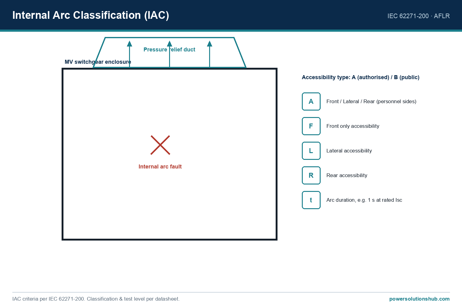
Low-voltage switchgear and controlgear assemblies (distribution boards and panels) are verified for temperature rise under the IEC 61439 series (general rules and specific requirements for assemblies), which defines the reference ambient temperature, the permitted methods for verifying temperature rise (by test, by calculation, or by comparison with a reference design), and the correction factors for installation and ventilation conditions. Medium-voltage metal-enclosed switchgear assemblies are covered separately under the IEC 62271 series, which includes its own temperature-rise and internal arc requirements, while short-circuit thermal and dynamic withstand calculations are typically cross-checked against IEC 60909 fault-current methodology. Where a specific numeric rated value for a product is required, it should always be confirmed on the manufacturer’s type-test report rather than assumed from a generic standard table.
Related guides
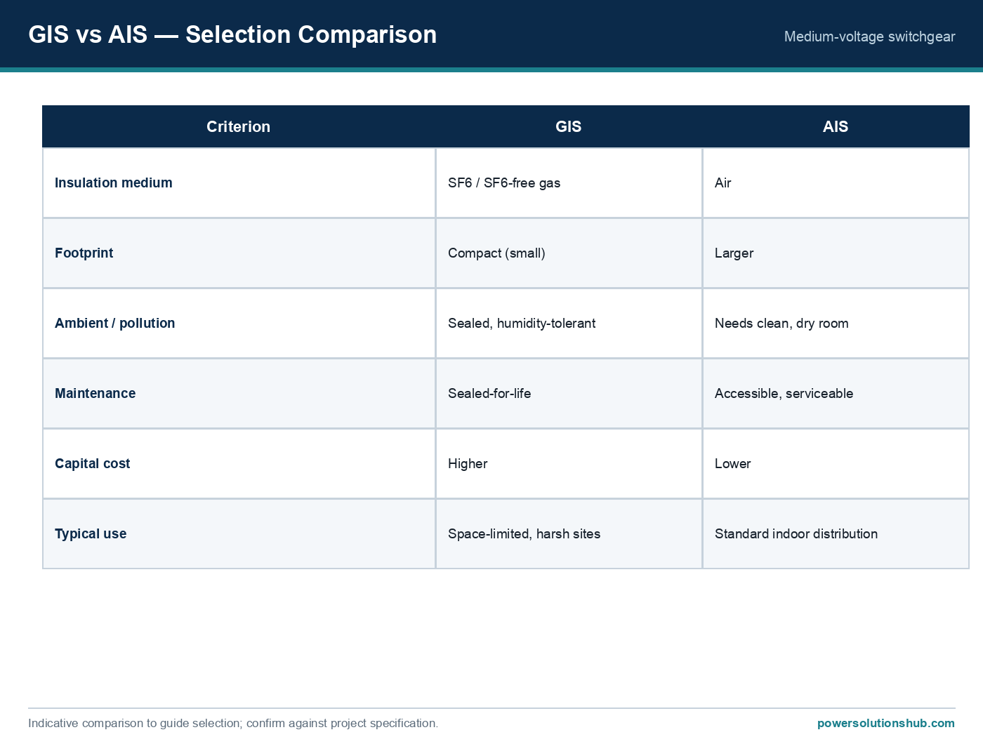
See also our guides on medium voltage switchgear, gas-insulated switchgear and ring main units.
What is the reference ambient temperature used for panel thermal ratings?
Assembly standards typically verify nameplate current at a standard reference ambient (commonly 35°C as a 24-hour average); any site ambient above that reference requires a derating calculation as shown above.
Why does a sealed (high IP) panel run hotter than a ventilated one at the same current?
A sealed enclosure blocks the natural airflow that would otherwise carry heat away by convection, so the same internal power loss produces a higher internal temperature rise; sealed panels often need forced ventilation or cooling units to compensate.
Is thermal derating the same as short-circuit derating?
No. Thermal derating concerns continuous steady-state current and long-term temperature rise, while short-circuit thermal withstand concerns a very brief, very high-energy fault event (I²t) evaluated separately under fault-current standards.
How much should I derate a panel for a 50°C desert ambient?
It depends on the specific equipment’s verified temperature-rise curve, but the first-principles worked example above illustrates a derating factor on the order of 0.7 (roughly 30% current reduction) relative to a 35°C reference rating — always confirm against the manufacturer’s test data.
Does panel colour or surface finish matter for cooling?
Yes qualitatively — surface emissivity affects the radiative component of heat transfer, and manufacturers account for this in the heat-transfer coefficient used in temperature-rise calculations.
Can forced ventilation or air conditioning avoid the need for derating?
Yes — adding fans, louvres, heat exchangers or air conditioning increases the effective heat removal capacity (h × A_e in the formula), which raises the current the panel can safely carry at a given ambient, effectively reducing or eliminating the derating penalty.
Where does protection relay thermal-overload setting fit into this calculation?
The thermal-overload or overcurrent protection setting should be coordinated to the panel’s actual derated safe current at site ambient, not the generic nameplate value, to avoid both nuisance tripping and unprotected overheating — see our protection relay coordination guide for details.
Looking for electrical panels and distribution boards?
Looking for high-quality electrical panels and distribution boards? We provide expert engineering support and reliable products for all your medium voltage needs.
For quotations and requests: info@electricistanbul.com
WhatsApp: +90 501 076 69 91