DC Power System Guide

DC Power System Guide: Battery Rectifiers for Medium-Voltage Substations

A DC power system is the independent, battery-backed low-voltage supply that keeps protection relays, circuit-breaker trip/close coils, SCADA/RTU equipment, and emergency indication energized during a loss of the incoming AC auxiliary supply, so that a substation can still trip a faulted feeder or close a breaker even in a total blackout. In practical terms, a DC power system is built around three elements: a rectifier/charger that converts incoming AC to regulated DC, a stationary battery bank that stores autonomy, and a DC distribution board that fans this power out to the protection, control and communication loads of the substation. This pillar article walks through the main architectures, battery technologies, selection criteria, typical applications, and the standards framework that governs this equipment, so that procurement and engineering teams across the Middle East and Gulf region (including Egypt and Saudi Arabia), North Africa, CIS countries, and Sub-Saharan Africa can specify a DC system correctly for their substation or industrial facility.
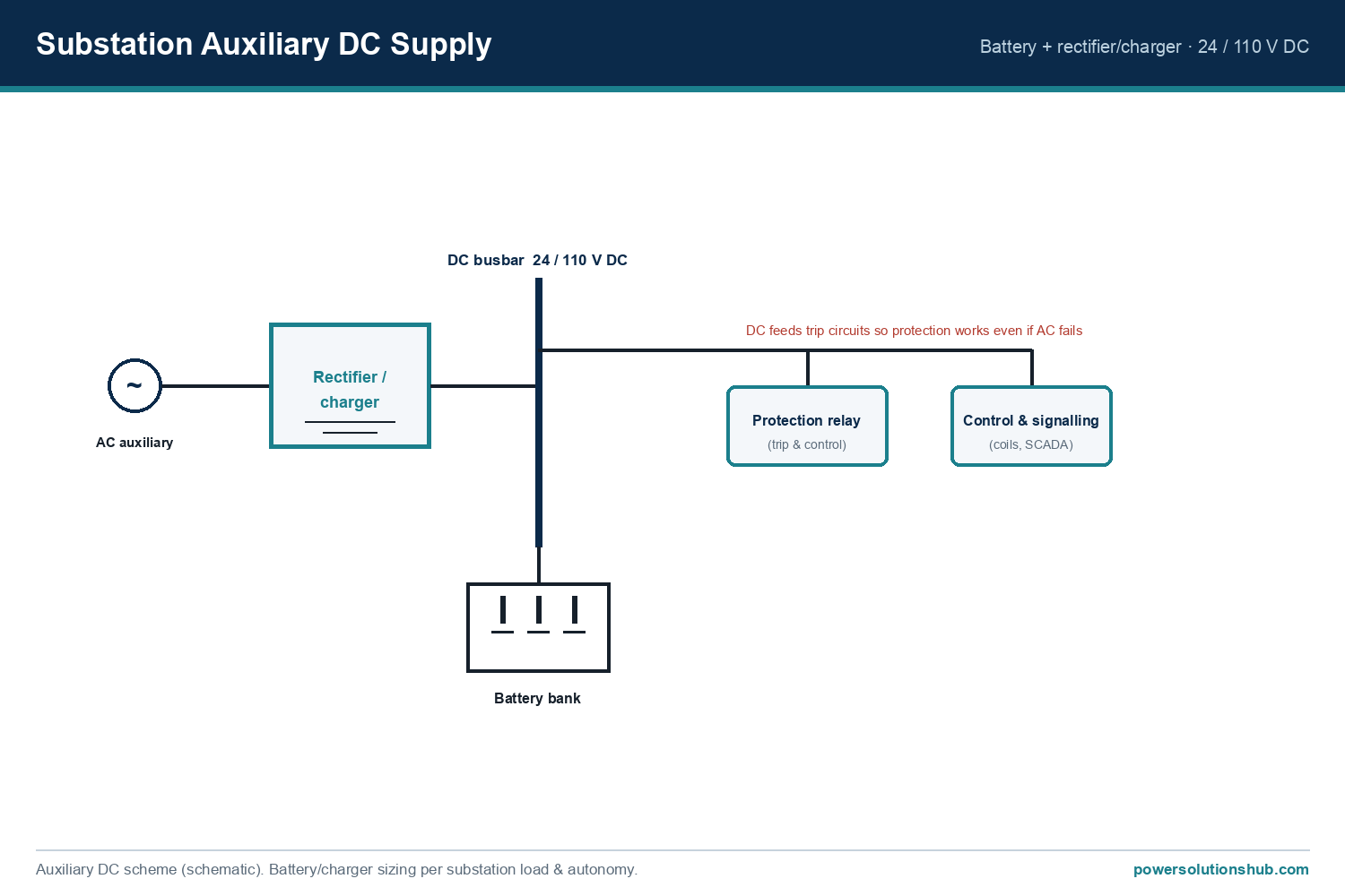
DC Power System Guide — schematic
DC Power System Guide — schematic.

Why Every MV Substation Needs a Dedicated DC Power System

Medium-voltage switchgear itself is normally passive equipment — it does not generate the energy needed to trip a breaker on fault, to hold a protection relay awake, or to keep a SCADA gateway reporting status. All of that control energy comes from the station’s DC power system. If the AC auxiliary supply that feeds the rectifier is lost — for example during a wide-area outage — the battery bank must be able to carry the full protection, tripping and monitoring load on its own until either the AC supply returns or an operator intervenes. This is why DC systems are engineered as dedicated, redundant assets rather than treated as an afterthought to the switchgear order.

Typical loads fed from a substation DC bus include:

  • Protection relay logic and trip circuits for MV/HV circuit breakers
  • Spring-charging motors and closing/opening solenoids on withdrawable circuit breakers
  • SCADA, RTU, and communication gateway power supplies
  • DC emergency lighting and alarm/annunciation panels
  • Motor operators on disconnectors, earthing switches and ring main unit switches

A well-designed DC power system therefore sits at the intersection of protection engineering, power electronics, and battery technology — which is why buyers should evaluate rectifier, battery and distribution components together rather than as separate purchases.
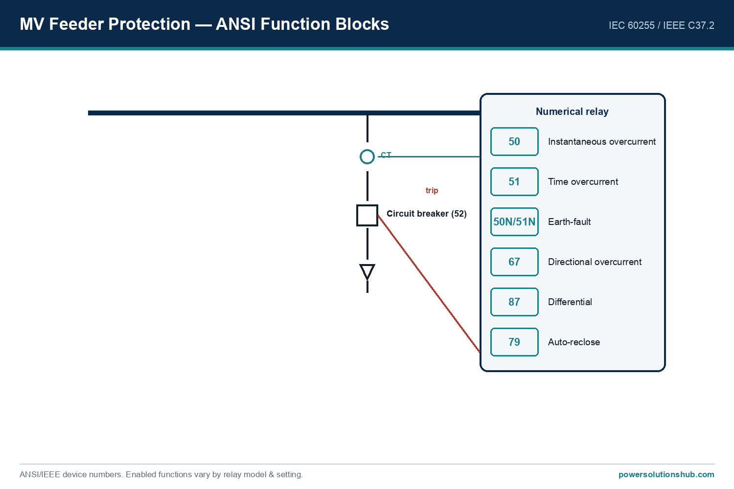
Selection reference
Selection reference.

Core Architecture: Rectifier, Battery Bank, and DC Distribution

Battery charger / rectifier module — Converts incoming single- or three-phase AC into regulated DC output, both to float-charge the battery continuously and to directly supply the connected DC loads under normal conditions. Modern rectifier modules are typically modular and hot-swappable, allowing redundant units to be added for N+1 style resilience without shutting down the DC bus.

Stationary battery bank — Provides ride-through autonomy when the AC supply to the rectifier is interrupted. The battery must be sized so it can support the connected protection, control and communication load for a defined autonomy period, plus a momentary high-current pulse for breaker tripping or closing operations.

DC distribution board — Fans the regulated DC output to individual protection and control circuits through fuses or miniature circuit breakers, with insulation monitoring to detect earth faults on the DC network before they can cause a mis-operation or loss of protection.

Monitoring and alarm module — Continuously supervises battery voltage, charging current, insulation resistance and rectifier health, raising alarms for the operator well before a fault condition could compromise the substation’s protection scheme.

Battery Technology Options for DC Power Systems

Selecting the right battery chemistry is one of the most consequential decisions in a DC power system, because it drives maintenance regime, footprint, expected service conditions, and total cost of ownership.

Valve-Regulated Lead-Acid (VRLA) batteries — Sealed-for-life design, low maintenance, compact footprint, and widely used where ambient temperature can be reasonably controlled. VRLA batteries are a common default choice for standard substation and switchgear auxiliary supply applications due to their favorable balance of cost and ease of installation.

Vented (flooded) Nickel-Cadmium (Ni-Cd) batteries — Recognized for robustness in wide temperature swings and harsh industrial environments, tolerant of deep discharge cycling, and generally associated with a longer service life than VRLA in demanding conditions, at the cost of a periodic topping-up maintenance regime and a larger installation footprint.

Lithium-based stationary batteries — Increasingly specified where space is constrained and where lower weight and faster recharge are priorities; adoption in MV substation DC systems is growing but still requires careful attention to protection, monitoring and thermal management design.

The table below summarizes the qualitative trade-offs buyers should weigh — no fabricated numeric ratings are used here; actual voltage, capacity and autonomy figures must always be confirmed against the manufacturer’s project-specific datasheet.

Attribute VRLA (sealed lead-acid) Vented Ni-Cd Lithium-based
Maintenance regime Sealed-for-life, minimal upkeep Periodic electrolyte/topping maintenance Low maintenance, BMS-managed
Footprint Compact Larger, heavier Most compact
Temperature tolerance Moderate, sensitive to heat Wide tolerance, robust Requires thermal management
Typical duty Standard substation/switchgear auxiliary supply Harsh industrial/utility environments, deep cycling Space-constrained, modern retrofits
Recharge characteristic Standard float/boost charging Slower recharge, robust cycling Faster recharge capability

Selection Criteria: How to Specify a DC Power System

1. Load profile and duty cycle — List every DC-fed device (relays, trip coils, motor operators, SCADA, lighting) and separate the continuous “standing” load from the momentary high-current pulses needed for breaker operation, since the rectifier and battery must be sized for both.

2. Required autonomy — Define how long the battery bank must support the full load with no AC input, based on the site’s realistic restoration time and the criticality of the installation (a remote unmanned substation typically demands longer autonomy than a manned industrial plant with fast standby generation).

3. Redundancy level — Decide whether a single rectifier module is acceptable or whether an N+1 configuration of hot-swappable rectifier modules is required so that a single module failure does not interrupt battery charging.

4. Battery chemistry vs. environment — Match VRLA, Ni-Cd, or lithium technology to the expected ambient temperature range, ventilation, available floor space, and the site’s ability to perform periodic maintenance.

5. Monitoring and communication — Confirm the DC system can report battery voltage, insulation status, and rectifier alarms back to the station SCADA/RTU, ideally with remote diagnostics for unmanned or hard-to-access sites.

6. Insulation and earth-fault supervision — Verify the distribution board includes continuous insulation monitoring, since an undetected earth fault on the DC bus can defeat protection tripping exactly when it is needed most.

7. Physical integration with switchgear — Coordinate cabinet dimensions, cable entries and communication interfaces with the MV switchgear or RMU supplier so the DC system integrates cleanly into the substation control building or outdoor kiosk.

Applications of DC Power Systems

Utility MV/HV substations — Feeding protection relays, breaker trip circuits, and SCADA at grid substations where uninterrupted control power is essential for fault clearance and remote operation.

Industrial plants with MV switchgear — Supporting motor control centers, ring main units and MV switchboards in oil & gas, mining, cement, water treatment and heavy manufacturing facilities.

Renewable energy substations — Providing DC control power for collector substations at solar and wind farms, where sites are often unmanned and rely heavily on remote monitoring.

Data centers and critical infrastructure — Backing up MV/LV switching equipment where any loss of protection or control power carries a high operational risk.

Rail and transit traction substations — Supplying signaling, protection and control loads that must remain energized independent of the traction supply status.

Standards and Compliance Notes

DC power systems for substations are engineered against equipment-specific standards covering stationary battery design, charger performance, and DC distribution safety, which are distinct from the switchgear standards that govern the MV breakers and busbars themselves. Because DC systems, batteries and rectifiers form a different equipment class from AC switchgear, buyers should ask suppliers to confirm the specific product standards applicable to the battery chemistry and charger design selected for their project, rather than assuming that MV switchgear standards automatically extend to the DC auxiliary supply. A reputable supplier will document compliance for the rectifier module, the battery bank, and the DC distribution board as separate, traceable items within the overall substation compliance file.

Related guides

See also our guides on gas-insulated switchgear, metal-clad switchgear and air-insulated switchgear.

What is the difference between a battery charger and a rectifier in a DC power system?

In substation terminology the two terms are often used interchangeably: the rectifier module converts AC to DC and also performs the charging function for the battery bank, maintaining it in a float-charged, ready-to-discharge state while simultaneously supplying the connected DC loads.

How long should a substation battery bank be able to support the load without AC input?

Required autonomy is project-specific and depends on the criticality of the site, the realistic time to restore AC supply, and the load profile; this figure should be defined in the project specification and confirmed with the battery manufacturer rather than assumed from a generic industry default.

Can lithium batteries replace VRLA or Ni-Cd batteries in existing substations?

Lithium-based stationary batteries can be used in retrofit or new-build DC systems where compact footprint and lower weight are priorities, but the battery management system, protection and thermal design must be engineered specifically for the application rather than swapped in as a drop-in replacement.

Why is insulation monitoring important on a DC distribution board?

An undetected earth fault on an ungrounded DC bus can, in some fault combinations, prevent a protection relay from tripping a breaker correctly; continuous insulation monitoring allows the operator to detect and clear a first earth fault before it compounds into a protection failure.

What is N+1 redundancy in a battery charger/rectifier system?

N+1 redundancy means installing one more rectifier module than the number strictly required to carry the load, so that if a single module fails, the remaining modules continue to charge the battery and supply the DC bus without interruption.

Does a DC power system need to be sized for momentary high-current pulses, not just steady load?

Yes — circuit breaker tripping and closing operations, and spring-charging motors, draw short but significant current pulses on top of the continuous standing load, and both the rectifier and battery must be sized to handle these pulses without an unacceptable voltage dip.

How should a DC power system be integrated with existing MV switchgear or ring main units?

Integration should be coordinated early with the switchgear supplier so that cabinet dimensions, cable routing, communication protocols and control voltage levels are aligned, avoiding costly rework once the switchgear and DC system arrive on site separately.

Looking for Battery Rectifier / DC Systems?

Looking for high-quality battery rectifier / dc systems? We provide expert engineering support and reliable products for all your medium voltage needs.

For quotations and requests: info@electricistanbul.com

WhatsApp: +90 501 076 69 91
Schneider MCset Metal Clad Switchgear

Schneider MCset Metal Clad Switchgear

MCset is a metal-clad, air-insulated medium-voltage switchgear range manufactured by Schneider Electric, engineered for public and industrial power distribution networks that require compartmentalized safety, high reliability, and native digital connectivity. This article covers the MCset Active and MCset Active Plus generations, their technology base, selection criteria, applications, and compliance notes for procurement teams. Buyers across the Middle East and Gulf region including Egypt and Saudi Arabia, North Africa, the CIS countries, and Sub-Saharan Africa increasingly specify metal-clad MV switchgear of this class for utility substations, industrial plants, and critical infrastructure projects where uptime and safety documentation are commercial requirements.

Schneider MCset Metal Clad Switchgear — schematic
Schneider MCset <a href="https://powersolutionshub.com/metal-clad-switchgear/">Metal Clad Switchgear</a> — schematic.

What Is MCset Metal Clad Switchgear?

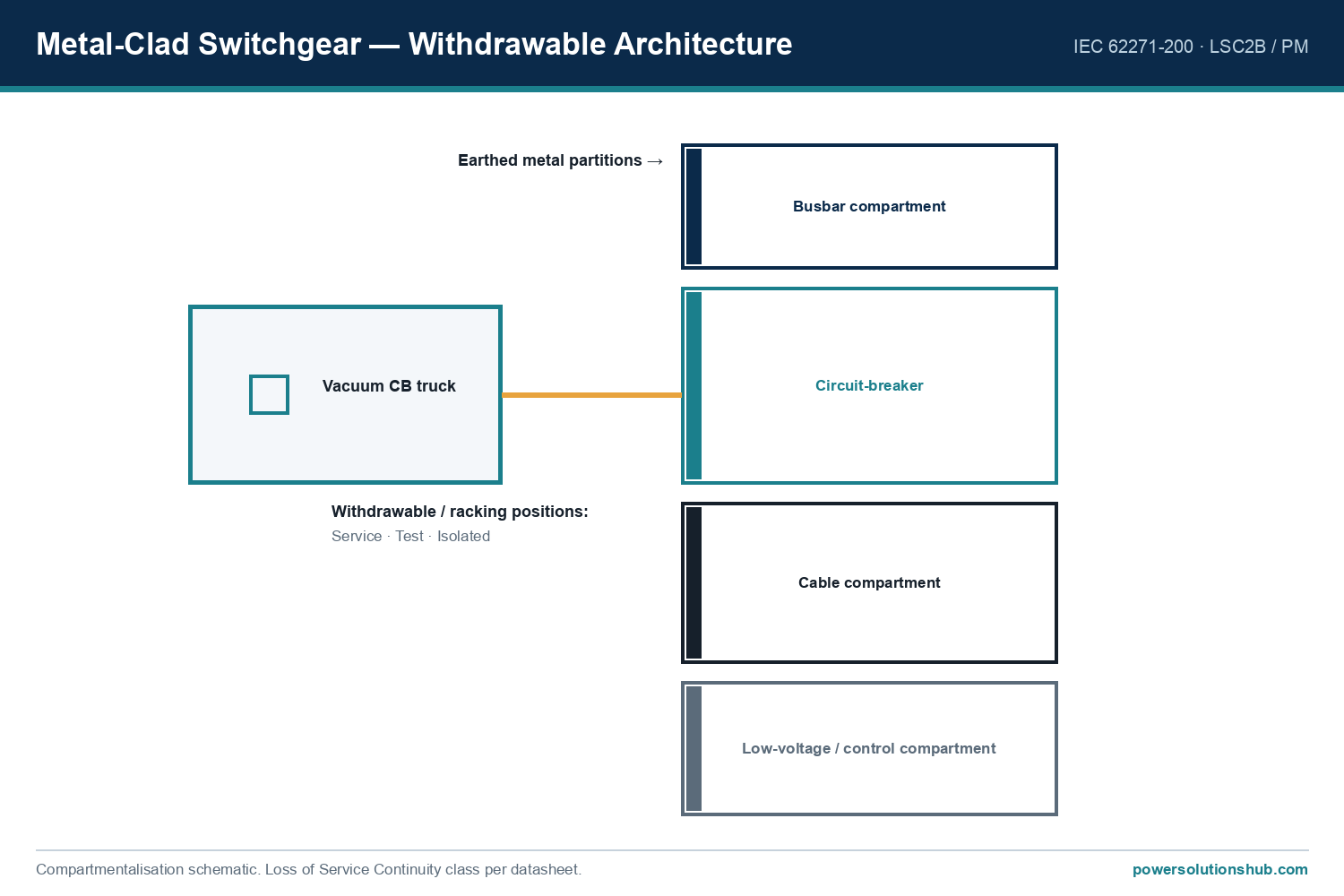
MCset belongs to Schneider Electric’s air-insulated switchgear family, positioned for medium-voltage distribution applications where each functional unit — circuit breaker, contactor, metering, or earthing device — is housed in its own metal-enclosed, compartmentalized cubicle. This is the defining characteristic of “metal-clad” construction: physical segregation between the busbar compartment, the circuit-breaker compartment, and the cable compartment, which limits the propagation of an internal fault and improves operator safety during maintenance.

The current generation, marketed as MCset Active and MCset Active Plus, is described in the manufacturer’s catalogue as air-insulated switchgear rated up to 24 kV , while the broader MCset product family extends to air-insulated switchgear rated up to 36kV . This means specifying engineers can align the exact MCset variant with the voltage class required by the project, from distribution substations to higher-voltage industrial interconnection points.

A distinguishing technical feature noted for the range is the use of a middle rolling circuit breaker design , a withdrawable-type mechanism that facilitates circuit-breaker racking, testing, and maintenance access without disturbing the fixed busbar and cable connections — a functional benefit consistent with metal-clad switchgear best practice.

Selection reference
Selection reference.

MCset Active vs MCset Active Plus: Range Variants

Schneider Electric structures the current MCset generation into two tiers, both built on the same air-and-digital switching philosophy but differing in the depth of embedded monitoring and remote-operation capability.

MCset Active is described as a natively connected MV switchgear platform, embedding essential condition-monitoring sensors and connectivity features directly at the factory, so that no additional field engineering or commissioning of sensing hardware is required on site. It targets customers who want digital visibility of busbar and circuit-breaker health with a simplified specification and ordering process.

MCset Active Plus is positioned for 24/7, mission-critical operations. It extends the Active platform with additional remote-operation features — including remote-controlled circuit breakers, remote-controlled earthing switches, and optional internal arc-flash detection — allowing operators to perform switching, earthing, and racking operations from outside the arc-flash zone. Active Plus also supports partial-discharge monitoring when combined with a dedicated expert monitoring service, giving asset owners an early-warning capability for insulation degradation.

Both variants are built around Schneider Electric’s air-based switching and vacuum/pure-air isolation technologies, moving away from SF6 gas insulation; the manufacturer references an SF6-free technology direction for its latest MV ranges to reduce the CO2 footprint of the equipment .

Selection Criteria for MCset Metal Clad Switchgear

When evaluating MCset — or any metal-clad switchgear — for a project, buyers should weigh the following factors:

  • Required voltage class: confirm whether the project needs the 24 kV-class configuration or a higher-rated variant within the up-to-36kV family, since this determines cubicle dimensions and insulation clearances.
  • Digital connectivity requirement: Active for essential condition monitoring, or Active Plus where remote operation from outside the arc-flash zone and partial-discharge monitoring are contractual requirements.
  • Application segment: utility substations, industrial process plants, marine/offshore installations, or data-center power trains each have different duty-cycle and space constraints that MCset’s compartmentalized, modular cubicle architecture is designed to accommodate.
  • Sustainability documentation: Green Premium™ labelling provides RoHS/REACh compliance data and Product Environmental Profiles, useful for tenders requiring environmental transparency; Schneider Electric states that more than 75% of its product sales offer this level of material and regulatory transparency .
  • Lifecycle service model: availability of an EcoCare membership plan for condition-based maintenance and predictive alerts, relevant for owners planning long-term operational-expenditure budgets.
  • Track record and manufacturing pedigree: Schneider Electric cites more than 50 years of experience in medium-voltage switchgear design and in-house component engineering as a resilience factor for the MCset platform .

Comparison Table: MCset Active vs MCset Active Plus

Feature MCset Active MCset Active Plus
Air-insulated switchgear voltage class covered up to 24 kV up to 24 kV
Broader MCset family voltage range up to 36kV up to 36kV
Circuit breaker mechanism Middle rolling circuit breaker Middle rolling circuit breaker
Embedded condition monitoring Factory-installed essential sensors Full condition monitoring + Partial Discharge monitoring option
Remote operation outside arc-flash zone Digital logbook, remote monitoring Remote circuit breaker/earthing switch operation + optional internal arc-flash detection
Manufacturer design pedigree 50+ years of MV switchgear experience 50+ years of MV switchgear experience

Applications of MCset Metal Clad Switchgear

According to the manufacturer’s catalogue, MCset is engineered for a broad set of operating environments:

  • Power supply companies — public utility distribution networks with varying operational requirements.
  • Industrial facilities — oil and gas, chemical, automotive, mining/mineral/metal, and process engineering plants.
  • Infrastructure — airports, tower blocks, and water treatment plants.
  • Marine — cruise ships, container and LNG carriers, offshore platforms, and naval vessels.
  • Data centers — HV/MV, MV/MV, and MV/LV substations, plus on-site power generation for extra-large data centers, cloud, and service-provider facilities.

This spread of use cases is consistent with metal-clad switchgear’s role as the interface point between incoming MV feeders and downstream distribution or generation assets, where compartmentalized construction and digital monitoring both add measurable operational value.

Standards and Digital Ecosystem Compliance

MCset metal clad switchgear is positioned within the international framework for compartmentalized MV switchgear, generally referenced under the metal-clad switchgear standard IEC 62271-200 , which defines type-testing and compartmentalization requirements for AC metal-enclosed switchgear and controlgear above 1 kV. Buyers issuing tenders should request the specific type-test certificates for the exact MCset configuration and rating being procured.

Beyond electrical standards, MCset’s digital layer is built on Schneider Electric’s EcoStruxure™ architecture, described as an open, IoT-enabled platform. The manufacturer states that EcoStruxure has been deployed across almost 500,000 sites, supported by more than 20,000 developers and 650,000 service providers and partners, engaged with 3,000 utilities, and connecting over 2 million assets under management . For procurement teams, this scale is a useful reference point when assessing the maturity of the digital ecosystem that MCset Active and Active Plus plug into via the EcoStruxure Panel Server gateway.

Related guides

See also our guides on gas-insulated switchgear, ring main units and MV protection relays.

What voltage range does MCset metal clad switchgear cover?

The MCset Active and MCset Active Plus generation described in the current catalogue covers air-insulated switchgear up to 24 kV, while the wider MCset product family extends to air-insulated switchgear rated up to 36kV, allowing selection according to project voltage requirements.

What is the difference between MCset Active and MCset Active Plus?

MCset Active provides factory-embedded essential condition monitoring and connectivity, while MCset Active Plus adds remote-controlled circuit breakers and earthing switches, optional internal arc-flash detection, and partial-discharge monitoring, targeting 24/7 critical operations.

Is MCset metal clad switchgear SF6-free?

Schneider Electric references SF6-free technology direction for its latest medium-voltage ranges, using breaking and isolation based on pure air or vacuum technology to reduce the CO2 footprint of the equipment, rather than SF6 gas insulation.

Which industries typically use MCset switchgear?

Per the manufacturer’s catalogue, MCset is used by power supply companies and across oil and gas, chemical, automotive, mining, process engineering, infrastructure (airports, water plants, tower blocks), marine vessels and offshore platforms, and data-center substations.

What is the “middle rolling circuit breaker” feature in MCset?

It is a withdrawable circuit-breaker mechanism referenced for the MCset range, enabling racking and maintenance access to the breaker while keeping the busbar and cable compartments physically separated — consistent with metal-clad switchgear compartmentalization principles.

What digital platform does MCset connect to?

MCset Active and Active Plus connect through EcoStruxure Panel Server into Schneider Electric’s EcoStruxure™ architecture, which supports cloud or on-premise (edge) connectivity, condition-based maintenance, and access to a digital logbook of as-built documentation.

Does MCset offer sustainability documentation for tenders?

Yes — MCset falls under Schneider Electric’s Green Premium™ program, which provides RoHS and REACh compliance data along with Product Environmental Profiles; the manufacturer states more than 75% of its product sales offer this level of material and environmental transparency.

Looking for MCset Metal Clad Switchgear?

Looking for high-quality mcset metal clad switchgear? We provide expert engineering support and reliable products for all your medium voltage needs.

For quotations and requests: info@electricistanbul.com

WhatsApp: +90 501 076 69 91
Schneider SM AirSet MV Switchgear

Schneider SM AirSet MV Switchgear

SM AirSeT is a modular, SF6-free, air-insulated medium-voltage switchgear range from Schneider Electric, engineered for secondary distribution in commercial, industrial and utility networks up to 24 kV. This article explains the range’s core interruption technology, environmental and digital differentiators, selection criteria, and the standards framework buyers should verify before specifying it on a project. It is written for procurement engineers and EPC contractors sourcing medium-voltage switchgear across the Middle East and Gulf region (including Egypt and Saudi Arabia), North Africa, the CIS states, and Sub-Saharan Africa, where SF6-alternative and digitally connected switchgear is increasingly requested in tender specifications.

Schneider SM AirSet MV Switchgear — schematic
Schneider SM AirSet MV Switchgear — schematic.

What Is SM AirSeT and How Does It Work?

SM AirSeT replaces sulfur hexafluoride (SF6) gas — traditionally used for dielectric insulation in compact MV switchgear — with a combination of pure air insulation and vacuum arc interruption. Schneider Electric brands this arrangement Shunt Vacuum Interruption (SVI)™, in which the load-break switch sits inside a sealed tank filled with air, and a vacuum bottle housed within the same assembly performs the actual current-breaking function. This design avoids the use of SF6 or any alternative insulating gas, and it produces no toxic by-products during breaking operations, since the switching medium is simply air that can be released to atmosphere at end of life rather than recovered or recycled.

The motivation for this shift is straightforward from an environmental standpoint: SF6 has a Global Warming Potential 24,300 times higher than CO2 , which is why regulators worldwide are progressively tightening restrictions on its use in electrical equipment. SM AirSeT is positioned as a drop-in-compatible alternative that preserves the compact footprint, the familiar 3-position switch operation, and switch-fuse-based transformer protection that installers already expect from earlier SF6 switchgear generations — meaning adoption does not require re-training or civil-works changes on retrofit projects.

Selection reference
Selection reference.

Range Architecture and Functional Building Blocks

SM AirSeT is built as a modular functional-unit range, allowing panels to be configured for incoming, outgoing, ring, and transformer-protection duties within the same switchboard. Core functional characteristics include:

  • 3-position switch (open / closed / earthed) for clear, visually verifiable switching states.
  • Switch-fuse combination units for direct transformer protection without a separate circuit breaker panel.
  • CompoDrive mechanism — a high-tech operating mechanism designed to extend mechanical endurance over the equipment’s service life.
  • Plug-and-play motorization that can be added on-site without redesigning the panel.
  • Footprint parity with prior-generation SF6 switchgear, so supplementary functional units can be added later without adaptation of existing civil works.

Because of these design choices, Schneider Electric states the range achieves an extended lifespan of 40 years , attributing this durability to the combination of SVI interruption technology and the CompoDrive mechanism.

Digital Connectivity: Three Tiers of Monitoring

A defining feature of SM AirSeT is that it is “digitally connected by default.” Every unit carries a QR code linking to a digital environment that includes a Digital Logbook for storing and sharing project data from design through end of life. Beyond this baseline, Schneider Electric offers the range in three connectivity tiers — SM AirSeT, SM AirSeT Active, and SM AirSeT Active Plus — which scale from basic edge/cloud connectivity up to optional partial discharge monitoring, arc fault detection, environmental monitoring, and remote terminal unit integration.

Key embedded sensor technologies referenced for these tiers include TH110 (thermal), CL110, LPVT and LPCT (low-power voltage/current transducers), and VIP (voltage indication/protection) sensors, alongside optical arc-detection sensors for fast internal arc clearance. These sensors support condition-based maintenance strategies, reducing the need for routine physical site visits, and feed into Schneider Electric’s EcoStruxure architecture for edge control, EcoStruxure Power SCADA, and EcoStruxure Asset Advisor services.

Nearby and Remote Operation

SM AirSeT supports operating and monitoring the switchgear from a smart device or local HMI, allowing personnel to carry out switching and status checks from a safer distance without direct physical interaction with the panel — a capability referenced against the NFPA70E safe-distance standard for electrical safety work practices.

Comparative Specification Table

Parameter SM AirSeT Value Source Note
Maximum rated voltage Up to 24 kV Fully Air Insulated Switchgear up to 24 kV
Insulation/breaking medium Pure air + vacuum (SVI™) No SF6 or alternative gas used
Design lifespan 40 years Lifespan extended to 40 years
SF6 Global Warming Potential reference 24,300 × CO2 GWP figure cited to justify SF6-free design
Life Extension Essential program Up to 25% lifetime extension Sensors + condition-based maintenance
Life Extension Advanced program Up to 90% waste reduction Core-component-only replacement strategy
EcoCare membership benefit Up to 75% fewer electrical failures Advanced analytics-driven service plan
EcoCare membership benefit Up to 40% lower planned-downtime costs Reduced on-site activity requirement

No rated short-circuit breaking current, rated normal current, or frequency figures were disclosed in the reviewed catalog excerpt; buyers should request the full technical datasheet for these panel-specific ampacity and fault-current ratings before finalizing a specification.

Selection Criteria for Buyers

When evaluating SM AirSeT against conventional SF6 or SF6-alternative-gas switchgear, procurement teams should weigh:

  1. Regulatory exposure to F-gas restrictions. Since SF6 carries a documented GWP many thousand times that of CO2, jurisdictions tightening F-gas rules make an air/vacuum solution a lower long-term compliance risk.
  2. Retrofit compatibility. SM AirSeT is designed with the same footprint as earlier SF6 switchgear generations, which matters for brownfield substation upgrades where civil works cannot be modified.
  3. Digital service tier required. Buyers should decide upfront whether baseline connectivity, Active-tier condition monitoring, or Active Plus (with partial discharge and full environmental monitoring) is needed, since this affects sensor bill-of-materials and lifecycle service contract options.
  4. End-of-life handling. Because pure air requires no recovery or recycling process, decommissioning logistics and associated costs are simplified compared with gas-insulated equivalents.
  5. Service and lifecycle contract fit. Schneider Electric’s EcoCare, EcoFit, and Life Extension programs (Essential/Advanced) offer different combinations of lifetime extension, waste reduction, and failure-rate improvement — worth comparing against total cost of ownership models used by the buyer’s engineering department.
  6. Sustainability reporting needs. Projects targeting LEED™ credits (Building Product Disclosure and Optimization, Advanced Energy Metering) benefit directly from SM AirSeT’s environmental data transparency program.

Typical Applications

SM AirSeT is positioned for MV secondary distribution switchboards in:

  • Commercial buildings and campuses requiring compact, indoor ring main unit-style functional units.
  • Industrial facilities needing transformer protection via switch-fuse combination panels.
  • Utility secondary substations where SF6 phase-out policies are already influencing procurement specifications.
  • Retrofit projects replacing aging SF6 switchgear without redesigning the substation civil structure.
  • Projects pursuing green-building certification where equipment-level environmental data and reduced end-of-life gas handling are valued.

Standards and Compliance Note

SM AirSeT is positioned within the metal-enclosed AC switchgear category typically governed by IEC 62271-200, the international standard applicable to AC metal-enclosed switchgear and controlgear for rated voltages above 1 kV and up to and including 52 kV, which frames type-testing and rated-characteristic requirements for this class of MV equipment. Safe operating-distance practices referenced for remote/nearby control features are aligned with the NFPA70E standard for electrical safety in the workplace. Buyers should always request project-specific type-test certificates and the applicable national grid code annexes alongside the standard reference.

Related guides

See also our guides on medium voltage switchgear, metal-clad switchgear and MV protection relays.

What makes SM AirSeT different from SF6 [gas-insulated switchgear](https://powersolutionshub.com/gas-insulated-switchgear-gis/)?

SM AirSeT uses pure air for dielectric insulation and vacuum interruption (branded Shunt Vacuum Interruption™) instead of SF6 gas, eliminating the toxic by-products and end-of-life gas recovery obligations associated with SF6-filled equipment, while retaining a similar compact footprint and 3-position switch operation.

Is SM AirSeT suitable for retrofitting existing substations?

Yes. The range is designed with a footprint identical to earlier SF6-based switchgear generations, so supplementary functional units and full panel replacements can typically be integrated without adapting existing civil works.

What voltage range does SM AirSeT cover?

SM AirSeT is offered as a fully air-insulated switchgear range for medium-voltage applications up to 24 kV.

How long is the expected service life of SM AirSeT switchgear?

Schneider Electric states a design lifespan of 40 years, attributed to the SVI interruption technology combined with the CompoDrive operating mechanism.

Does SM AirSeT support remote monitoring and digital services?

Yes. It is digitally connected by default via a QR-code-linked Digital Logbook, and can be scaled through Active and Active Plus connectivity tiers that add condition monitoring, thermal monitoring, environmental monitoring, and optional partial discharge or arc-fault detection, integrated with the EcoStruxure platform.

What environmental benefit does replacing SF6 provide?

SF6 has a Global Warming Potential roughly 24,300 times that of CO2, so replacing it with air and vacuum technology significantly reduces the equipment’s lifecycle carbon footprint and removes the need for regulated gas handling and recycling.

What service programs are available to extend equipment life or reduce failures?

Schneider Electric offers Life Extension Essential (up to 25% lifetime extension), Life Ext

Looking for SM AirSet MV Switchgear?

Looking for high-quality sm airset mv switchgear? We provide expert engineering support and reliable products for all your medium voltage needs.

For quotations and requests: info@electricistanbul.com

WhatsApp: +90 501 076 69 91
Schneider F400 Metal Clad Switchgear

Schneider F400 Metal Clad Switchgear

F400 metal clad switchgear is Schneider Electric’s air-insulated, metal-enclosed medium-voltage switchgear range built around withdrawable (floor rolling) circuit breakers, designed to cover electrical power distribution from 1 kV up to 36/40.5 kV. This article explains what F400 is, its breaker/module variants, how to select the right configuration, its rated performance figures, applicable IEC/IEEE standards, and typical applications for utility, industrial, and infrastructure substations. The information here supports procurement and engineering teams sourcing MV switchgear for the Middle East and Gulf region including Egypt and Saudi Arabia, North Africa, CIS countries, and Sub-Saharan Africa, where reliable air-insulated switchgear is a core requirement for grid and industrial substations.

Schneider F400 Metal Clad Switchgear — schematic
Schneider F400 Metal Clad Switchgear — schematic.

What Is F400 Metal Clad Switchgear

F400 is a metal-enclosed, air-insulated switchgear platform consisting of withdrawable functional units housed in individually earthed metallic compartments, intended for indoor installation in the MV section of HV/MV substations and high-power MV/MV substations. The design integrates a floor rolling trolley for the withdrawable circuit breaker to guarantee reliable connection and alignment to the busbars, eliminating the need for a separate external trolley during racking operations. More than 20,000 F400 cubicles have been installed worldwide, reflecting a long field track record across utility and industrial networks.

Selection reference
Selection reference.

Circuit Breaker Technologies and Module Variants

F400 supports two interchangeable circuit breaker technologies — vacuum and SF6 — sharing the same operating mechanism and cubicle footprint, which allows full interchangeability between breaker types without redesigning the cubicle. The range is offered with three breaker variants — commonly identified in the catalog as SF1, SF2 and HVX — covering different rated voltage and breaking-current combinations described below.

Each functional unit includes a rotary-design voltage transformer for easy maintenance and replacement, and cable connection points positioned higher than 1 meter to simplify termination work. Up to four cable runs per phase are possible in the standard cubicle design. The busbar is located at the bottom of the cubicle, avoiding heavy overhead lifting during installation and maintenance.

Rated Performance: Circuit Breaker Specification Table

Breaker Technology Rated Voltage Rated Current Rated Short-Time Withstand Current Rated Short-Circuit Breaking Current
SF1 Vacuum 36 kV 1250 A / 2500 A 25 kA 40 kA
SF2 SF6 36 kV 1250 A / 2500 A 25 kA 40 kA
HVX SF6 40.5 kV 1250 A / 2500 A 25 kA 31.5 kA

(Source: Schneider F400 Metal Clad Switchgear.pdf — breaker performance chart)

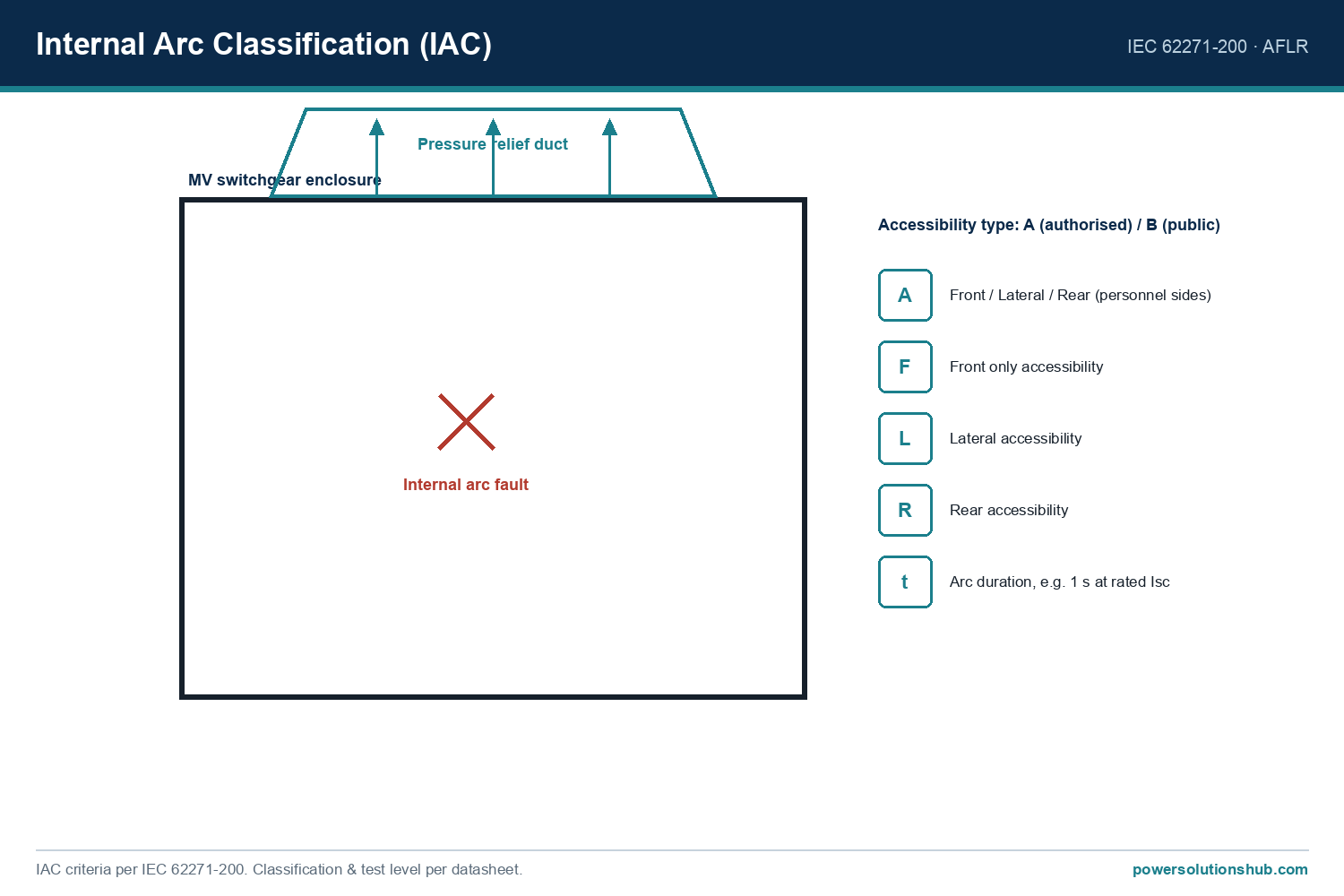
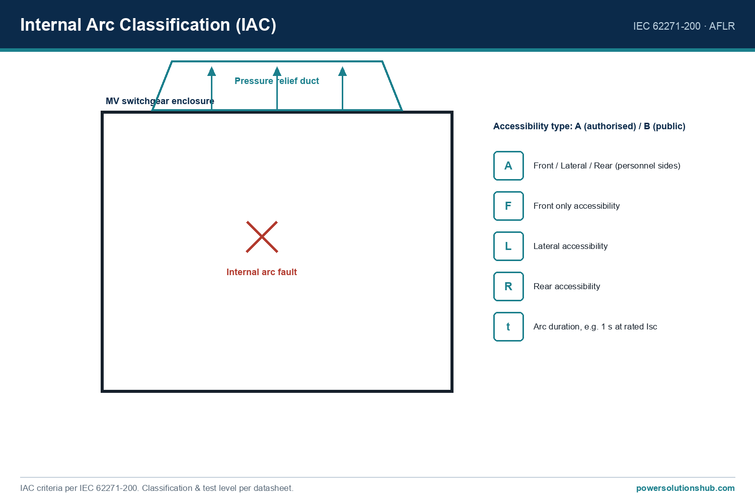
In addition to breaker breaking capacity, F400 enclosures are classified to withstand internal arcing at up to 31.5 kA for 1 second under the AFLR internal arc classification. An optional arc protection unit can detect an internal arc flash event and trip the feeding breaker automatically to limit fault energy.

Selection Criteria for F400 Cubicles

When specifying F400, buyers should evaluate:

  • Rated voltage class — 36 kV or 40.5 kV depending on network requirements.
  • Breaker technology — vacuum or SF6, selectable per project preference since both share the same cubicle and control interface.
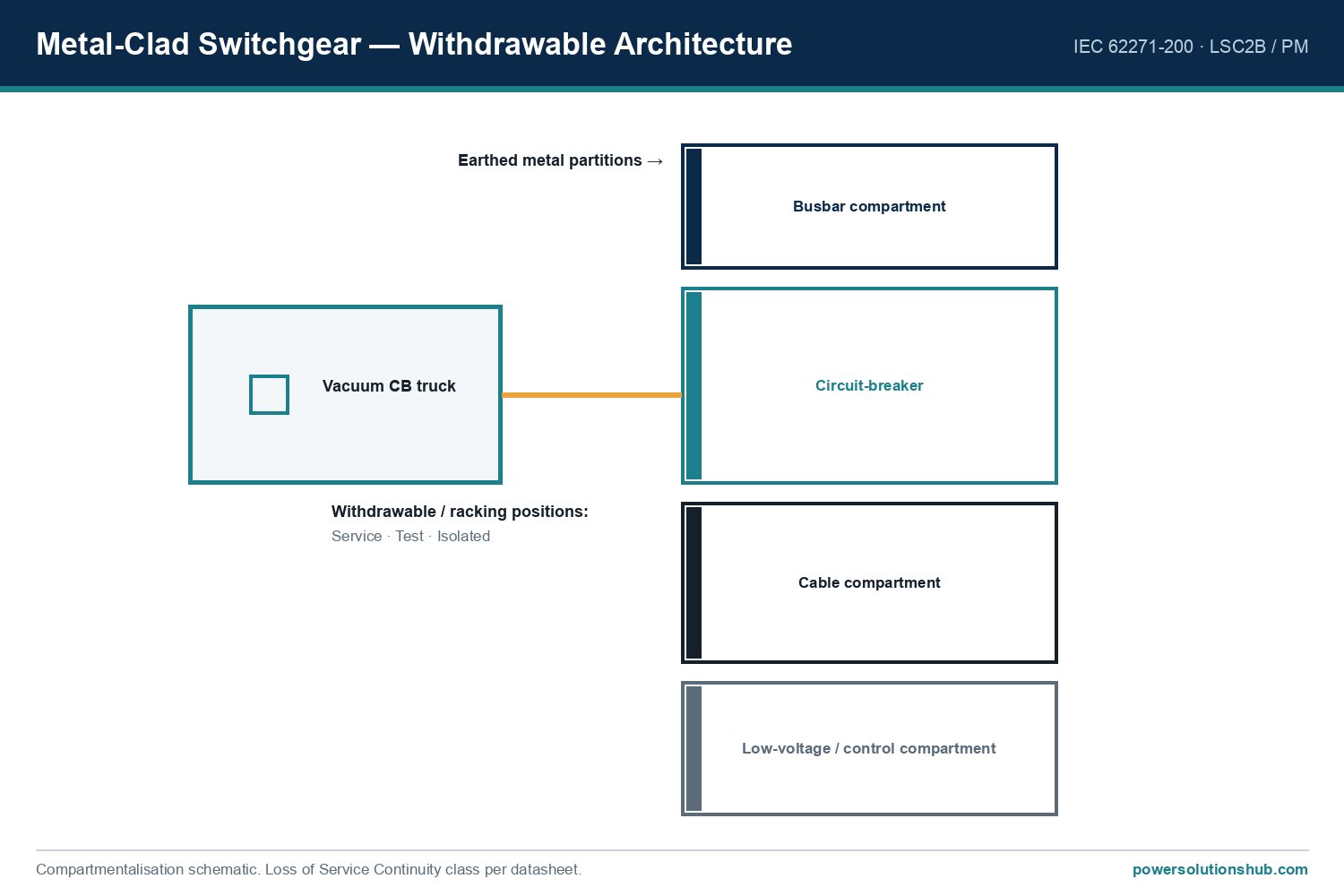
  • Internal arc protection level (LSC2B / AFLR) — F400 cubicles use earthed metallic partitions between MV compartments (LSC2B), isolating each compartment against electrical, mechanical and thermal fault effects.
  • Seismic requirement — F400 has certified seismic withstand of 1.25 g, suitable for regions with seismicity up to magnitude 8 on the Richter scale.
  • Footprint constraints — cubicle width from 900 mm, height from 2,255 mm (without VT) up to 2,335 mm (with VT), and depth of 2,724 mm (available with forced ventilation at 2500 A).
  • Digital integration needs — compatibility with EcoStruxure Grid/Power architecture, PowerMeter, Circuit Monitor, GemControl, and Easergy series protection relays for remote monitoring and control.
  • Maintenance interval expectations — F400 requires only routine operating checks, cleaning and greasing every 5 to 10 years, and is designed for a 30-year service life.

Safety and Operational Features

F400 emphasizes operator safety through several embedded design elements. All routine operations — opening, closing of circuit breaker and earthing switch — can be carried out remotely, keeping operators away from the cubicle front during switching. A single “anti-reflex” handle is used for all manual operations to reduce operator error. A Voltage Presence Indicator System (VPIS) on the front panel confirms the absence or presence of energy before the earthing switch is operated. Racking the withdrawable breaker in or out is only possible with the cubicle door closed, and mechanical/electrical interlocks are embedded throughout the range. The earthing switch is rated with making capacity, an important safety attribute for fault-closing scenarios.

Digital and Monitoring Ready Solutions

F400 is positioned as an EcoStruxure-ready switchgear platform, supporting connected sensors such as Easergy TH110 (thermal) and Easergy CL110 (environmental), arc sensors, and remote-controlled circuit breaker and earthing switch actuators, feeding into EcoStruxure Grid or EcoStruxure Power architectures for substation monitoring, asset advisory, and SCADA integration. Direct access to product documentation — catalogs, user guides, relay manuals — is available via QR codes printed on the front door of each cubicle.

Applications

F400 is applied across utility and industrial installations, including:

  • Power supply companies: HV/MV substations, MV/MV substations, MV/LV substations, and power generation facilities.
  • Industry: oil & gas, chemical, automotive, and mining/mineral/metal industries.
  • Infrastructure: airports, ports, and water treatment plants.
  • Seismic zones: certified for seismic environments up to magnitude 8 equivalent loading.

Standards and Compliance

F400 internal arc withstand performance is developed for all functional units to achieve the AFLR protection class in accordance with IEC/EN 62271-200. F400 is fully compliant with metal-enclosed switchgear IEC standards, and its seismic certification for 1.25 g references IEEE 693 (2018), IEC 60068-3-3, IEC 62271-210, and IEC 60068-2-6. Design, manufacturing and testing follow ISO 9001:2008 quality standard, with type testing performed for each performance level in the range.

What voltage range does F400 metal clad switchgear cover?

F400 covers medium-voltage power distribution from 1 kV up to 36/40.5 kV, making it suitable for HV/MV and MV/MV substation applications.

What is the difference between the SF1, SF2, and HVX breaker options?

SF1 and SF2 are rated at 36 kV with a rated short-circuit breaking current of 40 kA, while HVX is rated at 40.5 kV with a breaking current of 31.5 kA; all share the same 1250 A/2500 A current ratings and 25 kA short-time withstand rating.<!– 🔴 iddia: 36 kV,

Looking for F400 Metal Clad Switchgear?

Looking for high-quality f400 metal clad switchgear? We provide expert engineering support and reliable products for all your medium voltage needs.

For quotations and requests: info@electricistanbul.com

WhatsApp: +90 501 076 69 91
Schneider Premset Switchgear

Schneider Premset Switchgear

Premset switchgear (marketed by Schneider Electric under the “PremSet” name within its Set Series family) is a compact, modular medium-voltage switchgear line built around a Shielded Solid Insulation System (SSIS), in which every live part of the main circuit is encapsulated in an earthed epoxy or EPDM shield so the assembly is classified as “accidentally touchable.” This article covers the product’s design philosophy, technical ratings, functional variants, selection criteria, applications, and governing standards for engineering and procurement teams. It is particularly relevant for buyers and EPC contractors sourcing MV secondary distribution equipment across the Middle East and Gulf region including Egypt and Saudi Arabia, North Africa, CIS countries, and Sub-Saharan Africa, where compact footprint, tropicalized ratings, and long service life are recurring procurement priorities.

Schneider Premset Switchgear — schematic
Schneider Premset Switchgear — schematic.

What Is Premset Switchgear?

Premset is a 17.5 kV-class compact modular vacuum switchgear system positioned by Schneider Electric within its broader Set Series portfolio of MV and LV switchboards. The defining feature is the SSIS design: rather than relying solely on air or gas insulation with exposed conductors inside grounded enclosures, Premset embeds the switching, disconnecting, and earthing functions in solid, shielded insulation, reducing the probability of internal arc faults and enabling a smaller equipment footprint.

The system was previously known under the same “Premset” name and has been renamed “PremSet” as part of Schneider Electric’s Set Series naming consistency initiative, alongside other renamed products such as ComPact, MasterPact, TransferPact, and FuPact.

Selection reference
Selection reference.

Core Technology: Shielded Solid Insulation System (SSIS)

The SSIS concept is the technical backbone of the Premset range. The entire main circuit — switch-disconnectors, earthing switches, current and voltage sensors, and metering units — is insulated with solid epoxy or EPDM material whose outer surface is maintained at earth potential throughout. Because the electric field does not propagate into the surrounding air, the switchgear body itself becomes safe to approach or touch under normal operating conditions.

This design is stated by the manufacturer to align with the PA (accidentally touchable) classification defined in IEC 62271-201, the standard covering AC metal-enclosed and solid-insulation switchgear assemblies for rated voltages above 1 kV up to and including 52 kV.

Key benefits attributed to SSIS include: – Reduced sensitivity to harsh environments such as humidity, dust, and pollution – Lower risk of phase-to-phase faults due to solid insulation between phases – Extended service life expectancy compared to conventional air-insulated designs

SSIS is applied not only to the main switching device but also to auxiliary functions, including the M06S compact metering unit, current transformers, and voltage transformers.

The “3-in-1” Integrated Core Unit

Rather than using separate devices for breaking, disconnecting, and earthing, Premset integrates all three functions into a single core unit with only three defined positions:

  1. Closed — circuit connected
  2. Open and disconnected — circuit isolated
  3. Earthed — downstream conductors grounded

This single-line arrangement combines a switch-disconnector using vacuum interrupters with an earthing switch sealed in a tank at atmospheric air pressure, allowing MV cables to be earthed directly through the earthing switch without requiring any other device. The series arrangement of the two devices provides double isolation between busbars and cables.

Operators benefit from an intuitive mimic diagram with two clear position indicators, designed in accordance with IEC 62271-102, the standard governing high-voltage alternating-current disconnectors and earthing switches. All interlocks between the switching, disconnecting, and earthing functions are built-in as standard, positively driven, and keyless, applying equally to circuit breaker and load break switch variants.

Integrated Cable Test Feature

For maintenance teams, Premset includes a front-accessible cable test function implemented through dedicated earth rods, eliminating the need to enter the cable box, operate main switches, or dismantle cable terminations before testing. This cable test device is stated to meet the requirements of IEC 62271-200, the standard for AC metal-enclosed switchgear and controlgear for rated voltages above 1 kV and up to and including 52 kV.

Technical Ratings and Specifications

Premset is offered across three voltage classes, with insulation levels and short-circuit performance summarized below.

Parameter 7.2 kV 12 kV 17.5 kV
Rated voltage 7.2 kV 12 kV 17.5 kV
Power-frequency withstand voltage, 50–60 Hz, 1 min (rms) 20 kV 28 kV 38 kV
Lightning impulse withstand voltage, 1.2/50 µs (peak) 60 kV 75 kV 95 kV

Additional functional and environmental ratings:

Parameter Value
Ambient temperature range -25 °C to +45 °C
Humidity, 24 h 95%
Humidity, 1 month 90%
Vibration, 2–13.2 Hz (IEC 60068-2-6) 1 mm
Vibration, 13.2–100 Hz (IEC 60068-2-6) 0.7 g
Short-time withstand current, functional unit with circuit breaker (Ik max/tk) 25 kA / 3 s
Rated current, busbar (Ir max) 1250 A
Rated current, circuit breaker (Ir) 630 A / 1250 A

For marine-rated protection and control chains, Premset Marine supports short-circuit performance up to 25 kA for 1 second.

Design and Connection Features

Premset’s flexibility is built around a common architecture used across every configuration, which simplifies customization and installation:

  • Universal flat power connection — a patented single connection interface allowing cables to be routed from the front, rear, bottom, or top, while maintaining earth shield continuity.
  • Embedded sensors — integrated current and voltage sensors built around the core function, avoiding the need for extra or larger cubicles.
  • Standardized cabling height — all cable connections positioned at 700 mm to simplify installation across the range.
  • Multiple cable box dimensions — a range of sizes to suit different substation rooms and cabling arrangements, with an embedded voltage option.

These design choices are intended to reduce both installation time and total lifecycle footprint, which is a common evaluation criterion for utilities and industrial buyers standardizing on a single switchgear platform across multiple substations.

Digital and Smart Grid Capabilities

Premset architecture supports distributed intelligence through intelligent electronic devices (IEDs) that communicate over a standard protocol with plug-and-play configuration. Supported functions include:

  • Feeder automation with built-in local intelligence and communication
  • Load management through integrated smart metering
  • Asset management via advanced switchgear and transformer monitoring
  • Automatic transfer system (ATS) functionality to reduce power supply interruption

Connected components in the ecosystem include fault passage indicators, protection relays, energy quality monitoring devices, switch controllers, and substation monitoring devices, linked via radio, 2G/3G, or Ethernet communication networks.

Applications

Premset switchgear is designed for use across a broad range of MV secondary distribution scenarios, including:

Buildings and industry – MV/MV and MV/LV consumer substations (direct, double feeder, loop, radial connections) – MV/LV consumer substations with MV backup – MV private networks

Distribution networks – MV/MV switching substations – MV/LV distribution substations and ring main units – MV distributed generation

Marine applications Premset holds DNV-GL type approval certification for marine use, offering an enhanced protective environment, improved reliability, and a smaller footprint compared to conventional shipboard switchgear. The marine variant retains the electrical and dimensional characteristics of the standard range, adapted with features such as PM partition-class compartmentalization, front access, IP41 or IP32 enclosure ratings (IP67 for HV parts), and optional thermal diagnostics. A dedicated tunnel above the cubicle is designed to absorb gases from internal arcing events specific to onboard installations.

Environmental and Long-Term Reliability Considerations

Premset is offered as an SF6-free design, positioning the range for markets and end users seeking to reduce dependency on SF6 gas insulation in MV switchgear. Combined with the SSIS insulation approach and reduced number of operating steps (a single motion each for opening/disconnecting and for earthing), the range is positioned to lower total cost of ownership through extended service life and simplified maintenance intervals.

Standards and Compliance

Premset switchgear is engineered against multiple IEC standards relevant to MV switchgear procurement:

  • IEC 62271-200 — governing AC metal-enclosed switchgear and controlgear; referenced specifically for the integrated cable test device.
  • IEC 62271-201 — governing AC metal-enclosed and solid-insulation switchgear assemblies; referenced for the PA (accidentally touchable) classification of the SSIS design.
  • IEC 62271-102 — governing high-voltage AC disconnectors and earthing switches; referenced for the mimic diagram and position indication design.
  • IEC 60068-2-6 — governing vibration testing procedures; referenced for the stated vibration withstand values.

Buyers specifying MV switchgear for regulated utility or industrial projects should request certification documentation confirming compliance with the applicable standard for the specific function (switch-disconnector, circuit breaker, or metering unit) being procured.

Selection Criteria for Buyers

When evaluating Premset switchgear against alternative MV switchgear platforms, procurement and engineering teams should assess:

  1. Voltage class required — 7.2 kV, 12 kV, or 17.5 kV, matched to network nominal voltage and future expansion plans.
  2. Short-circuit and current ratings — confirm the 25 kA/3 s short-time withstand and busbar/circuit-breaker current ratings meet system fault-level and load requirements.
  3. Insulation philosophy — whether a solid, shielded insulation approach (as opposed to gas- or air-insulated designs) aligns with site environmental conditions (humidity, dust, pollution exposure).
  4. Environmental rating needs — ambient temperature range and humidity tolerance, particularly relevant for installations in high-humidity or high-temperature GEO markets.
  5. Digital integration requirements — whether feeder automation, remote monitoring, or automatic transfer system functionality is needed for the substation.
  6. Application type — standard MV/LV distribution substation, ring main unit, distributed generation interface, or marine/offshore installation requiring DNV-GL type-approved equipment.
  7. Cable connection layout — front, rear, bottom, or top cabling access based on civil works and substation room layout.

What does SSIS mean in Premset switchgear?

SSIS stands for Shielded Solid Insulation System. It refers to the design in which the entire main circuit is insulated with solid epoxy or EPDM material, and the outer surface of that insulation is held at earth potential, preventing the electric field from propagating into surrounding areas of the switchgear.

What voltage classes are available in the Premset range?

Premset switchgear is available in 7.2 kV, 12 kV, and 17.5 kV rated voltage classes, each with corresponding power-frequency and lightning impulse withstand voltage levels.

Is Premset switchgear SF6-free?

Yes. Premset is described as an SF6-free design, intended to free operators from environmental constraints associated with SF6 gas handling and disposal.

What is the short-circuit rating of Premset switchgear?

The functional unit with circuit breaker has a short-time withstand current rating of 25 kA for 3 seconds, with busbar current up to 1250 A and circuit breaker rated current of 630 A or 1250 A depending on configuration.

Can Premset switchgear be used in marine applications?

Yes. A dedicated Premset Marine version holds DNV-GL type approval certification and includes features such as PM partition-class compartments, front access, IP41/IP32 enclosure protection (IP67 for HV parts), and a gas-absorbing tunnel designed for internal arc events on board ships.

Which IEC standards apply to Premset switchgear?

Premset references several IEC standards depending on the function being evaluated, including IEC 62271-200 for the metal-enclosed switchgear cable test feature, IEC 62271-201 for the accidentally-touchable (PA class) solid insulation design, IEC 62271-102 for disconnector/earthing switch mimic diagram conventions, and IEC 60068-2-6 for vibration testing.

What is the “3-in-1” function in Premset switchgear?

The 3-in-1 core unit integrates breaking, disconnection, and earthing functions into a single device with three positions — closed, open and disconnected, and earthed — simplifying operation and reducing the number of separate devices needed per bay.

Looking for Premset Switchgear?

Looking for high-quality premset switchgear? We provide expert engineering support and reliable products for all your medium voltage needs.

For quotations and requests: info@electricistanbul.com

WhatsApp: +90 501 076 69 91
Schneider SM6-36 Air Insulated Medium Voltage Switchgear

Schneider SM6-36 Air Insulated Medium Voltage Switchgear

SM6-36 is a metal-enclosed, air insulated medium voltage switchgear range engineered for distribution networks up to 36 kV, combining SF6 or vacuum interrupting technology inside sealed-for-life switching poles with a modular cubicle architecture that allows incoming, outgoing, circuit-breaker, ring main unit, and metering functions to be assembled into a single harmonized line-up. This article covers the SM6-36 functional unit types, its key technical ratings, internal arc classification, selection criteria for utility and industrial substations, applicable IEC standards, and answers to the most common buyer questions. Power Solutions Hub supplies and supports SM6-36 switchgear across export markets including the Middle East and Gulf incl. Egypt and Saudi Arabia, North Africa, CIS, and Sub-Saharan Africa, where compact, low-maintenance MV switchgear is a standard requirement for grid and industrial substations.

SM6 — schematic
SM6 — schematic.

What Is SM6-36 Air Insulated Medium Voltage Switchgear?

SM6 is a modular medium voltage cubicle range built on more than forty years of Schneider Electric experience in protection, monitoring, and control solutions for MV networks, with the switching poles based on more than thirty years of SF6 interruption technology. The SM6-36 variant extends the harmonized SM6 platform up to 36 kV, allowing operators to combine multiple functional cubicles — incoming/outgoing feeders, circuit-breaker units, ring main units, and metering panels — to build a complete distribution substation. Globally, more than 1,700,000 SM6 cubicles have been installed worldwide , following an earlier milestone of over 1,500,000 units by 2015 , reflecting broad reference deployment across utility, industrial, and infrastructure projects.

Each SM6-36 cubicle is designed with switching and earthing parts housed inside a sealed-for-life SF6-filled unit for the operational life of the equipment , and the overall product range is rated for a 30-year service life . All cubicles are 100% factory tested and do not require on-site testing before commissioning , which shortens installation time for export projects where local test facilities may be limited.

Selection reference
Selection reference.

Functional Units and Variants Available in SM6-36

The SM6 platform is built around a common set of functional cubicle types, which can be combined to match the single-line diagram of the substation:

  • Ring main unit (RMU) cubicles — load-break switch disconnector functions for ring or radial distribution feeders.
  • Circuit-breaker cubicles — withdrawable or fixed circuit-breaker units for protected incoming/outgoing feeders and transformer protection.
  • Metering cubicles — voltage/current transformer compartments for revenue or protection metering.
  • Bus coupler and bus riser cubicles — for busbar sectionalizing and extension between switchboard sections.
  • Fuse-combination cubicles — combined switch-fuse protection for transformer feeders where fuse-based protection is preferred over a circuit breaker.

At 36 kV, switching devices are based on the SF1 circuit-breaker range; the Evolis vacuum circuit breaker is not available at 36 kV and is used only on lower-voltage SM6 cubicles . Rated current for the switching devices is available at 630 A and 1250 A, with associated rated short-circuit breaking currents of 16 kA and 25 kA , giving buyers a choice of breaker duty depending on the transformer or feeder load to be protected.

Technical Specifications and IAC Comparison Table

The table below summarizes the key numeric ratings for SM6-36, alongside the SM6-24 variant from the same harmonized platform, to help specifiers compare internal arc classification (IAC) and voltage class options when selecting the correct cubicle family.

Parameter SM6-24 SM6-36
Maximum rated voltage 24 kV 36 kV
Rated current (switching devices) 630 A / 1250 A 630 A / 1250 A
Rated short-circuit breaking current 16 kA / 25 kA 16 kA / 25 kA
Internal arc classification, 3-sided (IAC: A-FL) 12.5 kA 1s, 16 kA 1s, 20 kA 1s 16 kA 1s
Internal arc classification, 4-sided (IAC: A-FLR) 12.5 kA 1s, 16 kA 1s, 20 kA 1s Available (per specific configuration)
Breaker technology SF1 / Evolis vacuum SF1 (Evolis not available at 36 kV)
Service life 30 years 30 years
Factory testing 100% factory tested 100% factory tested

Note that internal arc gas evacuation options differ between the two voltage classes: SM6-24 offers both downward and upward gas evacuation, while SM6-36 uses downward gas evacuation as the standard arrangement .

Internal Arc Protection and Operator Safety

Internal arc withstand is a decisive selection criterion for utilities and industrial plants where operator safety and continuity of service are critical. SM6-36 offers 3-sided internal arc protection classified IAC: A-FL at 16 kA for 1 second , meaning the enclosure is validated to contain and vent arc fault energy away from the front, sides, and rear-adjacent accessible zones, protecting personnel standing in front of the switchgear during an internal fault event. Beyond the enclosure rating, SM6 cubicles incorporate a three-position switch structure to prevent incorrect switching sequences, a fully closed earthing switch, positive-indication position indicators, internal arc withstand in cable and connection compartments, clear mimic diagrams, an anti-reflex operating lever, and physically segregated compartments — all standard mechanical and procedural safeguards built into the SM6 design philosophy.

Selection Criteria for SM6-36 Switchgear

When specifying SM6-36 for a project, buyers and consulting engineers should evaluate:

  • Rated voltage and insulation level — confirm the network’s nominal voltage falls within the SM6-36 envelope (up to 36 kV) rather than requiring the lower SM6-24 platform.
  • Rated current and short-circuit duty — match the 630 A/1250 A current rating and 16 kA/25 kA short-circuit breaking current to the transformer and feeder fault-level study for the substation.
  • Internal arc classification — verify whether 3-sided (A-FL) protection is sufficient, or whether the layout requires additional rear-side (A-FLR) considerations, and confirm the gas evacuation routing (downward) fits the substation civil design.
  • Functional unit mix — determine which combination of ring main unit, circuit-breaker, metering, and bus coupler cubicles matches the required single-line diagram.
  • Monitoring and connectivity needs — SM6 cubicles are compatible with PowerMeter metering units, Easergy P3 and Easergy Sepam multifunction protection relays, and self-powered VIP protection relays, plus connectable sensors (SC110, CL110, TH110) for continuous asset condition monitoring; the Easergy TH110 conductor temperature sensor is fitted as standard on cable terminations of relevant cubicles .
  • Maintenance regime — factor in the reduced maintenance burden from sealed-for-life SF6 switching and earthing parts, versus operating mechanisms designed for lower maintenance frequency under normal service conditions.
  • End-of-life SF6 handling — plan for certified SF6 recovery and disposal procedures in line with local environmental regulation before decommissioning.

Applications

SM6-36 switchgear is applied in primary and secondary MV distribution substations, industrial plant intake switchrooms, transformer feeder protection, ring main distribution networks, and utility distribution feeders where a 36 kV insulation class is required. Reference installations spanning airports, universities, hospitals, cement plants, data centers, and government facilities across multiple regions demonstrate the platform’s applicability to both utility-grade and industrial-grade MV distribution projects, including installations referenced in Egypt and Saudi Arabia among other Middle East and Gulf, North Africa, CIS, and Sub-Saharan Africa markets.

Standards and Compliance

SM6 switchgear is designed in accordance with the IEC standard framework applicable to metal-enclosed medium voltage switchgear . End-of-life SF6 gas recovery is compliant with IEC 62271-4:2013 , and disposal must follow local environmental regulation, including Regulation (EU) No 517/2014 for European countries, given SF6’s classification as a powerful greenhouse gas requiring certified recovery rather than atmospheric release .

What is the maximum rated voltage of SM6-36 switchgear?

SM6-36 covers medium voltage distribution installation requirements up to 36 kV, extending the harmonized SM6 cubicle platform beyond the 24 kV SM6-24 range .

Is the Evolis circuit breaker available on SM6-36?

No. The Evolis vacuum circuit breaker is not available at 36 kV; SM6-36 switching devices use the SF1 circuit-breaker range instead .

Looking for SM6-36 Air Insulated Medium Voltage Switchgear?

Looking for high-quality sm6-36 air insulated medium voltage switchgear? We provide expert engineering support and reliable products for all your medium voltage needs.

For quotations and requests: info@electricistanbul.com

WhatsApp: +90 501 076 69 91
Schneider SM6-24 Air Insulated Medium Voltage Switchgear

Schneider SM6-24 Air Insulated Medium Voltage Switchgear

SM6-24 air insulated medium voltage switchgear is a metal-enclosed, modular 24 kV cubicle range from Schneider Electric that combines air-insulated busbars with sealed-for-life SF6 switching and earthing units to deliver compact, low-maintenance distribution and protection functions for primary and secondary substations. This article covers the SM6-24 cubicle family — its construction, functional variants (DM1, CM, PM, QM, GBC and related types), circuit-breaker and switch-fuse ratings, internal arc (IAC) classification, applicable IEC standards, and the selection criteria buyers need before specifying equipment for a project. It is written for engineers, EPC contractors, and utility procurement teams sourcing MV switchgear for the Middle East and Gulf region including Egypt and Saudi Arabia, North Africa, CIS countries, and Sub-Saharan Africa, where SM6 cubicles have an extensive installed reference base.

SM6 — schematic
SM6 — schematic.

What Is SM6-24 Air Insulated Switchgear?

SM6-24 belongs to Schneider Electric’s SM6 modular MV cubicle platform, which is manufactured with SF6 or vacuum switching technology and is designed for a 30-year service life. The switching and earthing parts sit inside a sealed-for-life SF6-filled unit, while the surrounding cubicle structure and busbar compartment use air as the primary insulation medium — hence the “air insulated” designation used in the manufacturer’s own catalogue naming for the SM6 range. This hybrid approach keeps the switching chamber maintenance-free while allowing straightforward busbar extension and connection work in the field.

Globally, Schneider Electric reports more than 1,700,000 SM6 cells installed worldwide, supported by over 2,500,000 SF6 medium voltage cells supplied by the company across its product history. The platform’s development timeline shows more than 300,000 SM6 cells in service by 1989 and over 1,500,000 by 2015, reflecting a mature, field-proven design rather than a recent introduction.

Selection reference
Selection reference.

Cubicle Types and Functional Variants

The SM6-24 range is built from functional units that can be combined side by side to build a complete switchboard. Key cubicle designations referenced in the manufacturer’s operating and maintenance documentation include:

  • DM1, DM1-W, DM1-Z — withdrawable circuit-breaker cubicles, where the circuit breaker can be racked out and racked in for isolation and maintenance.
  • DM2, DMV, DMVL — additional circuit-breaker and disconnector cubicle variants used for incoming/outgoing feeder and coupling functions.
  • CM, CM2, PM, QM, QMC, QMB, TM — fuse-combination and fused-switch cubicles for transformer protection, each with fuse-status indication and MV fuse replacement procedures defined in the manufacturer’s manual.
  • GBC-A, GBC-B — cubicles with dedicated fuse replacement procedures, typically used in ring/feeder configurations.
  • CVM — a metering/voltage variant included in the fuse-replacement instructions alongside CM/PM/QM types.

Each cubicle uses a three-position switch structure (open / closed / earthed) to prevent incorrect switching sequences, and the earthing switch has a full making capacity design, giving operators a mechanically interlocked, visually confirmed switching sequence.

High-Performance Breaking Devices

The SM6 range integrates SF1 and/or Evolis breaking devices, rated at 630 A and 1250 A, with breaking capacities of 16 kA and 25 kA. Note that the Evolis breaker option is not available at the 36 kV voltage level, meaning full breaker choice flexibility applies specifically to the SM6-24 platform.

Internal Arc (IAC) Classification

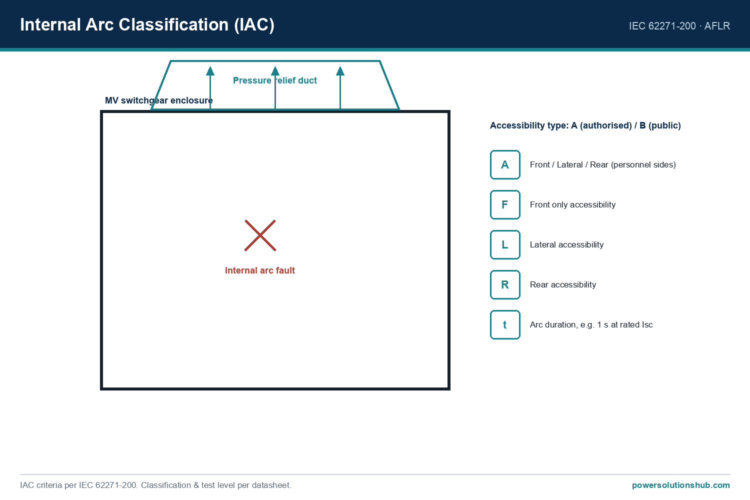
Internal arc withstand is a critical safety differentiator for MV switchgear specifiers. The SM6 range offers both 3-sided and 4-sided internal arc protection:

  • IAC: A-FL (3-sided arc protection) — for SM6-24, rated at 12.5 kA 1s, 16 kA 1s, and 20 kA 1s; for SM6-36, rated at 16 kA 1s.
  • IAC: A-FLR (4-sided arc protection) — for SM6-24, rated at 12.5 kA 1s, 16 kA 1s, and 20 kA 1s.

Gas evacuation can be routed downward for all units, or upward specifically for SM6-24 cubicles, giving substation designers flexibility for cable basements versus overhead exhaust ducting.

Selection Criteria for Buyers

When specifying SM6-24 air insulated medium voltage switchgear, evaluate the following:

  1. Rated short-time withstand / IAC class needed — determine whether 12.5 kA, 16 kA, or 20 kA 1s arc withstand is required based on upstream fault level and personnel safety requirements (3-sided vs. 4-sided protection).
  2. Breaking device type — confirm whether SF1 or Evolis vacuum circuit breakers suit the application, and required current rating (630 A or 1250 A) and breaking capacity (16 kA or 25 kA).
  3. Functional unit mix — select DM1/DM2/DMV/DMVL for circuit-breaker feeders, CM/PM/QM/QMC/TM/GBC types for fused transformer protection.
  4. Withdrawable vs. fixed design — DM1-W and DM1-Z variants allow the circuit breaker to be racked out for maintenance without de-energizing the entire busbar.
  5. Monitoring and connectivity — compatibility with PowerMeter, Easergy P3/Sepam protection relays, VIP self-powered protection relays, and Easergy TH110 temperature sensors for condition-based maintenance.
  6. Gas evacuation routing — downward or upward exhaust depending on switchroom layout.
  7. End-of-life compliance — dismantling and SF6 gas recovery service aligned with IEC 62271-4:2013.

Spec Comparison Table

Parameter SM6-24 SM6-36
Internal arc class, 3-sided (IAC A-FL) 12.5 kA 1s / 16 kA 1s / 20 kA 1s 16 kA 1s
Internal arc class, 4-sided (IAC A-FLR) 12.5 kA 1s / 16 kA 1s / 20 kA 1s Not specified in source
Breaking device rated current 630 A / 1250 A 630 A / 1250 A (SF1 only, Evolis unavailable)
Breaking capacity 16 kA / 25 kA 16 kA / 25 kA (where SF1 applicable)
Gas evacuation routing Downward or upward Downward only
Design service life 30 years 30 years

Applications

SM6-24 cubicles are used in primary and secondary distribution substations, industrial plants, data centers, airports, and utility ring main points where compact, low-maintenance MV switching combined with fused transformer protection is required. Reference installations documented by the manufacturer span airports, hospitals, universities, cement plants, and utility distribution companies across multiple regions, including projects in Egypt and Saudi Arabia. This global reference base supports specification confidence for new-build and retrofit projects in the Middle East and Gulf region including Egypt and Saudi Arabia, North Africa, CIS markets, and Sub-Saharan Africa.

Standards Compliance

SM6-24 cubicles are designed in accordance with IEC standards applicable to metal-enclosed MV switchgear with vacuum circuit breakers up to 24 kV. End-of-life dismantling and SF6 gas recovery follow IEC 62271-4:2013, alongside applicable local regulations such as EU Regulation No 517/2014 on fluorinated greenhouse gases. Because the switching units contain SF6 — a potent greenhouse gas — recovery, reclamation, or destruction of the gas is mandatory prior to disposal, and dismantling must only be performed by certified personnel.

Is SM6-24 truly “air insulated,” given that it uses SF6 gas?

The manufacturer’s own catalogue naming describes the SM6 range as metal-enclosed, air-insulated cubicles, referring to the busbar and general cubicle insulation medium. The circuit-breaker and earthing switch mechanism, however, is a separate sealed-for-life SF6-filled unit, which is standard practice for this hybrid design category.

What is the maximum internal arc withstand rating available for SM6-24?

SM6-24 offers internal arc classifications up to 20 kA for 1 second, available in both 3-sided (IAC A-FL) and 4-sided (IAC A-FLR) configurations.

Which circuit breakers are used in SM6-24 cubicles?

SM6-24 integrates SF1 and/or Evolis vacuum circuit breakers, rated at 630 A or 1250 A with breaking capacities of 16 kA or 25 kA.

Can the circuit breaker be withdrawn for maintenance without shutting down the busbar?

Yes. DM1-W and DM1-Z cubicle variants are specifically designed for racking the circuit breaker out and back in, allowing maintenance without full switchboard de-energization.

What is the expected service life of SM6-24 switchgear?

The SM6 modular platform, including the SM6-24 range, is designed for a 30-year service life under normal operating conditions.

How is the equipment disposed of at end of life?

Because the switching units contain SF6 gas, disposal requires certified recovery of the gas prior to dismantling, in compliance with IEC 62271-4:2013 and applicable regional F-gas regulations such as EU Regulation No 517/2014.

Does SM6-24 support remote monitoring and digital connectivity?

Yes. SM6-24 cubicles are compatible with PowerMeter metering units, Easergy P3 and Sepam multifunction protection relays, self-powered VIP protection relays, and Easergy TH110 conductor temperature sensors, which are factory-fitted as standard on cable terminations of relevant cubicles.

Looking for SM6-24 Air Insulated Medium Voltage Switchgear?

Looking for high-quality sm6-24 air insulated medium voltage switchgear? We provide expert engineering support and reliable products for all your medium voltage needs.

For quotations and requests: info@electricistanbul.com

WhatsApp: +90 501 076 69 91
Air-insulated medium-voltage switchgear — panel line-up for MV distribution

Air-Insulated Switchgear (AIS) — Types, Selection & Specifications

Air-insulated switchgear (AIS) is medium-voltage switchgear in which the busbars and main current-carrying parts are insulated by air, rated for systems above 1 kV up to about 40.5 kV and built to IEC 62271-200. It is the most widely used MV switchgear type, spanning compact secondary-distribution cubicles up to large withdrawable primary panels, and — because it uses air — it is inherently SF6-free in its insulation.

This pillar guide explains what air insulation means, how AIS spans the network from secondary cubicles to primary metal-clad, how it compares with gas-insulated switchgear, the product families we supply, the key ratings, the SF6-free picture, and how to select — for MV distribution and industrial projects across the Middle East and Gulf (including Egypt and Saudi Arabia), as well as North Africa, CIS and Sub-Saharan Africa.

What “air-insulated” means

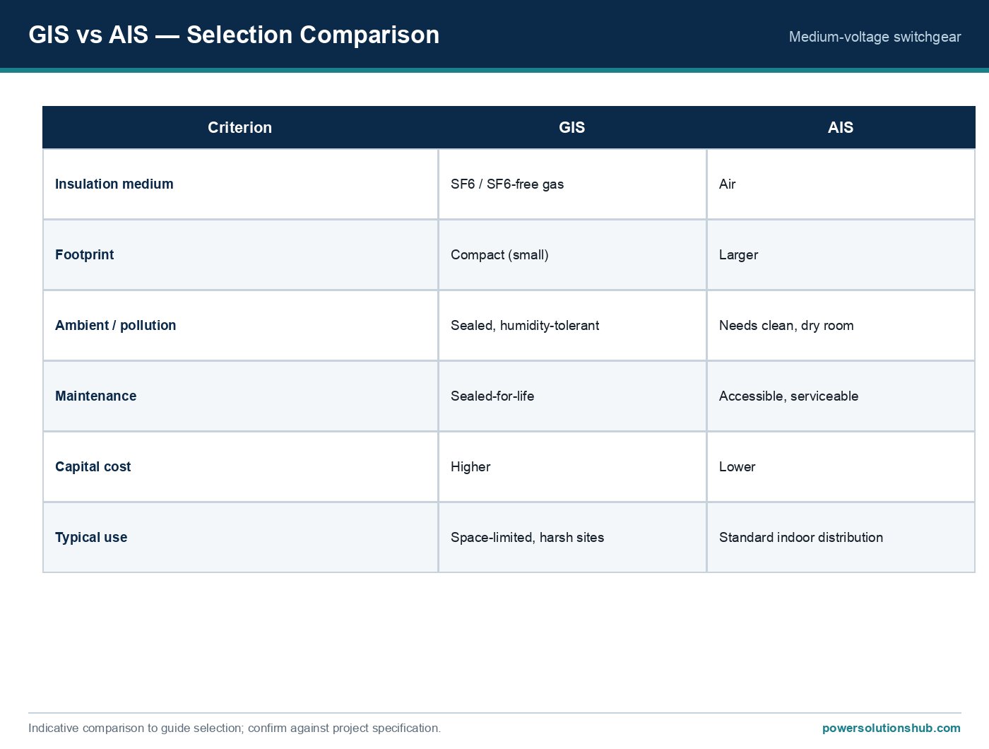
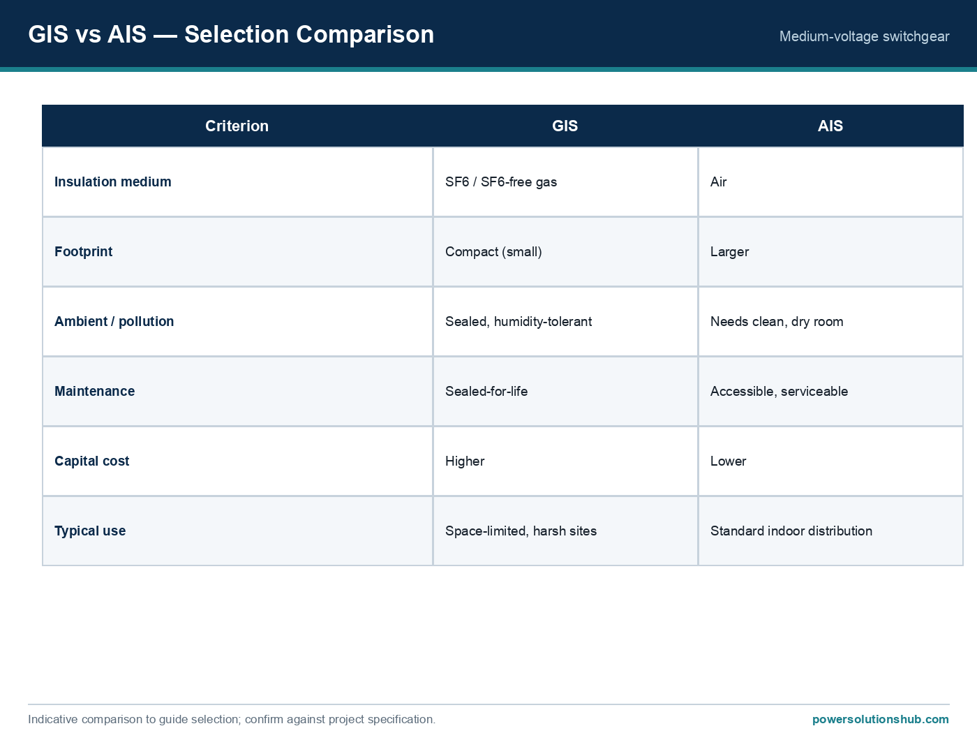
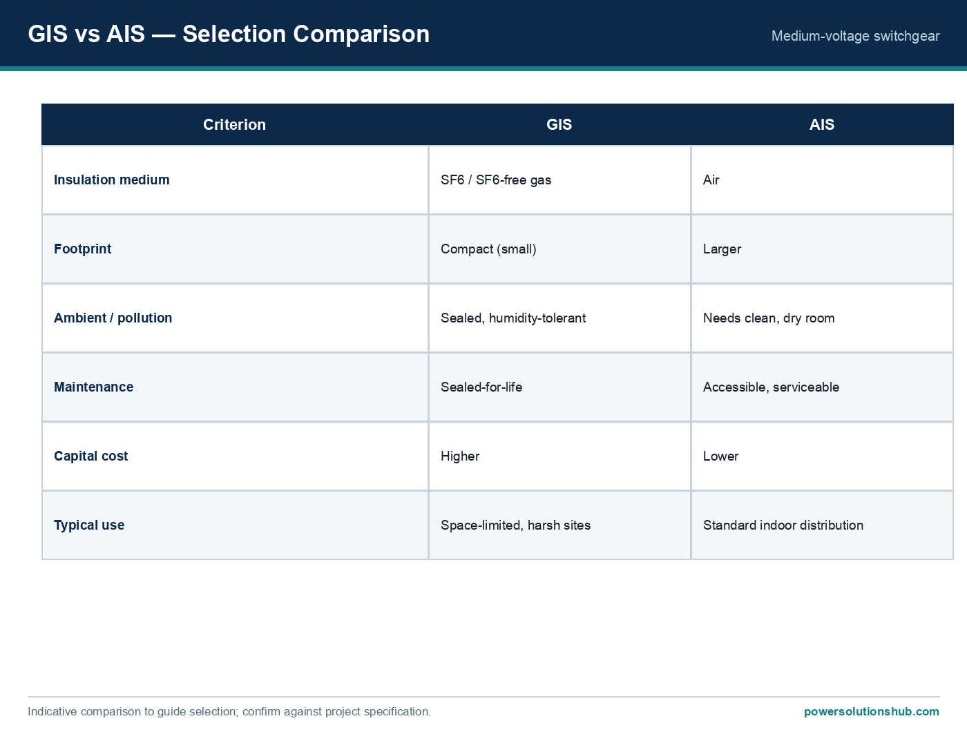
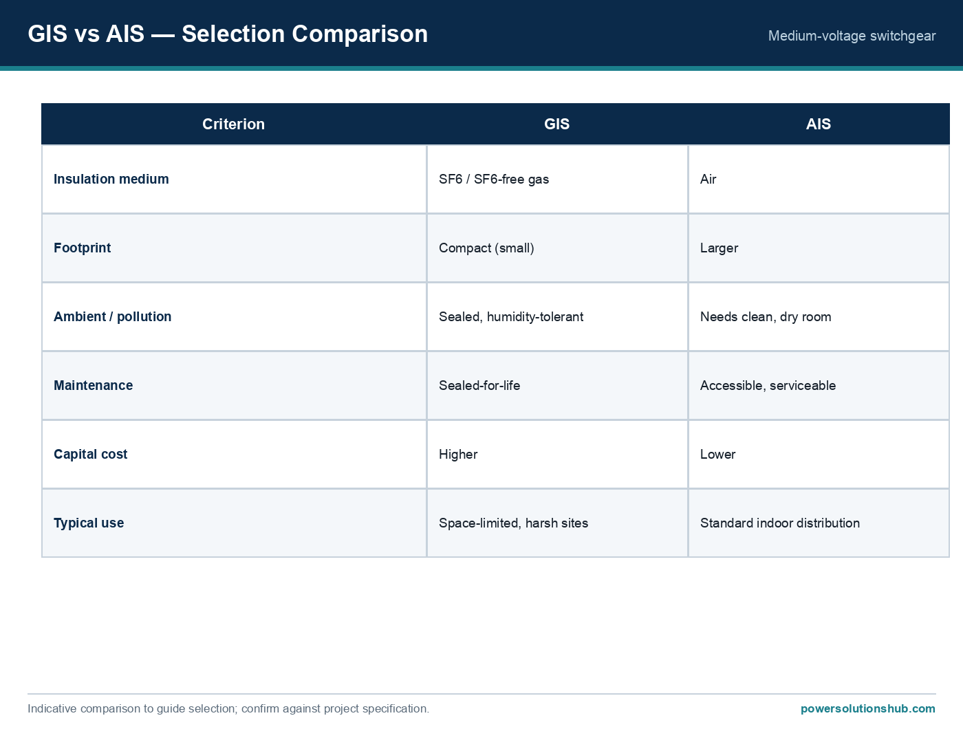
In an air-insulated panel the dielectric between live parts, and between live parts and earth, is air at atmospheric pressure. Because air has a lower dielectric strength than insulating gas, AIS needs larger phase-to-phase and phase-to-earth clearances — for a 36 kV system the minimum busbar air clearance is typically 35–36 cm — which makes an AIS panel physically larger than an equivalent gas-insulated one. In return, AIS is lower in capital cost, easy to inspect visually, straightforward to maintain, and needs no gas handling. The arc interruption itself is normally done by a vacuum interrupter inside the panel; it is the standing insulation that is air.

“Air-insulated” describes the insulation medium, not the construction. An AIS panel can be a simple secondary-distribution cubicle or a fully compartmented, withdrawable metal-clad primary panel — both are air-insulated. See the medium voltage switchgear pillar for the full insulation-vs-construction picture.

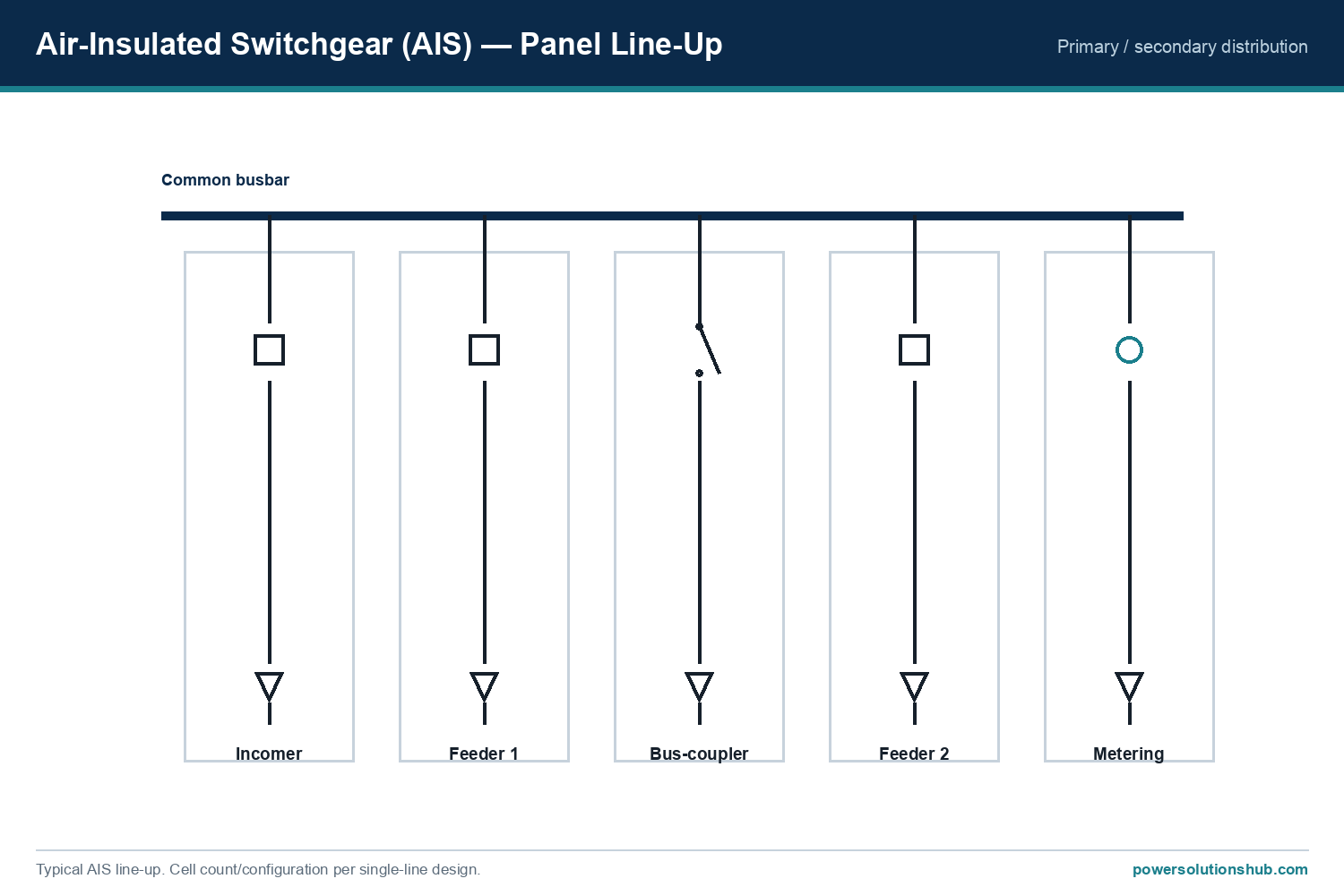
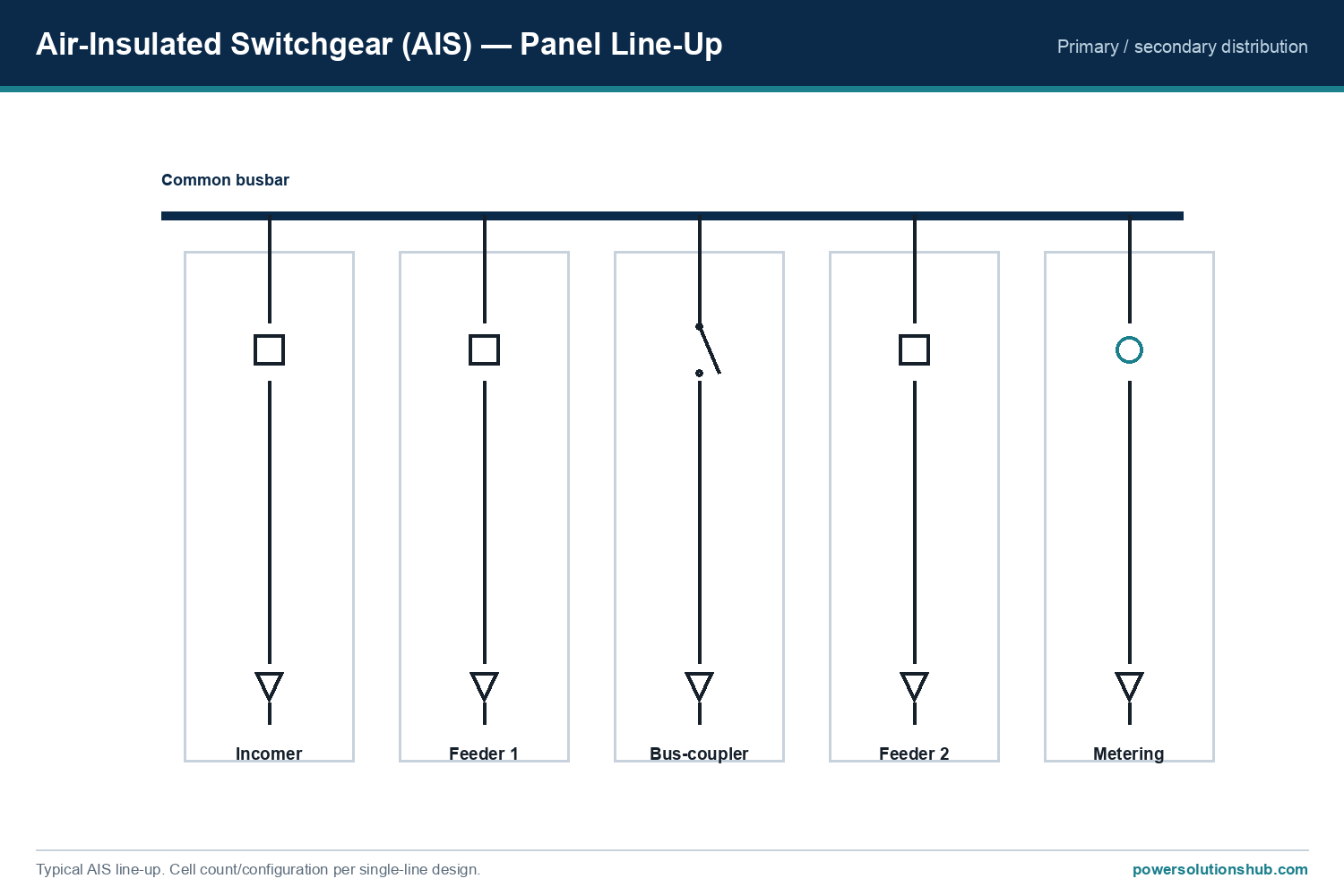
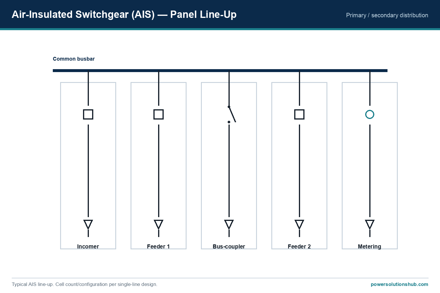
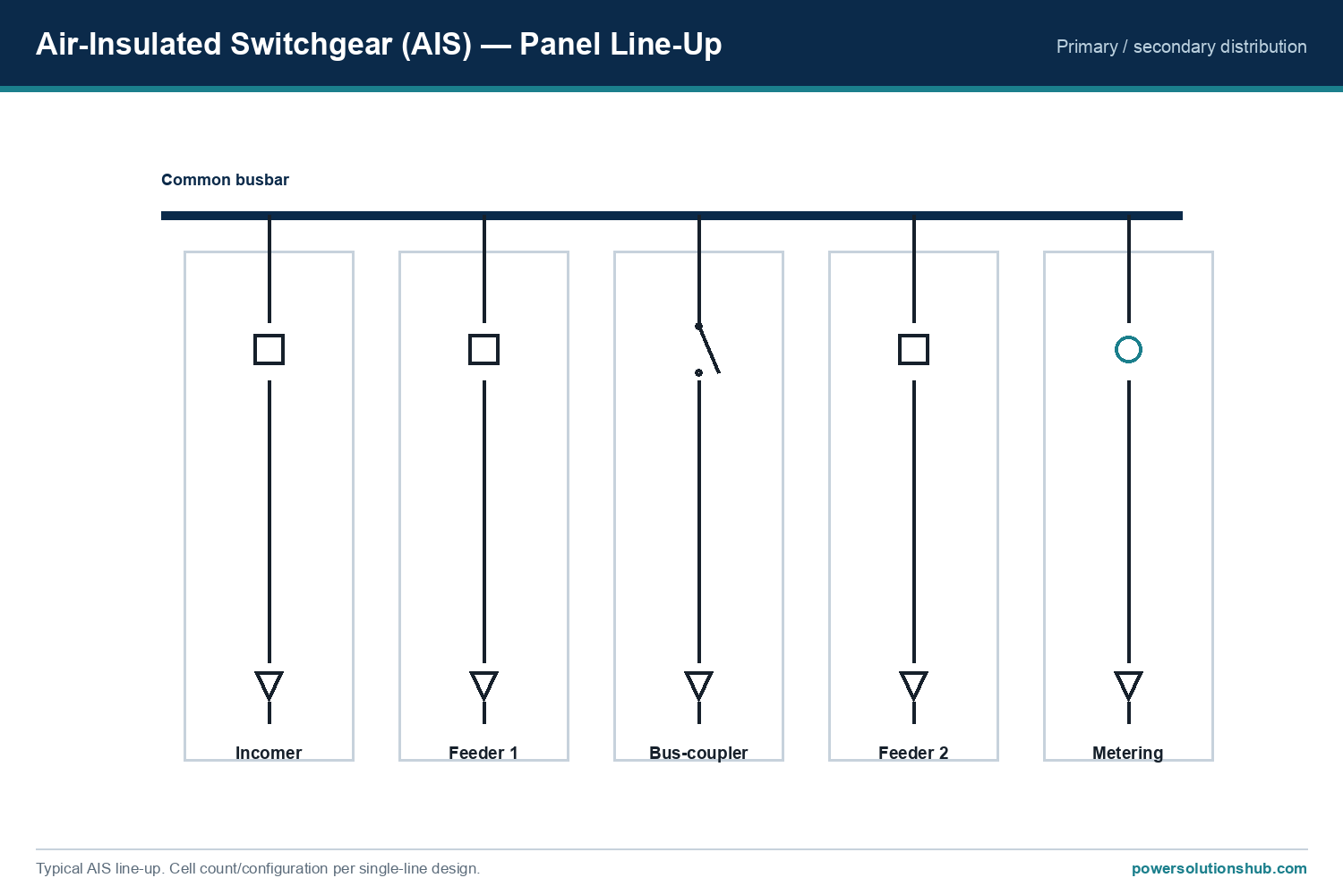
Air-insulated switchgear panel line-up — incomer, feeders, bus-coupler and metering
A typical AIS line-up: incomer, feeders, bus-coupler and metering panels sharing a common air-insulated busbar.

AIS across the network

Air insulation is used at every level of MV distribution, in two broad construction formats:

  • Secondary-distribution cubicles. Compact, modular, often fixed-mounted air-insulated panels for the many small MV/LV substations — for example Schneider SM6 (12–36 kV modular cubicles) and ABB UniSec (up to 24 kV, 1250 A, 25 kA). These provide incomer, feeder, transformer-protection and bus-coupler functions in an air-insulated, serviceable format.
  • Primary metal-clad panels. For high busbar current and fault level, the air-insulated panel takes the withdrawable, compartmented metal-clad form (ABB UniGear ZS1 up to 24 kV, 4000 A, 63 kA). The construction detail is covered in the metal-clad switchgear pillar.

So AIS and metal-clad are not alternatives on the same axis: metal-clad is one (primary, withdrawable) construction of air-insulated switchgear.

Functional units in an AIS line-up

An air-insulated switchboard is assembled from standard functional panels sharing a common busbar, so the single-line matches the installation. The usual functions are:

  • Incomer panel — brings the supply into the switchboard, usually with a circuit breaker and protection.
  • Feeder panels — the outgoing circuits to transformers, motors or sub-boards, each with its own breaker or switch and protection.
  • Bus-coupler / bus-section panel — links two busbar sections, allowing the board to be split or joined for maintenance and redundancy.
  • Transformer-protection panel — protects a distribution transformer, by a switch-fuse combination for smaller ratings or a circuit breaker with a relay for larger ones.
  • Metering panel — houses the current and voltage transformers for measurement and revenue metering.

Because the panels are modular, a board can be extended later by adding units to the busbar — one of the practical advantages of air-insulated construction. This modularity, and the ability to see and inspect the equipment directly, is a large part of why AIS remains the most common MV switchgear worldwide.

Construction formats and solid insulation

Air-insulated switchgear comes in more than one construction:

  • Fixed-mounted cubicles — the breaker or switch is built into the panel; simple and compact, typical of secondary distribution (e.g. Schneider SM6, ABB UniSec).
  • Withdrawable metal-clad — the compartmented, draw-out primary format (see the metal-clad switchgear pillar).
  • Shielded solid-insulation systems — some compact modular families, such as Schneider Premset (up to 17.5 kV), combine air insulation with shielded solid-insulated components and vacuum interruption, shrinking the footprint while keeping the serviceability of an air system.

The right format depends on the network level, the available space and the maintenance strategy — the same trade-offs that run through the whole medium voltage switchgear family.

AIS vs GIS — how to choose

The core selection question is insulation medium: air-insulated (AIS) or gas-insulated (GIS).

GIS vs AIS selection comparison — insulation, footprint, environment, maintenance and cost
Indicative AIS-vs-GIS comparison to guide selection; confirm against the project specification.
Criterion Air-insulated (AIS) Gas-insulated (GIS)
Insulation medium Air SF6 or SF6-free gas, sealed tank
Footprint Larger (needs clearances) Compact
Ambient / pollution Needs a clean, dry, controlled room Sealed, humidity- and pollution-tolerant
Maintenance Accessible, serviceable Sealed-for-life, minimal
Capital cost Lower Higher
Typical use Standard indoor distribution, primary metal-clad Space-limited, hot or harsh sites

AIS is the default where space and a controlled indoor environment are available and where low capital cost and easy servicing matter. GIS wins where the site is space-limited, hot, dusty or humid.

Air-insulated product families

The AIS families we most often supply:

Family Type Rated voltage Rated current Notes
Schneider SM6 Secondary cubicle 12 / 24 / 36 kV up to 630 A Modular; internal arc 12.5 / 16 / 20 kA 1 s
ABB UniSec Secondary up to 24 kV up to 1250 A 25 kA; SF6-free (UniSec Air) option
ABB UniGear ZS1 Primary metal-clad up to 24 kV up to 4000 A 63 kA; withdrawable, LSC2B
Schneider Premset Compact modular up to 17.5 kV Compact modular vacuum switchgear

SF6-free and air insulation

Because AIS uses air as its insulation, its busbar and main insulation are inherently SF6-free. The remaining question is the interrupter: modern AIS uses vacuum interruption, so a fully SF6-free air-insulated panel is readily available. Families such as ABB UniSec Air are explicitly SF6-free, compliant with the EU F-gas Regulation (EU 2024/573), with a global warming potential of 0. Where a project mandates SF6-free equipment, air-insulated switchgear with vacuum interruption is a natural fit. See the gas-insulated switchgear pillar for the SF6-free gas alternatives.

Key ratings to specify

Confirm these against the manufacturer’s datasheet for your configuration:

Parameter Typical AIS range
Rated voltage Ur 12 / 24 / 36 kV (up to 40.5 kV)
Rated normal current up to 1250 A (secondary); up to 4000 A (primary metal-clad)
Short-circuit breaking capacity up to 25 kA (secondary); up to 63 kA (primary)
Internal-arc withstand e.g. 12.5 / 16 / 20 kA for 1 s (secondary)
Insulation Air (SF6-free); vacuum interruption
Standard IEC 62271-200

How to choose

  1. Space and environment. AIS suits installations with room for clearances and a clean, dry, controlled environment; for space-limited or harsh sites choose GIS.
  2. Network level. Secondary distribution uses compact air-insulated cubicles (SM6, UniSec); primary distribution uses withdrawable metal-clad AIS.
  3. Cost and maintenance. AIS has a lower capital cost and is easy to inspect and service.
  4. SF6-free requirement. Air insulation with vacuum interruption is inherently SF6-free; confirm the family (e.g. UniSec Air) if the project mandates it.
  5. Maintenance strategy. If a local team will inspect and service the equipment directly, the accessible, repairable air-insulated design suits that model; if minimal-maintenance, sealed operation is preferred, weigh a gas-insulated alternative.
  6. Fault level and current. Match the short-circuit rating (up to 25 kA secondary, up to 63 kA primary) and the rated current to the network; high-current primary duty points to withdrawable metal-clad.

Standards

Air-insulated switchgear is governed by IEC 62271-200 (AC metal-enclosed switchgear 1 kV–52 kV), with the switching devices following the matching parts of the IEC 62271 series (-100 circuit-breakers, -102 disconnectors, -103 switches). Compact secondary substations may also be type-tested to IEC 62271-202.

Maintenance and inspection advantages

One of the enduring reasons AIS remains the most common MV switchgear is serviceability. Because the insulation is air, the live parts and connections are — with the panel safely isolated and earthed — directly accessible for visual inspection, cleaning, thermographic checks and component replacement. There is no sealed gas system to monitor or handle at end of life, and spare parts and repairs are straightforward. This makes AIS attractive where a local maintenance team looks after the installation and where the total cost of ownership favours a serviceable, repairable design over a sealed one. The trade-off is that this accessibility depends on keeping the switch room clean and dry, which in turn drives the environmental requirements below.

Air-insulated switchgear in hot and dusty climates

Because AIS relies on air clearances, the installation environment matters more than for a sealed panel. In Gulf, North-African and CIS projects, two points are decisive. First, ambient temperature: the rated current derates as the switch-room temperature rises, so the busbar and feeder ratings must be confirmed against the actual ambient — often meaning air-conditioning or a higher-rated busbar. Second, cleanliness and humidity: dust, salt and condensation can reduce the effective air insulation and cause tracking, so AIS switch rooms are kept filtered, dry and, where needed, climate-controlled. Where those conditions are difficult or expensive to maintain — a compact plot, a harsh outdoor-adjacent site, high pollution — a sealed gas-insulated panel is often the better long-term choice. Matching the switchgear type to the real site conditions is exactly the selection judgement this guide is built to support.

Applications

Air-insulated switchgear is used across MV distribution: secondary MV/LV substations, industrial plants, commercial buildings and infrastructure (compact cubicles), and the primary incoming substations of large facilities (metal-clad). Typical sectors include utilities and distribution networks, manufacturing and process industry, renewable energy plants (wind and solar collector substations), commercial and public buildings, water and infrastructure, and mining and oil & gas. It is the default MV switchgear where space and a controlled environment allow, and where low capital cost and easy maintenance are priorities — which is why it remains the most widely installed MV switchgear worldwide, complemented by gas-insulated panels where space or environment demand a sealed solution.

What is air-insulated switchgear (AIS)?

AIS is MV switchgear whose busbars and main current-carrying parts are insulated by air, built to IEC 62271-200; it spans compact secondary cubicles up to large withdrawable metal-clad primary panels and is inherently SF6-free in its insulation.

What is the difference between AIS and GIS?

AIS insulates with air and needs a larger, clean, dry room but is lower cost and serviceable; GIS encloses the live parts in a sealed gas tank, so it is compact, sealed-for-life and tolerant of humidity and pollution at a higher capital cost.

Is metal-clad switchgear the same as AIS?

Metal-clad is one construction of air-insulated switchgear (compartmented, withdrawable, primary distribution). All metal-clad is air-insulated, but not all AIS is metal-clad — secondary cubicles are AIS too.

Is air-insulated switchgear SF6-free?

Its insulation (air) is inherently SF6-free, and modern AIS uses vacuum interruption, so fully SF6-free families such as ABB UniSec Air are available, compliant with the EU F-gas Regulation with a GWP of 0.

What voltage and current does AIS cover?

AIS covers 12 to 36 kV (up to 40.5 kV), with currents up to about 1250 A in secondary cubicles and up to 4000 A in primary metal-clad panels, and short-circuit ratings up to 63 kA.

When should I choose AIS over GIS?

Choose AIS when space and a clean, dry, controlled indoor environment are available and low capital cost and easy servicing matter; choose GIS for space-limited, hot, dusty or humid sites.

Can an air-insulated switchboard be extended later?

Yes. AIS panels share a common busbar, so additional functional panels (feeders, couplers) can be added at the end of the line-up as the installation grows, subject to the busbar rating and available space — one of the practical advantages of air-insulated construction.

Does AIS need a special room?

AIS relies on air clearances, so the switch room should be kept clean, dry and, in hot climates, temperature-controlled; dust, humidity and high ambient temperature must be managed to preserve the insulation and the rated current.

Looking for Air-Insulated Switchgear (AIS)?

Looking for high-quality air-insulated medium voltage switchgear — secondary cubicles or primary metal-clad panels from leading brands? We provide expert engineering support and reliable products for all your medium voltage needs.

For quotations and requests: info@electricistanbul.com

WhatsApp: +90 501 076 69 91
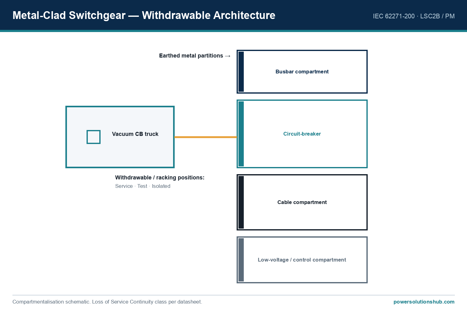
Metal-clad medium-voltage switchgear — withdrawable compartmented panels for primary distribution

Metal-Clad Switchgear — Withdrawable Architecture, Types & Selection

Metal-clad switchgear is a construction class of medium-voltage switchgear defined by IEC 62271-200, in which the main components — the withdrawable circuit breaker, the busbars and the cable connections — sit in separate compartments divided by earthed metal partitions, with the breaker mounted on a withdrawable (draw-out) truck. It is the standard format for primary distribution switchgear, and it is almost always air-insulated.

This pillar guide explains what “metal-clad” means, the withdrawable architecture and its service positions, the loss-of-service-continuity and partition classes, the main product families we supply, the key ratings, and how to select a panel — for MV distribution and industrial projects across the Middle East and Gulf (including Egypt and Saudi Arabia), as well as North Africa, CIS and Sub-Saharan Africa.

What “metal-clad” means

Metal-clad is a construction format, not an insulation medium — a distinction that matters (see the medium voltage switchgear pillar for the full insulation-vs-construction picture). A metal-clad panel is characterised by three things:

  • Separate, earthed metal compartments for the busbar, the circuit breaker and the cables, so a fault or maintenance in one compartment is contained and does not expose the others.
  • A withdrawable circuit breaker on a truck that can be racked in and out.
  • Metal partitions (PM) between compartments that are earthed, giving a high level of operator safety.

This is distinct from a simpler metal-enclosed cubicle (where the parts are in one enclosure) and from a compact, sealed ring main unit. Metal-clad is the format chosen where high busbar current, high fault levels and maximum continuity of supply are required — typically the incoming substation of a large facility.

Metal-clad withdrawable architecture — busbar, breaker and cable compartments with earthed partitions
Metal-clad construction: separate earthed compartments for busbar, withdrawable breaker and cables; the breaker truck racks between service, test and isolated positions.

The withdrawable architecture

The defining feature of metal-clad switchgear is the withdrawable (draw-out) circuit breaker. The breaker sits on a truck that can be moved between three positions:

  • Service — the breaker is fully engaged with the main and earthing contacts; the circuit is live and operational.
  • Test — the breaker is disconnected from the main circuit but its control circuits are still connected, so it can be operated and tested safely without energising the primary circuit.
  • Isolated / withdrawn — the breaker is fully disconnected and can be racked out and removed for maintenance or replacement, while the busbar and cable compartments remain in their state.

This is what gives metal-clad its continuity of supply advantage: a faulty breaker can be swapped for a spare in minutes without shutting down the whole board. Automatic shutters cover the live contacts when the breaker is withdrawn, maintaining the earthed-barrier safety.

Inside a metal-clad panel: the four compartments

The compartmented construction is what defines metal-clad, so it is worth seeing what each compartment does:

  • Busbar compartment — carries the main three-phase busbars that run along the switchboard connecting all the panels. Isolated behind an earthed metal partition, it can stay energised while work is done on the breaker.
  • Circuit-breaker compartment — houses the withdrawable breaker truck. This is the compartment that is opened for maintenance; the automatic shutters close over the live busbar and cable contacts as the truck is withdrawn.
  • Cable compartment — where the MV power cables terminate, often with the current transformers and earthing switch. Separated from the breaker so cables can be worked on safely.
  • Low-voltage (control) compartment — carries the protection relay, metering, control wiring and communications, physically separated from all the MV compartments.

Because these four zones are individually enclosed in earthed metal, a fault or an operator action in one compartment cannot propagate to the others — the safety principle at the heart of metal-clad design.

Vacuum circuit breakers and arc-resistant design

The switching device in a modern metal-clad panel is a withdrawable vacuum circuit breaker: the arc is interrupted in a sealed vacuum interrupter, which is compact, maintenance-light and has a long electrical life. The breaker truck’s racking mechanism, interlocks and shutters are all engineered so that the breaker can only be moved between service, test and isolated positions in a safe sequence — for example, it cannot be racked in or out while closed.

Metal-clad panels are also designed to be arc-resistant: if an internal arc fault occurs, the earthed compartments contain it and a pressure-relief path vents the hot gases safely away from the operator, as verified by the Internal Arc Classification (see below). This combination — compartmentalisation, withdrawable vacuum breaker and arc-resistant construction — is why metal-clad is specified where both high performance and operator safety are paramount.

Classification: LSC and partition class

Metal-clad panels are classified to IEC 62271-200 by how much stays in service during maintenance and by the type of partitions:

  • Loss of Service Continuity — LSC2B: both the cable and busbar compartments can remain energised while working on the circuit-breaker compartment. This is the highest continuity class and the norm for metal-clad.
  • Partition class — PM: the partitions between compartments are metal (earthed), as opposed to insulating partitions (PI). Metal partitions give the highest operator safety.
  • Internal Arc Classification (IAC): metal-clad panels are internal-arc tested — for example ABB UniGear ZS1 and Schneider F400 carry IAC AFLR ratings, with F400 classified to withstand internal arcing as AFLR up to 31.5 kA for 1 s.
Internal arc classification (IAC) — pressure relief and AFLR accessibility
Internal-arc classification to IEC 62271-200: the metal-clad enclosure contains an internal arc and relieves the pressure safely away from the operator.

Metal-clad product families

The metal-clad families we most often supply:

Family Rated voltage Rated current Short-circuit Notes
ABB UniGear ZS1 up to 24 kV up to 4000 A up to 63 kA (12–17.5 kV) Air-insulated metal-clad; LSC2B, PM; withdrawable
ABB UniGear ZS2 up to 24 kV high current high Metal-clad for demanding duties
Siemens NXAIR 12 / 17.5 / 24 / 36 kV high current high Air-insulated metal-clad, withdrawable vacuum CB
Schneider MCSet up to 36 kV high current high Air-insulated metal-clad
Schneider F400 up to 36 / 40.5 kV up to 2500 A LSC2B, IAC AFLR up to 31.5 kA 1 s

Metal-clad vs metal-enclosed vs RMU

Criterion Metal-clad Metal-enclosed cubicle Ring main unit (RMU)
Compartments Separate, earthed metal Fewer / shared Single sealed tank
Circuit breaker Withdrawable Often fixed Fixed / switch-fuse
Continuity (LSC) LSC2B (highest) LSC1 / LSC2A Compact, sealed
Typical current up to ~4000 A moderate 400–630 A
Typical level Primary distribution Secondary / primary Secondary distribution

For the compact, sealed alternative used deeper in the network, see the ring main unit pillar; for the gas-insulated option, see gas-insulated switchgear.

Key ratings to specify

Confirm these against the manufacturer’s datasheet for your configuration:

Parameter Typical metal-clad range
Rated voltage Ur 12 / 17.5 / 24 / 36 kV (up to 40.5 kV)
Rated normal current up to 4000 A (busbar)
Short-circuit breaking capacity up to 63 kA
Internal-arc withstand AFLR up to 31.5 kA for 1 s (family-dependent)
Construction Withdrawable, LSC2B, PM
Standard IEC 62271-200

How to choose

  1. Network level and current. Metal-clad suits primary distribution with high busbar currents (up to ~4000 A) and high fault levels; for secondary distribution use an RMU.
  2. Continuity of supply. If a faulty breaker must be replaced without shutting the board, the withdrawable LSC2B format is the answer.
  3. Voltage and fault level. Match the rated voltage (up to 40.5 kV) and the short-circuit rating (up to 63 kA) to the network.
  4. Internal-arc safety. Confirm the IAC class and accessibility (A/B, F/L/R) required by the installation.
  5. Insulation. Metal-clad is air-insulated; if a sealed, compact, humidity-tolerant panel is needed, consider gas-insulated switchgear instead.

Standards

Metal-clad switchgear is governed by IEC 62271-200 (AC metal-enclosed switchgear and controlgear for rated voltages above 1 kV up to 52 kV), which defines the metal-clad construction, the LSC categories, the partition classes (PM/PI) and the internal-arc classification (IAC). The withdrawable circuit breakers follow IEC 62271-100.

Digital and condition-monitored metal-clad

Modern metal-clad switchgear is increasingly a digital platform. The low-voltage compartment carries numerical protection relays with IEC 61850 communication, so the whole switchboard can be integrated into a substation-automation system with fast GOOSE interlocking, metering and event recording. Beyond protection, condition-monitoring options — temperature sensors on the busbar joints and cable connections, partial-discharge monitoring, and circuit-breaker operation counters — let operators move from fixed-interval maintenance to condition-based maintenance, catching a developing hot joint or insulation problem before it becomes a fault. For a critical primary substation, this monitoring capability is often specified alongside the raw electrical ratings.

Selecting metal-clad for hot and demanding climates

For Gulf, North-African and CIS projects, three points deserve attention when specifying metal-clad. First, temperature derating: the rated busbar current must be derated for high ambient temperatures, so a 4000 A busbar may be limited below its nameplate value in a hot switch room — confirm the derating before fixing the rating. Second, environment: because AIS relies on air clearances, the switch room must be kept clean, dry and dust-free (filtered ventilation or air-conditioning), otherwise pollution can degrade the insulation; where that environment is hard to guarantee, a sealed gas-insulated alternative may be better. Third, continuity: in facilities where an unplanned outage is very costly, the withdrawable LSC2B format pays for itself by allowing a breaker to be replaced without shutting the board.

Applications

Metal-clad switchgear is used at the primary distribution level: the incoming substations of industrial plants, power stations, large commercial and infrastructure projects, mining, and oil & gas facilities — anywhere high busbar current, high fault level and maximum continuity of supply are required. Its withdrawable design also simplifies maintenance over a long service life.

Extending and modernising a switchboard

Metal-clad switchboards are designed to be extended: because the panels share a common busbar behind earthed partitions, additional feeder panels can be added at the end of a line-up as a facility grows, subject to the busbar rating and the physical space. Existing boards can also be modernised — the withdrawable breaker trucks can be replaced with new vacuum breakers, and the low-voltage compartment’s electromechanical relays upgraded to numerical protection relays with IEC 61850 communication, extending the switchboard’s service life without replacing the whole installation. When specifying a new board, it is worth confirming the manufacturer’s extension and retrofit options up front, especially for a site that expects to grow.

What is metal-clad switchgear?

It is a construction class of MV switchgear to IEC 62271-200 with separate earthed metal compartments for the busbar, withdrawable circuit breaker and cables — the standard format for high-current primary distribution.

What is the difference between metal-clad and metal-enclosed switchgear?

Metal-clad has separate, earthed metal compartments and a withdrawable breaker (LSC2B, PM), giving the highest continuity and safety; metal-enclosed is a simpler cubicle with fewer compartments and often a fixed breaker.

Is metal-clad switchgear air-insulated or gas-insulated?

Metal-clad describes the construction (compartments, withdrawable breaker), and it is almost always air-insulated; the gas-insulated alternative is a sealed tank design — see the gas-insulated switchgear guide.

What do the service, test and isolated positions mean?

They are the three positions of the withdrawable breaker truck: service (fully engaged and live), test (control circuits connected but primary disconnected), and isolated (fully withdrawn for maintenance).

What is LSC2B?

Loss of Service Continuity class 2B means both the cable and busbar compartments can stay energised while working on the circuit-breaker compartment — the highest continuity class, typical of metal-clad switchgear.

What voltage and current does metal-clad switchgear cover?

Typical metal-clad panels cover 12 to 36 kV (up to 40.5 kV) with busbar currents up to about 4000 A and short-circuit ratings up to 63 kA.

Is metal-clad switchgear arc-resistant?

Yes — metal-clad panels are internal-arc tested to IEC 62271-200 (IAC), with earthed compartments and a pressure-relief path that contain an internal arc and vent the hot gases safely away from the operator; for example Schneider F400 is classified AFLR up to 31.5 kA for 1 s.

Can a metal-clad switchboard be extended?

Yes — because the panels share a common busbar, additional feeder panels can be added at the end of the line-up as a facility grows, subject to the busbar rating and available space, and the breakers and relays can be modernised over the board’s life.

Looking for Metal-Clad Switchgear?

Looking for high-quality metal-clad medium voltage switchgear — withdrawable, LSC2B primary distribution panels from leading brands? We provide expert engineering support and reliable products for all your medium voltage needs.

For quotations and requests: info@electricistanbul.com

WhatsApp: +90 501 076 69 91
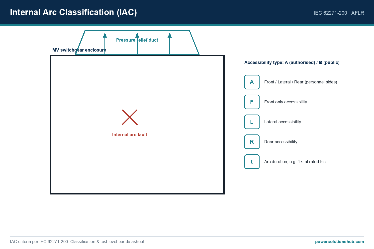
Ring main unit (RMU) for medium-voltage secondary distribution — compact sealed switchgear

Ring Main Units (RMU) — Types, Selection & Specifications

A ring main unit (RMU) is a compact medium-voltage switchgear assembly used to switch and protect secondary distribution networks: it connects a substation into the MV ring, switches the incoming and outgoing ring cables, and protects the MV/LV distribution transformer — typically rated up to 24 kV (families to 40.5 kV).

This pillar guide covers what an RMU does and how it works in a ring network, the main types and brand families, how a unit is configured from functional blocks, the key ratings to specify, and how to select one — for MV distribution projects across the Middle East and Gulf (including Egypt and Saudi Arabia), as well as North Africa, CIS and Sub-Saharan Africa.

What a ring main unit does

An RMU sits at the secondary distribution level. In a distribution “ring”, each substation is fed from two directions so a fault or maintenance on one section does not cut supply; the RMU provides the two ring load-break switches (incoming and outgoing) plus a transformer feeder that protects the local MV/LV transformer. Combining these functions in one compact, usually sealed enclosure is what distinguishes an RMU from a full primary switchgear line-up.

Ring main unit single-line diagram — two ring load-break switches plus a protected transformer feeder
RMU single-line: two ring load-break switches plus a protected transformer feeder (fuse-switch or circuit breaker).

It links up to the wider medium-voltage switchgear family: where primary switchgear feeds large loads, the RMU is the workhorse of compact secondary substations and kiosks.

How an RMU works in a ring network

Secondary distribution is usually built as an open ring. Substations are connected in a loop that runs from one primary source, through a string of distribution substations, back to another source — but the ring is deliberately left open at one point (a normally-open switch) so it operates radially. Each substation’s RMU carries two ring load-break switches, one for each direction of the ring cable.

The value of this arrangement is continuity of supply. If a cable section faults or needs maintenance, the operator opens the load-break switches on either side of that section to isolate it, then closes the normally-open point to feed the affected substations from the other direction. Supply is restored to almost all customers within minutes, without waiting for the cable repair. The RMU is the device that makes this switching possible at every node of the ring, which is why it is the standard building block of urban and industrial MV distribution.

The third function at each node is the transformer feeder: a tee-off from the ring that protects and supplies the local MV/LV distribution transformer, either through a switch-fuse combination or a circuit breaker with a protection relay (see below).

RMU types

RMUs are distinguished mainly by insulation medium and transformer-protection method:

  • Gas-insulated RMUs: the live parts sit in a sealed SF6 (or SF6-free) tank — compact and maintenance-free for life. Examples: Schneider RM6, ABB SafeRing / SafePlus and Siemens 8DJH. See the gas-insulated switchgear pillar for the insulation detail.
  • SF6-free RMUs: sealed units that use dry/clean air with vacuum interruption instead of SF6 — for example ABB SafeRing/SafePlus Air, a sealed dry-air ring main unit up to 24 kV with a global warming potential of 0 and a vacuum circuit-breaker with disconnector.
  • Air-insulated / modular RMUs: modular cubicles such as Schneider SM6 provide the same ring-plus-transformer function in an air-insulated, serviceable format, up to 36 kV.
  • Fixed vs extensible: an RMU can be a fixed, factory-set configuration or an extensible unit that can be enlarged on site as the network develops (for example SafeRing’s extendable version, or the RM6’s extensibility codes NE/RE/LE/DE).
Gas-insulated RMU compartment cross-section — sealed gas tank with the ring switches and transformer feeder
Most compact RMUs are gas-insulated: the ring switches, busbar and transformer feeder sit in a sealed, hermetic gas tank.

How an RMU is configured — functional units

A modern RMU is specified as a string of functional units (modules), so the single-line matches the substation exactly. Using the Schneider RM6 nomenclature as an example, the core functions are:

  • I — line (ring) switch: a switch-disconnector for an incoming or outgoing ring cable, rated 400 A or 630 A.
  • Q — fuse-switch combination: transformer protection by a switch plus MV fuses, for smaller transformers (up to about 2 000 kVA).
  • D / B — circuit-breaker function: transformer or feeder protection by a circuit breaker with a protection relay, for larger transformers (up to about 8 000 kVA).

A typical two-incomer, one-transformer substation is therefore an I-I-Q string (two ring switches plus a fuse-switch transformer feeder), while a substation whose transformer needs relay protection is an I-I-D (two ring switches plus a circuit-breaker feeder). The extensibility code chosen at order time decides whether more modules can be added later without replacing the unit — a double-extensible unit can grow on either side as the network develops. This “build what you need, extend later” approach is a large part of why RMUs dominate secondary distribution.

RMU brand families at a glance

The ring-main-unit families we most often supply:

Family Insulation Rated voltage Typical current Notes
Schneider RM6 SF6, sealed-for-life 12 / 17.5 / 24 kV 400 / 630 A Modular I/Q/D/B units; Isc up to 25 kA; extensible
ABB SafeRing / SafePlus SF6, sealed-for-life 12 / 24 kV (also 36 kV) up to 630 A RMU + extensible; fuse-switch or vacuum CB feeder
ABB SafeRing / SafePlus Air Dry air (SF6-free) up to 24 kV up to 630 A GWP = 0; vacuum CB with disconnector
Siemens 8DJH SF6, sealed-for-life up to 24 kV up to 630 A Vacuum CB; internal fault tested up to 21 kA
Schneider SM6 Air-insulated, modular 12–36 kV up to 630 A Serviceable modular cubicles; internal arc 12.5 / 16 / 20 kA 1 s

RMU vs primary switchgear

Criterion Ring main unit (RMU) Primary switchgear
Network level Secondary distribution Primary distribution
Function Ring switching + transformer protection, combined Full incomer/feeder/coupler line-up
Construction Compact, often sealed gas tank Larger, often withdrawable metal-clad
Typical current 400–630 A up to ~4000 A
Maintenance Sealed-for-life (gas) or serviceable (air) Serviceable, withdrawable devices
Typical use Compact substations, kiosks, MV rings Large substations, high-current busbars

For the full construction/insulation taxonomy, see the medium voltage switchgear pillar.

Transformer protection in an RMU

The transformer feeder is where the protection choice is made, and it is the point most worth getting right:

  • Switch-fuse combination (fuse-switch). For smaller distribution transformers — up to about 2 000 kVA — a load-break switch in series with MV fuses is a compact, economical and fast solution. The fuses clear high fault currents very quickly, and the standard governing this device is IEC 62271-105 (AC switch-fuse combinations for above 1 kV up to 52 kV).
  • Circuit breaker with a protection relay. For larger transformers — up to about 8 000 kVA — or where adjustable, selective protection and remote control are required, a circuit-breaker feeder with a numerical protection relay is used. This gives full overcurrent and earth-fault protection with settable curves and communications.

Choosing between them is mainly a question of transformer rating, the required selectivity with upstream and downstream devices, and whether remote control and metering are needed. Getting the fuse rating or the relay settings wrong is a common cause of nuisance tripping or, worse, unprotected faults — so the transformer feeder should always be coordinated with the rest of the protection scheme.

Key ratings to specify

Confirm these against the manufacturer’s datasheet for your configuration:

Parameter Typical RMU range
Rated voltage Ur 12 / 17.5 / 24 kV (families to 36–40.5 kV)
Rated normal (busbar) current 400 A / 630 A
Short-circuit breaking capacity up to ~25 kA (e.g. RM6 up to 25 kA)
Transformer protection switch-fuse (≤ ~2 000 kVA) or circuit breaker (larger)
Insulation SF6 / SF6-free sealed tank, or air-insulated modular
Standards IEC 62271-200; -105 (switch-fuse); -202 (compact substation)

Ambient-temperature derating

Rated current derates with ambient temperature — a key point for hot-climate projects. For a 630 A gas-insulated busbar, usable current falls as the ambient rises: for example, from 630 A at 40 °C down to about 575 A at 45 °C, 515 A at 50 °C, 460 A at 55 °C and 425 A at 60 °C. In Gulf and North-African installations where indoor temperatures routinely exceed 45 °C, this derating should be applied before confirming the rated current.

Selection criteria

  1. Insulation medium: gas-insulated (compact, sealed, harsh-environment), SF6-free sealed, or air-insulated modular (serviceable). See GIS vs AIS.
  2. Transformer rating → protection type: switch-fuse for smaller transformers (up to about 2 000 kVA), circuit breaker with a relay for larger ratings.
  3. Rated current: 400 A or 630 A busbars, then apply ambient-temperature derating for hot climates.
  4. Short-circuit level: confirm the network’s prospective fault current against the RMU’s rated breaking and making capacity.
  5. Extensibility: fixed or extensible, depending on whether the substation will be enlarged later.
  6. Regulatory: where SF6-free equipment is mandated, choose a dry-air or air-insulated family with equivalent ratings.

Standards

Ring main units are metal-enclosed switchgear to IEC 62271-200 (above 1 kV up to 52 kV). The transformer-protection switch-fuse combination follows IEC 62271-105, disconnectors and switches follow IEC 62271-102 / -103, circuit-breakers follow IEC 62271-100, and a compact secondary substation enclosure may be type-tested to IEC 62271-202. Sealed gas-insulated RMUs are “sealed-for-life” (sealed pressure system) designs.

Applications

RMUs are used in compact secondary substations, kiosks and building distribution — utilities, industry, infrastructure and renewable connection points — anywhere a compact unit is needed to ring-connect and protect an MV/LV transformer. Because the enclosure is compact and (for gas types) sealed, RMUs are also the natural choice for packaged and prefabricated substations to IEC 62271-202. A concrete example is the Schneider RM6 ring main unit, whose functional-unit range shows how a substation is built as a string of ring switches and transformer feeders.

RMUs in compact and prefabricated substations

One of the most common ways an RMU is deployed is inside a compact (packaged) substation — a factory-built enclosure, kiosk or concrete housing that contains the RMU, the MV/LV distribution transformer and the low-voltage board in one prefabricated unit, type-tested to IEC 62271-202. The RMU is the MV heart of this package: it brings the ring cables in, switches them, and protects the transformer, while the whole assembly is delivered ready to connect on site. Because gas-insulated RMUs are compact and sealed, they let the entire substation shrink to a footprint that fits an urban plot, a basement, an industrial yard or a renewable-plant collection point. For utilities rolling out many identical substations across a network — a frequent pattern in Gulf, North-African and CIS distribution projects — this standardised RMU-plus-transformer package shortens delivery and simplifies maintenance across the fleet.

What is a ring main unit (RMU)?

An RMU is a compact medium-voltage switchgear assembly that connects a substation into the MV ring, switches the incoming and outgoing ring cables and protects the MV/LV distribution transformer, typically up to 24 kV.

How does a ring main unit work?

In an open-ring network each substation is fed from two directions through the RMU’s two ring load-break switches; if one cable section faults, the operator isolates it and restores supply from the other direction, while the transformer feeder protects the local transformer.

What is the difference between an RMU and primary switchgear?

An RMU combines ring switching and transformer protection in one compact (often sealed) unit for secondary distribution, while primary switchgear is a larger line-up of incomer, feeder and coupler panels for high-current primary distribution.

Are ring main units gas-insulated or air-insulated?

Both exist: gas-insulated RMUs (e.g. Schneider RM6, ABB SafeRing/SafePlus, Siemens 8DJH) use a sealed SF6 or SF6-free tank, while air-insulated modular RMUs (e.g. Schneider SM6) provide the same function in a serviceable air-insulated format.

How is the transformer protected in an RMU?

Smaller transformers (up to about 2 000 kVA) are protected by a switch-fuse combination to IEC 62271-105; larger transformers use a circuit breaker with a protection relay for adjustable, selective protection.

What voltage and current are RMUs rated for?

Typical RMUs are rated 12, 17.5 and 24 kV with 400 A or 630 A busbars and short-circuit breaking capacity up to about 25 kA; some families extend to 36–40.5 kV.

Is there an SF6-free ring main unit?

Yes. Dry-air sealed RMUs such as ABB SafeRing/SafePlus Air deliver the same sealed, compact function up to 24 kV with a global warming potential of 0, using vacuum interruption instead of SF6.

Looking for Ring Main Units (RMU)?

Looking for high-quality medium voltage ring main units? We provide expert engineering support and reliable products for all your medium voltage needs.

For quotations and requests: info@electricistanbul.com

WhatsApp: +90 501 076 69 91