
An MV/LV substation is an electrical installation that transforms medium-voltage power (typically supplied by a utility ring main or radial feeder) down to low voltage for distribution to end users, using a coordinated set of MV switchgear, a distribution transformer, and LV switchboards housed in a single compact or built-up structure. This guide walks through the first-principles calculations engineers use to size an MV/LV substation — rated current, transformer capacity, cable sizing implications, and short-circuit withstand checks — plus the layout and standards considerations that turn a calculation into a safe, compliant installation. These fundamentals apply equally to utility distribution substations and industrial/commercial package substations across the Middle East and Gulf region including Egypt and Saudi Arabia, North Africa, CIS countries, and Sub-Saharan Africa, where compact substation deployment is central to grid expansion and industrial electrification programs.
Why substation sizing matters
Undersizing an MV/LV substation leads to thermal overload, nuisance tripping, and premature equipment failure. Oversizing wastes capital and increases footprint and short-circuit exposure unnecessarily. Correct sizing requires three linked calculations: (1) the rated current the load demands, (2) the transformer capacity that supplies that current at the chosen voltage, and (3) the fault current the switchgear and protection system must safely interrupt. Getting these three numbers right — and keeping them consistent between the MV switchgear, transformer, and LV board — is the core discipline of substation design.

The method: core sizing formulas
1. Rated current from apparent power (three-phase system):
I = S / (√3 × V)
Where I is the line current in amperes, S is the apparent power in kVA, and V is the line-to-line voltage in kV.
2. Transformer secondary current uses the same formula applied at the LV side voltage, and the transformer primary current uses it at the MV side voltage — the kVA rating (S) stays the same on both windings (ignoring losses), only V changes.
3. Short-circuit current estimate from transformer impedance:
Isc ≈ I_rated / Z(pu)
Where Z(pu) is the transformer’s per-unit impedance (e.g., a 6% impedance transformer gives Z(pu) = 0.06). This estimate ignores upstream network impedance and is a simplified worst-case starting point; a full fault study also includes source/grid impedance and cable impedance in series.
4. Cable/busbar current-carrying requirement: the conductor must be rated for at least the calculated I, derated for ambient temperature, grouping, and installation method per the applicable cable standard.
Worked example: sizing a 1000 kVA, 11 kV substation
Consider a compact substation supplying a commercial load, fed from an 11 kV network through a 1000 kVA transformer stepping down to 400 V LV distribution.
Step 1 — MV (primary) rated current:
I = S / (√3 × V) = 1000 / (1.732 × 11) ≈ 52.5 A
This is the current the MV switchgear feeder and the transformer’s MV winding must carry continuously.
Step 2 — LV (secondary) rated current:
I = S / (√3 × V) = 1000 / (1.732 × 0.4) ≈ 1,443 A
This is the current the LV main breaker, busbar, and outgoing feeders downstream of the transformer must be rated to handle.
Step 3 — Approximate LV-side short-circuit current, assuming a transformer impedance of 6% (Z(pu) = 0.06):
Isc ≈ I_rated / Z(pu) = 1,443 / 0.06 ≈ 24,050 A ≈ 24 kA
This tells the designer that the LV switchboard and its main breaker need a short-circuit breaking capacity comfortably above roughly 24 kA at the transformer terminals — the exact required rating is then confirmed by a full fault study including upstream and cable impedances, and by consulting the switchgear manufacturer’s verified rating.
Step 4 — MV-side fault contribution is generally dominated by the upstream network fault level rather than the transformer, so the MV switchgear’s rated short-circuit breaking current is selected primarily from the utility’s declared fault level at the point of connection, then confirmed against the transformer’s through-fault withstand duty.
This worked sequence — primary current, secondary current, approximate fault level — is the backbone of every MV/LV substation sizing exercise, whether the transformer is 250 kVA or 2500 kVA, and whether the primary voltage is 11 kV, 20 kV, or 33 kV.
Sizing reference table (illustrative worked values)
| Transformer rating | Primary voltage | Primary current (formula I=S/√3V) | Secondary voltage | Secondary current (formula I=S/√3V) |
|---|---|---|---|---|
| 500 kVA | 11 kV | ≈ 26.2 A | 400 V | ≈ 722 A |
| 1000 kVA | 11 kV | ≈ 52.5 A | 400 V | ≈ 1,443 A |
| 1600 kVA | 11 kV | ≈ 84.0 A | 400 V | ≈ 2,309 A |
| 1000 kVA | 20 kV | ≈ 28.9 A | 400 V | ≈ 1,443 A |
All figures above are illustrative calculations derived from the I = S/(√3×V) formula for engineering-guidance purposes, not manufacturer ratings.
Selection criteria and common pitfalls
- Match switchgear rated current to the worst-case feeder load, not just the transformer nameplate current — allow margin for future load growth.
- Verify short-circuit ratings across the whole chain: MV switchgear breaking current, transformer through-fault withstand, and LV breaker breaking capacity must all be coordinated; the weakest link sets the system’s real fault-withstand capability.
- Do not rely on the simplified Isc formula alone — a proper fault study incorporates upstream grid impedance, cable/busbar impedance, and multiple transformer contributions in parallel-fed systems.
- Account for altitude, ambient temperature, and enclosure ventilation when derating transformer and switchgear continuous current ratings.
- Coordinate protection relay settings with both the transformer inrush current and the calculated fault current so that MV protection discriminates correctly from LV protection — see our protection relay hub page for coordination principles.
- Select busbar and cable cross-sections using the calculated rated current plus derating factors, not the transformer’s kVA figure directly.
- Plan physical layout for IAC-rated arc-fault safety, adequate clearances, cable trench routing, earthing grid continuity, and operator access for withdrawable modules.
- Confirm transformer connection group and vector group compatibility between the MV switchgear protection scheme and the LV distribution board.
Layout and equipment building blocks
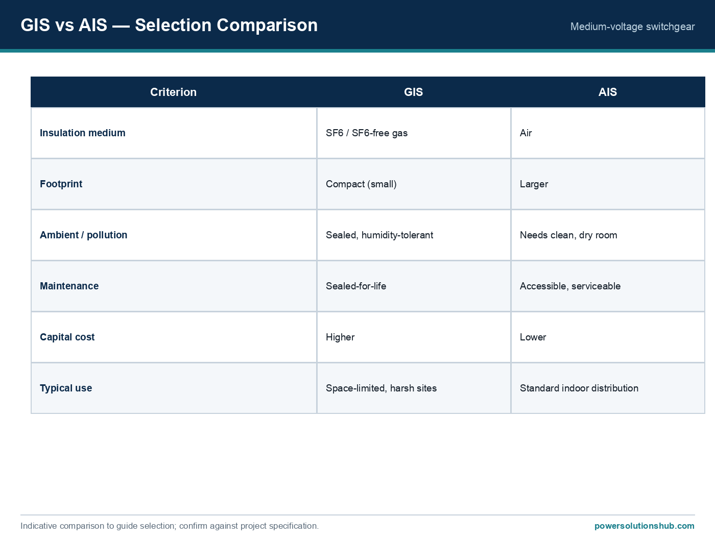
A typical MV/LV substation combines an MV incoming/outgoing switchgear panel or ring main unit, a distribution transformer (oil-filled or cast-resin dry-type), an LV switchboard with metering and outgoing feeders, and an earthing/grounding system tying all enclosures together. In compact substation packages, these three functional blocks are pre-engineered into a single housing or a small footprint arrangement, reducing on-site installation time versus a built-up substation assembled from separately sourced components. For guidance on selecting the MV switchgear building block itself, see our switchgear hub page; for transformer type selection (oil vs cast resin, vector groups, impedance selection), see our transformer hub page.
Standards governing MV/LV substation design
MV switchgear used in these substations is governed by IEC 62271 series standards covering rated voltage, rated current, and rated short-circuit breaking current for AC switchgear and controlgear. Power transformers are governed by the IEC 60076 series, which defines rated power, impedance, temperature rise, and testing requirements. LV switchboards and assemblies fall under the IEC 61439 series for low-voltage switchgear and controlgear assemblies. Earthing and general electrical installation safety practices are typically referenced against IEC 61936 for power installations exceeding 1 kV AC. Designers should always confirm the specific standard edition and any national deviations applicable to the project’s country of installation.
Related guides
See also our guides on medium voltage switchgear, gas-insulated switchgear and metal-clad switchgear.
What is the basic formula for sizing MV/LV substation current?
The rated current is calculated as I = S / (√3 × V), where S is the apparent power in kVA and V is the line-to-line voltage in kV. This formula is applied separately on the MV (primary) side and the LV (secondary) side of the transformer.
How do I estimate the short-circuit current at the LV side of a transformer?
A simplified approximation is Isc ≈ I_rated / Z(pu), using the transformer’s per-unit impedance. This gives a first-pass estimate; a complete fault study should also include upstream network and cable impedances for an accurate figure.
Why is the LV-side current so much higher than the MV-side current for the same transformer?
Because current is inversely proportional to voltage for a fixed kVA rating (I = S/(√3×V)). Stepping voltage down from, for example, 11 kV to 400 V increases current proportionally, which is why LV busbars and breakers must carry much higher rated currents than MV feeders for the same transformer capacity.
What is the difference between a compact substation and a built-up substation?
A compact substation integrates the MV switchgear, transformer, and LV switchboard into a single pre-engineered enclosure or small footprint package, whereas a built-up substation assembles these components separately on site, typically requiring more space and installation time.
Which IEC standards apply to MV/LV substation components?
MV switchgear is covered by the IEC 62271 series, power transformers by IEC 60076, and LV switchboards by IEC 61439. Installation and earthing practices are commonly referenced against IEC 61936 for installations above 1 kV AC.
How does transformer impedance affect switchgear selection?
A lower transformer impedance produces a higher short-circuit current on the LV side for the same kVA rating, which means the LV switchboard’s short-circuit breaking capacity must be selected with sufficient margin above the calculated fault level, as shown in the worked example.
Do I need to consider future load growth when sizing a substation?
Yes — sizing only for present load leaves no margin for expansion. Best practice is to size the transformer, switchgear rated current, and cable cross-sections with a growth margin above the calculated present-day rated current, subject to project-specific planning criteria.
Looking for compact substations?
Looking for high-quality compact substations? We provide expert engineering support and reliable products for all your medium voltage needs.
For quotations and requests: info@electricistanbul.com
WhatsApp: +90 501 076 69 91