

MV switchgear cubicle maintenance is the structured inspection, testing, and preventive-repair program applied to medium-voltage switchgear compartments — busbar, circuit breaker/RMU, cable, and low-voltage control sections — to detect degradation before it develops into an internal arc fault or unplanned outage. This guide walks through the physical fault mechanisms that occur inside MV cubicles, the first-principles calculations engineers use to size protection and judge diagnostic readings, a worked example, a maintenance decision table, and the governing IEC/IEEE framework. It is written for utility, industrial, and EPC engineers working across the Middle East and Gulf region (including Egypt and Saudi Arabia), North Africa, the CIS states, and Sub-Saharan Africa, where harsh ambient conditions and dust loading accelerate several of the fault modes discussed below.

Why Cubicle Faults Matter: The Physics Behind Failure Modes
An MV cubicle is essentially several failure-prone interfaces sharing one steel enclosure: bolted busbar joints, cable terminations, circuit breaker/contactor primary contacts, and CT/VT connections. Each interface can fail through one of a small number of well-understood mechanisms:
- Resistive heating at joints — a loose or oxidized bolted connection raises contact resistance R. Since dissipated power P = I²R, even a modest resistance increase at full load current produces a disproportionate temperature rise, accelerating insulation aging exponentially (per the Arrhenius-type relationship used in IEC/IEEE thermal life models).
- Partial discharge (PD) — voids, contamination, or mechanical stress in solid or air insulation ionize under the local electric field once it exceeds the insulation’s PD inception voltage, producing detectable RF pulses and audible/ultrasonic signatures long before a full breakdown occurs.
- Insulation tracking and moisture ingress — condensation on epoxy bushings, cable boxes, or support insulators forms conductive paths, especially in humid coastal or highly variable-climate sites.
- Mechanical wear — repeated breaker or RMU switching operations wear contact surfaces, springs, and interlocks, changing timing and contact pressure.
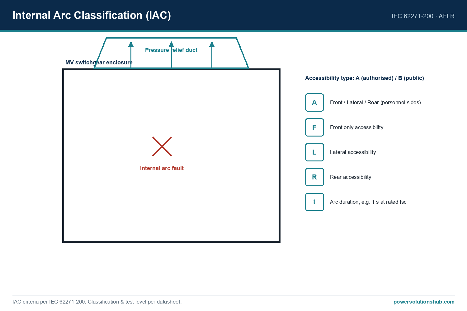
- Internal arc fault propagation — once initiated (from a joint failure, insulation tracking, or a dropped tool during maintenance), an internal arc generates extreme pressure and thermal energy inside the compartment; enclosure venting and internal-arc-classified (IAC) construction are designed to direct this energy away from operating personnel.
A structured maintenance program is aimed squarely at intercepting the first three mechanisms — thermal, PD, and insulation degradation — before they reach the arc-fault stage, and at controlling wear-related risk on the fourth through cycle counting and mechanism inspection. For background on the switchgear compartments themselves, see our medium voltage switchgear hub page and, for the protection side of this discussion, our [protection relay](/what-is-a-medium-voltage-protection-relay-mv-protection-relay/) resource.
The Method: Core Formulas Used in Cubicle Diagnostics
Four calculations recur constantly in MV cubicle maintenance work.
1. Rated/load current (used as the denominator for thermal-image or CT loading assessments):
I = S / (√3 × V)
where S is apparent power (kVA) and V is line-to-line voltage (kV).
2. Joint power dissipation from measured resistance:
P = I² × R
This tells you how many watts a degraded joint is dissipating at a given load current — the physical driver of the temperature rise seen on a thermal camera.
3. Thermal-rise comparative criteria (IEEE/NETA-style delta-T classification) — rather than one absolute temperature, maintenance standards classify severity by the difference between the suspect point and a similar reference component under similar load, and by absolute hot-spot temperature. This comparative approach corrects for ambient and loading variation between inspections.
4. Relative PD trending:
PD activity is normally trended in apparent charge (pC) or as a relative dB level from ultrasonic/TEV (transient earth voltage) sensors, compared against the cubicle’s own baseline reading rather than an absolute pass/fail number, since background noise and geometry vary cubicle to cubicle.
Worked Example: Diagnosing a Suspect Busbar Joint
Scenario. A 1000 kVA distribution transformer is fed at 11 kV. During a thermal survey, one incoming busbar joint reads noticeably hotter than the two adjacent phases.
Step 1 — Rated/load current.
I = S / (√3 × V) = 1,000,000 / (1.732 × 11,000) ≈ 52.5 A
For example, at full transformer load the busbar carries approximately 52.5 A per phase.
Step 2 — Estimate contact resistance from a micro-ohmmeter reading. Suppose a contact-resistance test on the suspect joint reads 500 µΓ (0.0005 Ω), against 150 µΩ on the healthy reference phases — roughly 3.3× higher.
Step 3 — Compute dissipated power at rated current.
P = I² × R = (52.5)² × 0.0005 ≈ 2756 × 0.0005 ≈ 1.38 W
By comparison, the healthy joint at 150 µΩ dissipates:
P_healthy = (52.5)² × 0.00015 ≈ 0.41 W
Step 4 — Interpret. The suspect joint is dissipating roughly 3.3 times more heat than its healthy neighbor for the same current — consistent with the elevated temperature seen thermally. Under IEEE/NETA-style delta-T criteria, a temperature difference of this order between similar components under similar loading is typically flagged for priority correction (tightening, cleaning, or replacement) well before the joint reaches a temperature that threatens the surrounding insulation.
Takeaway. This calculation illustrates why thermal imaging and micro-ohm testing are complementary: the thermal camera finds the anomaly quickly across the whole switchroom, while the resistance measurement quantifies why the joint is hot and gives you a trendable number for the maintenance record.
Cubicle Fault Modes vs. Diagnostic Method — Decision Table
| Fault Mode | Physical Cause | Primary Detection Method | Typical Maintenance Action |
|---|---|---|---|
| Loose/oxidized busbar or cable-lug joint | Contact resistance rise → I²R heating | Infrared thermography, micro-ohm test | Clean, re-torque, or replace joint hardware |
| Partial discharge in solid/air insulation | Voids, surface contamination, mechanical stress | PD sensors (TEV, ultrasonic, UHF) | Trend PD level; schedule targeted internal inspection or component replacement |
| Insulation tracking / moisture ingress | Condensation, dust bridging, coastal humidity | Visual inspection, insulation resistance (megger) test | Clean/dry compartment, improve heater/ventilation, reseal |
| Breaker/RMU mechanism wear | Repeated switching cycles, spring fatigue | Timing test, operation counter review, contact-wear gauge | Mechanism service, contact replacement per manufacturer cycle limit |
| CT/VT secondary or wiring fault | Loose terminal, insulation breakdown | Secondary injection test, insulation resistance test | Re-terminate, replace faulty CT/VT, verify protection relay response |
| Internal arc fault (worst case) | Propagation from any of the above, or foreign object | Arc-flash relay, pressure/light sensors, post-event inspection | Compartment isolation per IAC design; full root-cause investigation |
Selection Criteria for a Maintenance Program
- Inspection interval basis — set thermal and visual inspection frequency by criticality and load factor, not a single fixed calendar rule; heavily loaded or older cubicles warrant shorter intervals.
- Baseline data — record commissioning-stage thermal, resistance, and PD readings for every cubicle so future comparisons are trend-based rather than one-off absolute judgments.
- Access and safety design — favor cubicles offering safe LV-side diagnostic access (viewing windows, external TEV test points) so thermography and PD checks can be performed without opening live compartments.
- Withdrawable vs. fixed construction — withdrawable circuit breakers simplify isolation for maintenance and testing compared with fixed designs, at the cost of additional mechanical interlocking to inspect.
- Environmental protection — in dusty, high-humidity, or coastal GEO regions, verify enclosure sealing, anti-condensation heaters, and ingress protection are adequate for the site, since moisture and dust materially shorten insulation life.
- Documentation and trending software — a maintenance program is only as good as its ability to compare this year’s reading against last year’s; ensure resistance, thermal, and PD data are logged per-cubicle, per-phase.
Common pitfalls: judging thermal readings by absolute temperature alone instead of delta-T against a healthy reference phase; skipping micro-ohm testing after re-torquing a joint (so a “fixed” joint is never actually re-verified); neglecting mechanism-cycle counters on frequently switched RMUs; and treating PD readings as pass/fail rather than trending them over time. For upstream protection coordination that should back up any cubicle-level fault, see our protection relay guide, and for source-side considerations on the transformer feeding the switchgear, our transformer resource.
Governing Standards
MV switchgear cubicle design, type testing, and internal-arc classification are governed by IEC 62271-200 (AC metal-enclosed switchgear and controlgear for rated voltages above 1 kV and up to and including 52 kV), which defines internal arc classification (IAC) test procedures referenced when assessing arc-fault containment. General switchgear common clauses fall under IEC 62271-1. Insulation resistance and dielectric testing practices commonly follow IEC 60060 series test techniques, while infrared thermographic inspection practice for electrical equipment is commonly referenced against IEEE and national NETA-style maintenance testing guidelines. Site-specific maintenance intervals should always follow the equipment manufacturer’s instruction manual in conjunction with these standards.
Related guides
See also our guides on gas-insulated switchgear, ring main units and metal-clad switchgear.
What is the most common cause of MV cubicle failure?
Loose or oxidized busbar and cable-termination joints are among the most frequent root causes, because contact-resistance increases produce escalating I²R heating that can progress to insulation failure if not caught by thermographic or micro-ohm testing.
How often should MV switchgear cubicles be inspected?
Interval should be risk-based rather than fixed — driven by load criticality, ambient conditions, and equipment age — with thermal and visual inspections typically more frequent than full internal mechanism overhauls; always follow the manufacturer’s maintenance manual as the primary reference.
Can partial discharge testing be done without de-energizing the switchgear?
Yes — TEV (transient earth voltage) and ultrasonic PD sensors are designed for on-line, live measurement from the cubicle exterior, which is precisely why they are widely used as a routine, non-intrusive screening tool.
Why compare delta-T instead of an absolute temperature during thermography?
Because ambient temperature and load current vary between inspections and between phases, comparing a suspect point against a healthy reference component under the same load conditions gives a much more reliable severity indicator than a single absolute reading.
Does an internal arc fault always mean the switchgear was defective?
No — arc faults can originate from a maintenance error (dropped tool, incorrect isolation), foreign object ingress, or long-term undetected degradation such as a loose joint; IAC-classified enclosure design (per IEC 62271-200) is intended to protect personnel regardless of the initiating cause.
What is the difference between withdrawable and fixed circuit breaker maintenance?
Withdrawable breakers can be racked out to a test or isolated position for maintenance and testing without disturbing the busbar compartment, simplifying safe access, whereas fixed breakers generally require more extensive compartment isolation procedures for the same work.
How does climate affect MV cubicle maintenance needs in GEO regions like the Gulf or Sub-Saharan Africa?
High ambient temperature accelerates insulation aging kinetics, while humidity and dust loading common in coastal Gulf, North African, and Sub-Saharan sites increase the risk of tracking and contamination-driven partial discharge, generally justifying shorter inspection intervals and stronger enclosure sealing/heating provisions than in temperate climates.
Looking for medium voltage switchgear?
Looking for high-quality medium voltage switchgear? We provide expert engineering support and reliable products for all your medium voltage needs.
For quotations and requests: info@electricistanbul.com
WhatsApp: +90 501 076 69 91