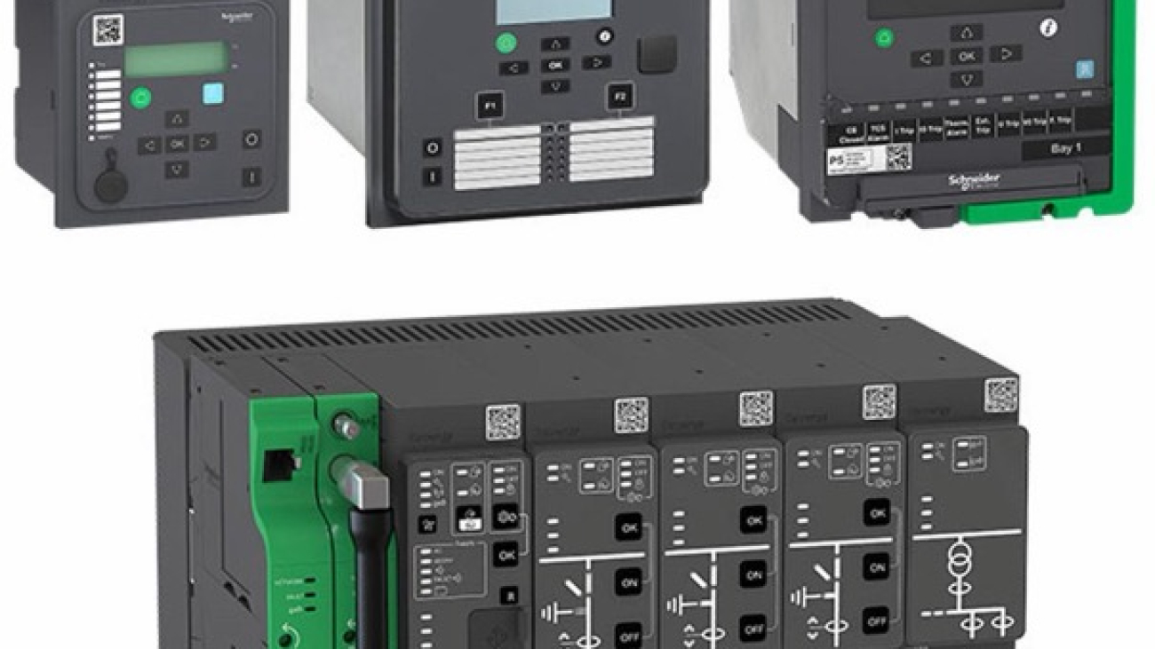
Schneider MiCOM Protection Relays – Advanced Solutions for Medium Voltage Networks
Schneider MiCOMprotection relays have long been recognized as reliable and high-performance solutions in medium voltage power systems. The MiCOM family offers a wide range of digital relays designed for feeder protection, transformer protection, line protection, and busbar applications. With advanced communication capabilities and precise fault detection features, these relays provide both safety and operational efficiency in modern electrical networks.
MiCOM Px20 Series Protection Relays
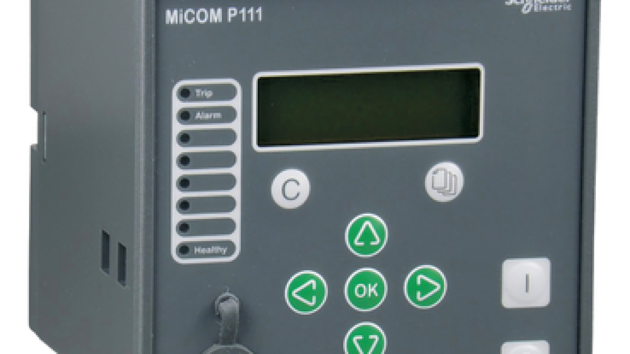
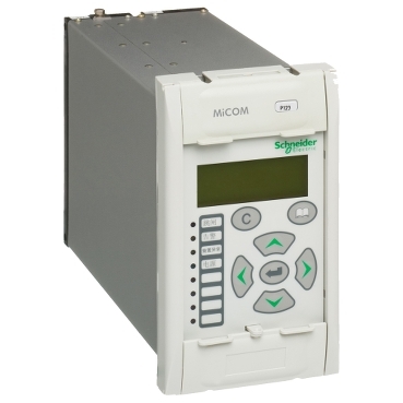
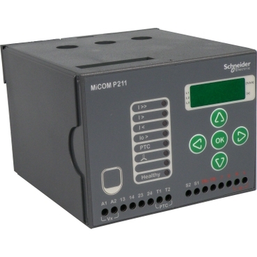
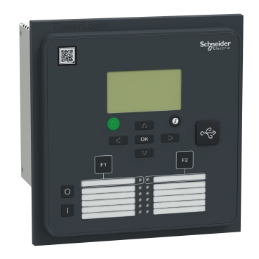
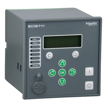
The MiCOM Px20 series, particularly the P12x models, is designed for standard medium voltage protection requirements. Models such as MiCOM P120, MiCOM P122, and MiCOM P111 are widely used for overcurrent and earth fault protection in distribution networks. These relays offer both directional and non-directional protection functions, making them suitable for radial and ring main systems.
The P12x series provides essential protection functions including instantaneous and time-delayed overcurrent (50/51), earth fault protection (50N/51N), and negative sequence protection. Some models in this series, such as MiCOM P122, also include additional features like thermal overload protection and breaker failure functions. The compact design and user-friendly interface of the Px20 series make it a practical choice for panel builders and contractors working on standard distribution projects. These relays deliver reliable performance while maintaining cost-effectiveness for typical medium voltage applications.
Schneider Micom Series Protection Relays
MiCOM P14x Series – Advanced Feeder Protection
The MiCOM P14x series, especially models like MiCOM P143, represents a more advanced level of feeder protection within the Schneider MiCOM range. These relays are specifically developed for incoming and outgoing feeder applications in medium voltage substations and industrial plants.
MiCOM P143 offers comprehensive protection functions including directional overcurrent, earth fault, and sensitive earth fault protection. It also provides advanced features such as fault location, disturbance recording, and multiple communication protocol support. The P14x series is known for its high accuracy in fault detection and strong coordination capabilities with other protective devices. This makes it particularly suitable for networks where selectivity and fast fault clearance are critical. The series combines robust hardware with flexible configuration options, allowing engineers to adapt the relay to various system requirements.
MiCOM Px40 Series – High-Performance Protection Platform
The Easergy MiCOM Px40 series is Schneider’s high-end protection relay platform, designed for more complex and critical medium voltage applications. This series includes specialized models for different protection needs. For example, the MiCOM P643 is widely used for transformer differential protection, offering fast and reliable detection of internal faults in power transformers.
Other models in the Px40 series provide distance protection, line differential protection, and busbar protection. These relays feature advanced communication options, including IEC 61850, and support redundant Ethernet architectures for high availability. The Px40 series is preferred in applications where high-speed operation, extensive recording capabilities, and integration with modern substation automation systems are required. With its modular design and powerful processing capabilities, MiCOM Px40 series delivers superior performance in demanding industrial and utility environments.
Schneider Micom Series Protection Relays
Schneider MiCOM Protection Relays for Reliable Power System Protection
Schneider MiCOM protection relays continue to be a trusted choice for medium voltage networks due to their proven reliability, wide range of protection functions, and strong communication features. From the cost-effective MiCOM P120 and MiCOM P122 models in the Px20 series to the advanced MiCOM P143 feeder protection relay and specialized units like MiCOM P643 in the Px40 series, Schneider offers scalable solutions for different application needs. These relays help improve system safety, reduce downtime, and support efficient operation in both new installations and retrofit projects.
Looking for MiCOM Protection Relay for your project?
Looking for reliable MiCOM protection relay, Schneider MiCOM, or specific models such as MiCOM P143, MiCOM P643, MiCOM P120, or MiCOM P122? We provide expert technical support and genuine Schneider Electric MiCOM relays tailored to your medium voltage protection requirements.
Schneider Easergy Protection Relays – P1, P3 and P5 Series Technical Guide
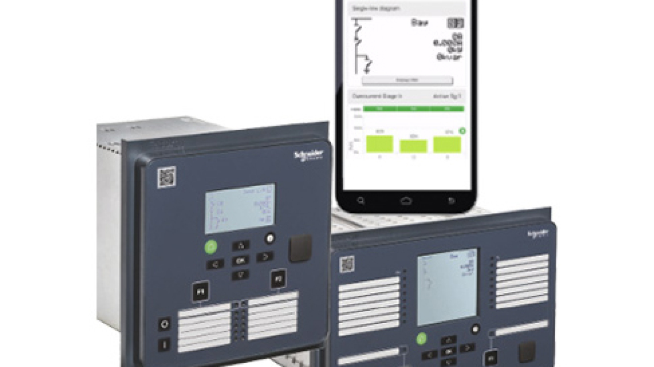
Schneider Easergyprotection relays represent Schneider Electric’s modern generation of compact and high-performance digital relays developed specifically for medium voltage applications. The Easergy family is designed to meet today’s requirements for reliability, communication, cybersecurity, and ease of use in industrial, utility, and commercial power systems.
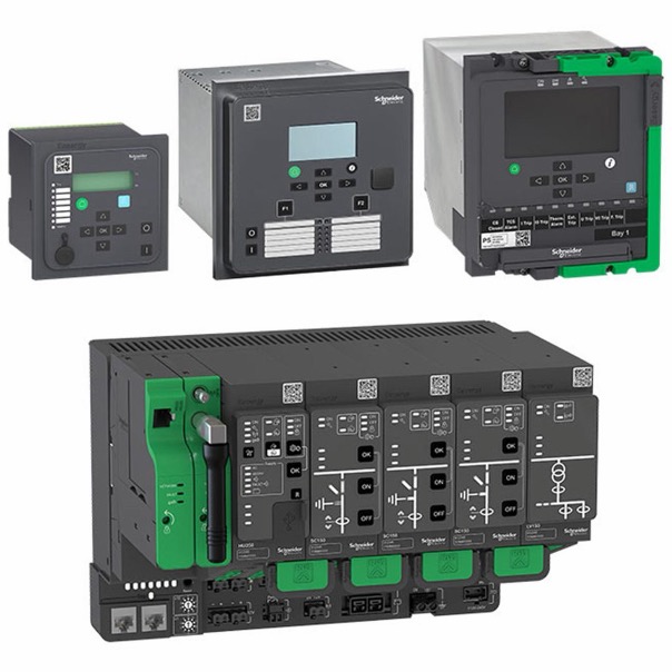
The Easergy range consists of three main series — Easergy P1, Easergy P3, and Easergy P5 — each targeting different levels of application complexity while maintaining Schneider’s high standards of quality and performance.
Easergy P1 Protection Relay
Easergy P1 is the entry-level model in the Easergy family. It is a compact, simple, and cost-effective protection relay developed for basic medium voltage protection needs.
This relay is particularly suitable for standard feeder protection, motor protection, and simple transformer protection applications. Despite its smaller size and simpler architecture, the P1 relay delivers essential protection functions with high reliability and fast response times.
Key advantages of Easergy P1 include:
Easy configuration and commissioning
Compact design suitable for space-limited panels
Reliable performance in standard distribution applications
Cost-effective solution for panel builders and contractors
Easergy P1 is often preferred in projects where simplicity, fast delivery, and basic protection requirements are the main priorities.
The Easergy P3 series, including models such as Easergy P3U20 and Easergy P3U30, is the most widely used and versatile relay in the Easergy family. It offers an excellent balance between functionality, size, and performance.
Easergy P3 provides more than 40 protection functions in a compact housing. It supports advanced features such as:
Fast arc flash detection and protection
Compatibility with LPCT and LPVT sensors
Ethernet communication
Full IEC 61850 protocol support
The P3 relay is designed for standard to medium complexity medium voltage applications. It is highly suitable for feeder protection, motor protection, and transformer protection in industrial plants and distribution networks.
Easergy P3U20 and Easergy P3U30 models offer different levels of input/output capacity and functionality, allowing engineers to choose the most appropriate version according to project requirements. The series is known for its user-friendly configuration software and strong performance in demanding industrial environments.
Because of its feature-rich yet compact design, Easergy P3 has become one of the most popular choices among Schneider protection relay users for new installations and retrofit projects.
Easergy P5 Protection Relay
Easergy P5 is the most advanced relay in the Easergy family. It is designed for critical and complex medium voltage applications where high performance, flexibility, and safety are essential.
Key features of Easergy P5 include:
Comprehensive protection from basic overcurrent to advanced differential protection
Built-in arc flash protection
Redundant Ethernet communication options
Advanced automation and logic capabilities
Withdrawable design for easy maintenance and fast replacement
Enhanced cybersecurity features
The withdrawable design of Easergy P5 significantly reduces downtime during maintenance or relay replacement, making it particularly valuable in critical power systems such as large industrial plants, data centers, and utility substations.
Easergy P5 also offers superior integration capabilities within Schneider’s EcoStruxure architecture, enabling advanced digital monitoring and remote management.
Comparison of Easergy P1, P3, and P5
Feature
Easergy P1
Easergy P3 (P3U20/P3U30)
Easergy P5
Application Level
Basic / Entry-level
Standard to Medium Complexity
Advanced / Critical
Number of Protection Functions
Essential functions
40+ functions
Comprehensive + Advanced
Arc Flash Protection
Basic
Yes
Advanced
Communication
Standard
Ethernet + IEC 61850
Redundant Ethernet + Advanced
Design
Fixed
Compact
Withdrawable
Typical Use
Simple feeders & motors
Industrial & Distribution
Critical substations & plants
Key Advantages of Schneider Easergy Relays
The entire Easergy family shares several important strengths:
High measurement accuracy and fast fault detection
Strong communication capabilities including IEC 61850
Easy configuration through dedicated software
Support for modern sensor technologies (LPCT/LPVT)
Cybersecurity features (especially in P5)
Seamless integration into Schneider EcoStruxure ecosystem
These features make Easergy relays suitable for both new projects and modernization of existing medium voltage installations.
Schneider Protection Relay
Schneider Easergy protection relays offer a complete and scalable solution for medium voltage protection needs. While Easergy P1 provides a simple and economical option for basic applications, Easergy P3 (including P3U20 and P3U30) delivers the best balance of features and performance for most standard and industrial projects. For the most demanding applications, Easergy P5 stands out with its advanced functions, withdrawable design, and enhanced cybersecurity.
With their modern design, strong communication capabilities, and reliable protection performance, Easergy relays have become a preferred choice for many engineers and project owners working on medium voltage systems.
Looking for Schneider Protection Relay for your project?
Looking for high-performance Schneider Easergy, Easergy P3, Easergy P3U20, Easergy P3U30, or complete medium voltage protection solutions? We provide expert technical support with genuine Schneider Electric products tailored to your requirements.
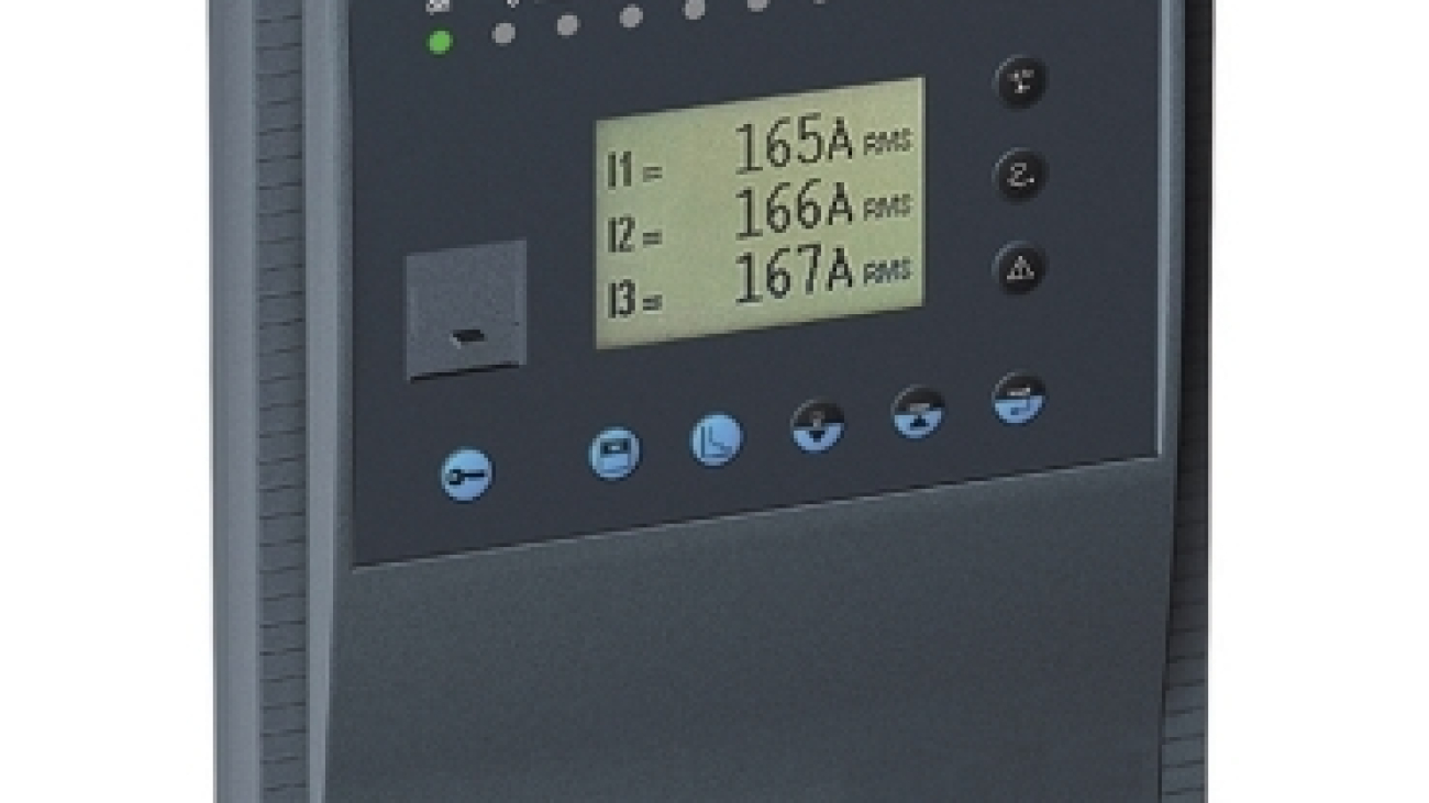
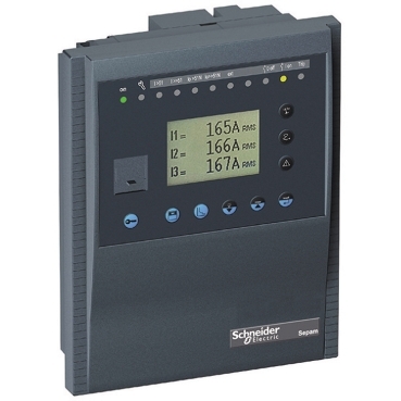
Schneider Sepam is one of the most established and reliable digital protection relay families offered by Schneider Electric for medium voltage applications. The Sepam range has been widely adopted across industrial plants, utilities, infrastructure projects, and commercial facilities due to its proven performance, modular design, and ease of use.
Among the Sepam series, Sepam 20 (also referred to as Sepam S20) stands out as the ideal solution for standard and common medium voltage protection requirements. It provides a perfect balance between functionality, reliability, and cost-effectiveness for typical distribution network applications.
Schneider Protection Relay
What is Schneider Sepam Protection Relay?
Schneider Sepam protection relay is a microprocessor-based digital relay designed to protect, control, and monitor electrical equipment in medium voltage systems. It continuously measures current and voltage signals from instrument transformers, analyzes them according to pre-set protection functions, and issues trip commands to circuit breakers when abnormal conditions are detected.
The Sepam family includes several application-specific models. Each model is optimized for a particular type of equipment or protection requirement, making selection straightforward for engineers and panel builders.
Sepam Series 20 (Sepam 20 / Sepam S20) Overview
Sepam 20 is the entry-to-mid level range within the Sepam family. It is specifically designed for standard applications in substations, feeders, transformers, motors, and generators. Despite being positioned as a standard solution, it offers comprehensive protection functions, advanced metering, and reliable communication capabilities.
Key characteristics of Sepam 20 include:
Dedicated models for different applications (S20 for feeders, T20 for transformers, M20 for motors, etc.)
High measurement accuracy and fast response time
Built-in disturbance recording and event logging
Self-diagnostic functions for improved reliability
Modular architecture that allows addition of I/O modules and communication interfaces
Main Protection Functions of Sepam 20
Sepam 20 provides a wide range of protection functions commonly required in medium voltage networks:
Overcurrent Protection (ANSI 50/51)
Earth Fault Protection (ANSI 50N/51N)
Thermal Overload Protection (ANSI 49RMS)
Undervoltage and Overvoltage Protection (ANSI 27/59)
Negative Sequence / Current Unbalance Protection (ANSI 46)
Breaker Failure Protection (ANSI 50BF)
Automatic Reclosing (ANSI 79)
Cold Load Pickup and Inrush Blocking
These functions make Sepam relay suitable for both basic and moderately complex protection schemes in distribution systems.
Sepam S40 – Advanced Version for Demanding Applications
While Sepam 20 is ideal for standard applications, Sepam S40 offers enhanced capabilities for more demanding protection requirements. It includes additional protection functions, more advanced logic capabilities, and greater flexibility in communication and I/O configuration.
Sepam S40 is often selected when the application requires more sophisticated protection logic, additional metering features, or integration into larger automation systems.
Key Advantages of Schneider Sepam Relays
Schneider Sepam relays offer several important benefits that have contributed to their widespread adoption:
High Reliability: Proven performance with hundreds of thousands of units installed worldwide
User-Friendly Interface: Intuitive front panel and easy-to-use configuration software
Modular Design: Flexible architecture that can be adapted to different project requirements
Strong Communication Capabilities: Support for Modbus and IEC 61850 protocols for seamless integration into SCADA and DCS systems
Comprehensive Diagnostics: Advanced self-monitoring and event recording for faster fault analysis and maintenance
Excellent Selectivity: Precise coordination with other protective devices in the network
Communication and System Integration
Modern Schneider Sepam relays support multiple communication protocols, enabling easy integration into both new and existing automation systems. Optional communication modules allow connection via serial or Ethernet networks. This capability is particularly valuable in industrial plants and utility substations where centralized monitoring and remote control are required.
Typical Applications of Sepam 20 and Sepam S40
Sepam 20 and Sepam S40 are commonly used in:
Medium voltage distribution substations
Industrial plant incoming and outgoing feeders
Transformer protection in distribution networks
Motor protection in industrial facilities
Generator protection in small to medium power plants
Infrastructure projects such as airports, metro systems, and commercial complexes
Their robust design and reliable performance make them suitable for both indoor and outdoor installations when properly housed.
Schneider Sepam Relay
Why Choose Schneider Sepam Protection Relay?
Engineers and project owners choose Schneider Sepam for several reasons:
Proven track record with decades of field experience
Good balance between features and cost for standard MV applications
Easy configuration and commissioning, reducing engineering time
Strong after-sales support and availability of spare parts
Compatibility with Schneider’s broader ecosystem of medium voltage equipment
Whether the project requires basic overcurrent and earth fault protection or more advanced functions with communication capabilities, the Sepam range offers suitable solutions.
Schneider Sepam protection relay, particularly the Sepam 20 and Sepam S40 models, remains a trusted and widely used solution for medium voltage protection. With its application-specific models, comprehensive protection functions, modular design, and reliable communication options, Sepam provides an excellent combination of performance, flexibility, and value.
For standard distribution applications, Sepam 20 offers the ideal balance of features and cost. For more demanding requirements, Sepam S40 provides enhanced functionality while maintaining the same user-friendly approach that has made the Sepam family successful worldwide.
Looking for Schneider Protection Relay for your project?
Looking for reliable Schneider Sepam, Sepam 20, Sepam S40, or complete Schneider relay solutions for medium voltage protection? We offer expert technical support and genuine Schneider Electric products tailored to your distribution and industrial needs.
Schneider Protection Relay – Comprehensive Guide for Medium Voltage Applications
Schneider protection relay solutions are among the most trusted and widely used in medium voltage electrical networks worldwide. Schneider Electric offers a complete and scalable range of digital protection relays designed for reliable protection, control, and monitoring of feeders, transformers, motors, generators, busbars, and capacitors.
In modern power systems, a protection relay acts as the intelligent brain of the electrical network. It continuously monitors current, voltage, frequency, and other parameters, detects faults quickly, and sends trip commands to circuit breakers. Schneider Electric provides robust, flexible, and communication-ready relays that meet the demanding requirements of industrial plants, utilities, and commercial facilities.
Main Schneider Relay Families by Application
Schneider organizes its protection relays according to specific applications, making it easier for engineers and contractors to select the right solution:
Feeder Protection Relays — For incoming and outgoing medium voltage lines
Transformer Protection Relays — Differential, thermal, and backup protection
Motor Protection Relay — Advanced thermal, unbalance, and locked rotor protection
Generator Protection Relays
Busbar and Capacitor Bank Protection
Overcurrent Protection Relay and Voltage Protection Relay solutions
1. Sepam Series
The Sepam range is a proven, modular, and user-friendly Schneider protection relay family. It has been widely used for many years in transformer, motor, feeder, and generator protection applications.
With models such as Sepam 20, Sepam 40, and Sepam 80, this series offers excellent metering accuracy, comprehensive event recording, disturbance recording, and strong communication capabilities. Sepam relays are known for their reliability and ease of use, making them a popular choice for both new installations and retrofit projects.
Schneider Sepam Protection Relay
2. Easergy Series – P1, P3, P5 (PowerLogic)
The Easergy series represents Schneider’s modern generation of compact and powerful medium voltage protection relays. This family (previously known as Easergy P3 in some markets) is designed for today’s smart grid and industrial requirements.
Easergy P1: Entry-level protection relay offering simplicity, reliability, and cost-effectiveness. Ideal for basic feeder and motor protection where straightforward functionality is sufficient.
Easergy P3 (PowerLogic P3): The most popular model in the series. It is a compact yet powerful relay offering more than 40 protection functions, including advanced overcurrent, earth fault, and arc flash protection relaycapabilities. It supports LPCT/LPVT sensors, Ethernet communication, and full IEC 61850 protocol. Easergy P3 provides an excellent balance between features, size, and performance for standard MV applications.
Easergy P5 (PowerLogic P5): The advanced model designed for more complex and demanding applications. It offers enhanced functionality, multiple Ethernet protocols, embedded web server configuration, and superior performance in large industrial plants and utility substations.
Schneider Easergy Protection Relay
3. MiCOM Series (Easergy MiCOM Px40)
MiCOM (now part of the Easergy MiCOM Px40 series) is Schneider’s high-end, utility-grade protection relay platform. It is designed for transmission, distribution, and critical high-voltage applications.
Models such as MiCOM P14x (feeder), P24x (motor), and other variants provide advanced protection functions including distance protection, differential protection, and interconnection protection. These relays are known for their scalability, high accuracy, and robust performance in harsh environments.
Schneider Micom Protection Relay
Key Features of Schneider Protection Relays
Schneider Electric relay products stand out with several important advantages:
Fast and accurate fault detection with high selectivity
Easy configuration and setting using dedicated software tools
Multiple communication protocols including Modbus, DNP3, and full IEC 61850
Robust hardware design suitable for harsh industrial and outdoor environments
Advanced diagnostics, event recording, and disturbance recording
Support for modern sensor technologies (LPCT/LPVT)
Whether you need a simple overcurrent protection relay, a motor protection relay, or a sophisticated differential protection relay, Schneider offers scalable solutions that can be tailored to your specific application.
How to Choose the Right Schneider Protection Relay
When selecting a Schneider protection relay, consider the following factors:
Required protection functions (ANSI codes)
Application type (feeder, transformer, motor, generator, etc.)
Communication requirements (IEC 61850, Ethernet, etc.)
Need for arc flash protection
Sensor type (conventional CT/VT or LPCT/LPVT)
Panel space and mounting requirements
Future expansion and integration needs
Schneider’s clear product segmentation (Sepam, Easergy P1/P3/P5, and MiCOM) helps users quickly identify the most suitable relay for their project.
Schneider protection relay solutions provide reliable, flexible, and future-ready protection for medium voltage networks. From the proven Sepam series to the modern and compact Easergy P3 and advanced Easergy P5, Schneider offers a complete portfolio that meets the needs of industrial, commercial, and utility applications.
With strong communication capabilities, advanced protection functions, and excellent build quality, Schneider relays help improve system reliability, reduce downtime, and enhance personnel safety through features such as arc flash protection.
For any medium voltage protection project, choosing the right Schneider relay ensures long-term performance and peace of mind.
Looking for Schneider Protection Relay for your project?
Looking for high-performance Schneider protection relay, Schneider relay, Schneider overload relay, or complete medium voltage protection solutions? We provide expert technical support with genuine Schneider Electric products tailored to your requirements.
A medium voltage (MV) protection relay is the intelligent device that continuously monitors an MV circuit’s current, voltage, frequency and power, detects faults such as short circuits and earth faults, and trips the circuit breaker to isolate the faulty section — protecting transformers, cables, motors and generators and keeping the rest of the network in service.
This pillar guide explains how modern numerical relays work, the ANSI protection functions and relay types, the main relay families we supply, how to select and coordinate a relay, and the governing standards — for MV distribution and industrial projects across the Middle East and Gulf (including Egypt and Saudi Arabia), as well as North Africa, CIS and Sub-Saharan Africa.
What an MV protection relay is (and where it fits)
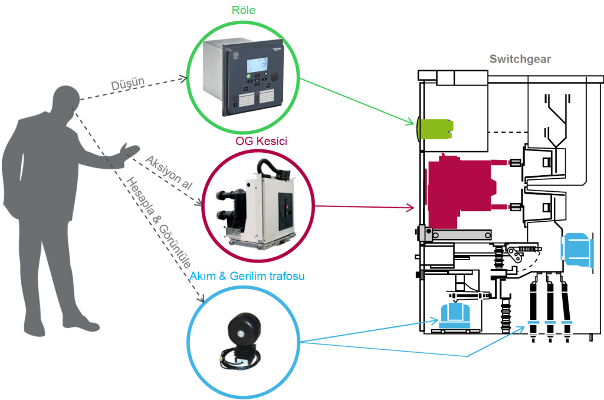
In power systems, electricity is generated, stepped up for transmission, stepped down at substations and finally distributed to end users. Without protection, a single fault — a short circuit or earth fault — can destroy equipment and cause widespread outages. The protection relay is the “brain” that prevents this: it detects the fault in milliseconds and sends a trip signal to the circuit breaker to clear it. The relay sits inside the medium-voltage switchgear panel, wired to the current and voltage transformers, and it is the component that turns a passive switchboard into a self-protecting system.
How medium voltage protection relays work
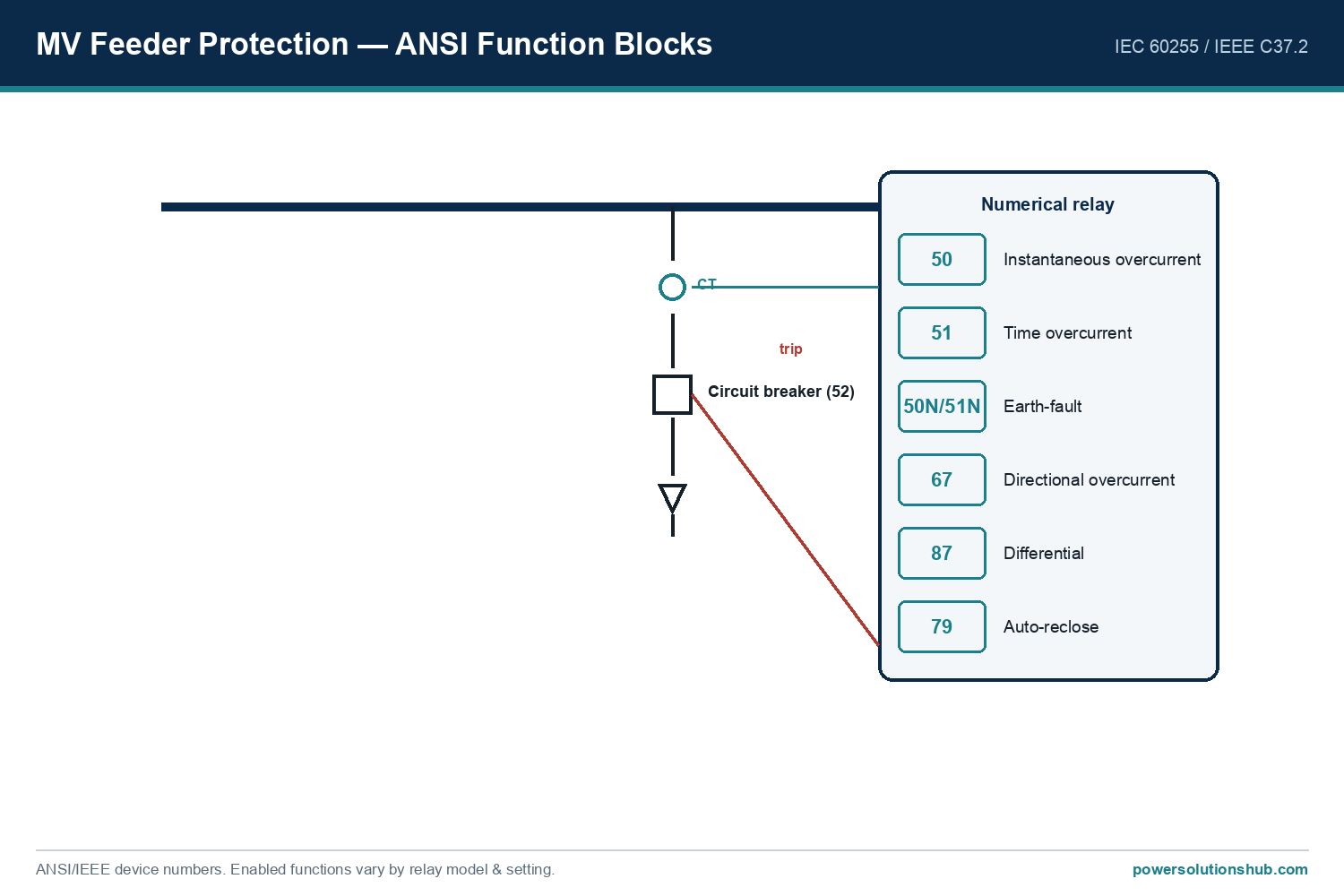
Modern MV relays are microprocessor-based (numerical) devices. They receive scaled signals from the current transformers (CTs) and voltage transformers (VTs), sample and analyse them in real time, and compare the measured quantities against pre-set protection settings. When a fault is detected — for example overcurrent, earth fault or undervoltage — the relay decides, based on its programmed logic and time curves, whether to trip the breaker.
MV feeder protection: the CT feeds the numerical relay, which runs ANSI functions (50/51, 50N/51N, 67, 87…) and trips the circuit breaker (device 52).
Beyond tripping, a modern relay also provides event and disturbance recording, metering, self-supervision and communication (IEC 61850, Modbus, DNP3) for remote monitoring and fault analysis. The ABB REF615, for example, is a dedicated feeder protection relay built on the IEC 61850 standard with transient/intermittent earth-fault protection and a transient disturbance recorder, while the Siemens SIPROTEC 5 platform supports IEC 61850 Edition 2 including 9-2 process-bus applications and integrated arc protection.
How A Protection Relay Works
Relay technology: from electromechanical to numerical
Understanding the three generations helps when a network has mixed equipment:
Electromechanical relays — the original technology, using discs and coils. Robust but limited to a single function each, with no communication.
Static (solid-state) relays — analogue electronics; more functions, still limited.
Numerical (digital) relays — today’s standard: one microprocessor device carries many protection functions, metering, recording and communication, and is configured entirely in software.
Almost all new MV installations use numerical relays, and the relay families below are all numerical platforms.
Protection functions and ANSI codes
Relay functions are standardised by ANSI/IEEE device numbers (IEEE C37.2) and characterised to IEC 60255. A relay is selected primarily by the protection functions it must provide. The most frequently used MV codes are:
ANSI Code
Protection Function
Common Application
27
Undervoltage
Voltage protection
50
Instantaneous Overcurrent
Overcurrent protection
51
Time Overcurrent
Overcurrent protection
50N / 51N
Instantaneous / Time Earth Fault
Earth-fault protection
59
Overvoltage
Voltage protection
67
Directional Overcurrent
Feeder protection
67N
Directional Earth Fault
Directional earth-fault
46
Negative-Sequence (Unbalance)
Motor protection
49
Thermal Overload
Motor / transformer protection
81 O/U
Over / Under Frequency
Frequency protection
87T
Transformer Differential
Transformer protection
87L
Line Differential
Line protection
87G
Generator Differential
Generator protection
21
Distance
Distance protection
50BF
Breaker Failure
Backup protection
An engineer specifies a relay by listing the ANSI functions the application needs — for example a feeder relay typically needs 50/51 (overcurrent), 50N/51N (earth fault) and often 67 (directional), while a transformer relay adds 87T (differential) and 49 (thermal).
Types of medium voltage protection relays
Relays are grouped by application, each with a typical ANSI set:
Feeder protection relay — for incoming and outgoing feeders; overcurrent (50/51), earth fault (50N/51N) and directional functions (67/67N). The ABB REF615 is a dedicated feeder relay.
Motor protection relay — overload (49), phase unbalance (46), locked-rotor and earth-fault protection.
Generator protection relay — differential (87G), reverse power, and frequency protection.
Busbar protection relay — fast differential protection of the busbar zone.
Arc-flash protection relay — detects an internal arc optically and trips in milliseconds to limit damage and protect personnel.
Protection coordination and relay curves
Overcurrent protection is not just “trip when the current is too high” — it must be graded so that the relay closest to the fault trips first and the upstream relays act only as back-up. This selectivity is achieved with the inverse-time curves defined in IEC 60255: as the fault current rises, the tripping time falls, and the curve shape is chosen from standard inverse (SI), very inverse (VI), extremely inverse (EI) or definite-time characteristics. A downstream feeder relay is set on a faster curve (or lower time multiplier) than the upstream incomer, so a feeder fault is cleared by the feeder relay while the incomer holds back by a coordination margin (typically a few hundred milliseconds).
Directional overcurrent (67) adds another dimension: in a ring or parallel-fed network, the relay must know the direction of the fault current to trip only for faults in its own zone. Differential protection (87) works differently again — it compares the current entering and leaving a protected zone (a transformer, busbar or cable) and trips on any difference, giving fast, selective protection without a time delay. Getting these settings and their coordination right across the whole scheme is the core engineering task, and it depends directly on the network’s fault levels — see short circuit in power systems.
Schneider Protection Relays
Relay families we supply
We supply and support the main global numerical relay platforms; each has its own in-depth guide:
ABB — REF615 (dedicated feeder protection, IEC 61850) and the wider Relion family.
Each family offers different models with varying numbers of protection functions, communication options and I/O configurations; the linked guides give the model-level detail.
Choosing between relay families
With several strong numerical platforms available, the choice between families usually comes down to a few practical factors rather than raw protection capability, since all the leading platforms cover the standard ANSI functions:
Existing installed base. Matching the relay family already used across a site simplifies spares, settings tools and operator training — a common reason to standardise on one platform.
Communication and automation. If the substation is built around IEC 61850 with GOOSE interlocking or a process bus, choose a platform with mature IEC 61850 support (for example ABB REF615 or Siemens SIPROTEC 5).
Application fit. A dedicated feeder relay (REF615) is efficient for a feeder; a modular platform (SIPROTEC 5) suits a substation needing many function combinations from one hardware family; Schneider Easergy, Sepam and MiCOM cover feeder, transformer and motor duties across their ranges.
Configuration and lifecycle tools. The quality of the setting software, testing support and long-term firmware maintenance is often the deciding factor over a 15–20 year life.
Our role is to match the relay to the protection scheme, the communication architecture and the existing installed base — not simply to the datasheet.
Communication and IEC 61850
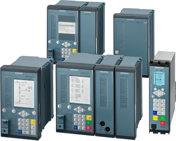
Modern MV relays are also communication nodes. IEC 61850 is the dominant substation-automation standard: it standardises how relays exchange data over Ethernet (GOOSE messaging for fast interlocking and protection signalling, MMS for SCADA), and its Edition 2 with 9-2 process bus digitises the CT/VT signals themselves. Relays such as the ABB REF615 (built on IEC 61850) and Siemens SIPROTEC 5 (IEC 61850 Edition 2, process bus) make substation-wide protection, control and monitoring interoperable across vendors. Modbus and DNP3 are also widely supported for legacy SCADA.
Siemens Protection Relays
How to select and coordinate a relay
Selecting the right relay is only half the job; the settings and coordination are the other half.
Required functions. List the ANSI functions the application needs (feeder, transformer, motor…) and choose a relay model that provides them.
CT/VT inputs. Confirm the relay’s rated current input (1 A / 5 A), voltage inputs and the number of analogue/digital I/O.
Communication. Match the substation’s protocol (IEC 61850, Modbus, DNP3) and redundancy needs.
Settings and selectivity. Calculate settings so the relay is selective (coordinated) with upstream and downstream devices — only the faulty section trips, the rest stays in service. This uses time grading, current grading and logic discrimination, with the overcurrent curves defined in IEC 60255 (standard inverse, very inverse, extremely inverse).
Even the best relay will mis-operate if its settings are wrong, so protection coordination is calculated for the whole scheme, not one relay in isolation. For the fault levels that drive these settings, see short circuit in power systems.
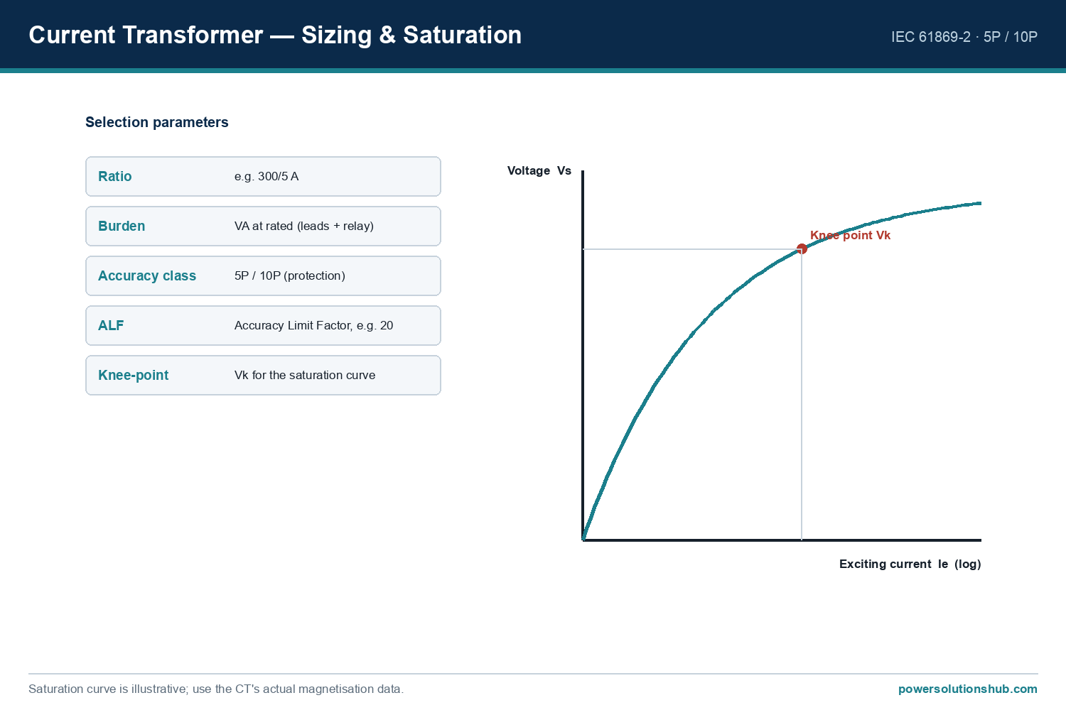
The relay is only as good as its CT/VT inputs: the current transformer's ratio, class and knee-point must suit the protection function.
Testing, commissioning and the relay lifecycle
A protection relay only protects if it has been correctly set and proven. Before a relay is put into service it is commissioned by secondary injection: a test set injects simulated currents and voltages into the relay’s inputs and verifies that each protection function picks up at the right value and trips in the right time, and that the trip actually operates the circuit breaker. Numerical relays make this far easier than older technology, because the settings, the measured values and the event and disturbance records can all be read out digitally and archived.
Over the relay’s life, the same numerical platform supports self-supervision (the relay continuously checks its own health and raises an alarm on a fault), periodic testing, and firmware updates. When an older electromechanical or static scheme is modernised, a numerical relay retrofit typically replaces a whole panel of single-function relays with one multi-function device, adding IEC 61850 communication, metering and disturbance recording at the same time — a common upgrade path in ageing substations across the region. This lifecycle view matters when specifying: a relay is a 15–20 year asset whose communication and testing capabilities are as important as its raw protection functions.
Standards
MV protection relays are characterised and tested to the IEC 60255 series (measuring relays and protection equipment), their device functions are numbered to IEEE C37.2 (ANSI), and their communication follows IEC 61850 for substation automation. Relays installed in switchgear also operate within the switchgear’s IEC 62271 framework.
What is a medium voltage protection relay?
It is a numerical device that monitors an MV circuit’s current and voltage, detects faults such as short circuits and earth faults, and trips the circuit breaker to isolate the faulty section, protecting equipment and maintaining supply.
What are ANSI protection codes?
ANSI/IEEE device numbers (IEEE C37.2) identify each protection function — for example 50/51 overcurrent, 50N/51N earth fault, 67 directional overcurrent and 87 differential — and a relay is specified by the ANSI functions it provides.
What is the difference between a feeder, transformer and motor relay?
A feeder relay uses overcurrent, earth-fault and directional functions (50/51, 50N/51N, 67); a transformer relay adds differential (87T) and thermal (49); a motor relay adds unbalance (46) and locked-rotor protection.
Which protection relay brands do you supply?
We supply the main numerical platforms: ABB REF615/Relion, Siemens SIPROTEC 4 and 5, and Schneider Easergy, Sepam and MiCOM — each with its own detailed guide.
What is IEC 61850 and why does it matter?
IEC 61850 is the substation-automation standard that lets relays from different vendors exchange data over Ethernet (GOOSE, MMS) and, in Edition 2, digitise CT/VT signals over a process bus — enabling interoperable, substation-wide protection and control.
Why is relay selectivity (coordination) important?
Correct settings ensure only the faulty section is isolated while the rest of the network keeps running; this needs time grading, current grading and discrimination between upstream and downstream relays.
Looking for MV Protection Relays?
Looking for high-quality medium voltage protection relays — feeder, transformer, motor, differential or arc-flash protection from ABB, Siemens and Schneider? We provide expert engineering support and reliable products for all your medium voltage needs.
Medium voltage (MV) switchgear is the complete assembly of switching, protection, control and measurement equipment used to distribute electrical power at voltage levels above 1 kV and up to about 40.5 kV, built as metal-enclosed or metal-clad panels to international standard IEC 62271-200.
This pillar guide explains the components inside an MV panel, the main types of switchgear — by insulation medium and by construction — how they compare, the classification and ratings you need to specify, the shift toward SF6-free equipment, and how to select the right panel. It is written for MV distribution projects across the Middle East and Gulf (including Egypt and Saudi Arabia), as well as North Africa, CIS and Sub-Saharan Africa.
What MV switchgear is
MV switchgear integrates several essential components into a single, safe, easy-to-operate unit. It provides safe operation, fault isolation, load switching and reliable supply in distribution substations, industrial plants, renewable plants and both step-up and step-down substations. A modern panel is built as a compact, modular metal-enclosed or metal-clad cubicle, and the main components are:
Circuit breaker — the main switching and fault-interrupting device. Modern MV breakers are almost always vacuum (the arc is interrupted in a vacuum bottle), though SF6 interrupters are also used; the device follows IEC 62271-100.
Disconnector and earthing switch — provide visible isolation and safe earthing of an isolated circuit; they follow IEC 62271-102. The earthing switch typically has a short-circuit making capacity, and mechanical interlocks make it impossible to earth a live circuit.
Instrument transformers — current and voltage transformers that scale primary quantities down for metering and protection. See the dedicated guides on the current transformer and voltage transformer.
Protection relay — the numerical protection relay that measures current and voltage and trips the breaker on a fault, with ANSI/IEC protection functions and IEC 61850 communication.
Busbars, cable terminations and surge arresters — the busbars distribute current between panels, the cable terminations connect the MV cables (see plug-in cable termination), and surge arresters limit transient overvoltages.
Low-voltage compartment — houses the control, protection and auxiliary circuits.
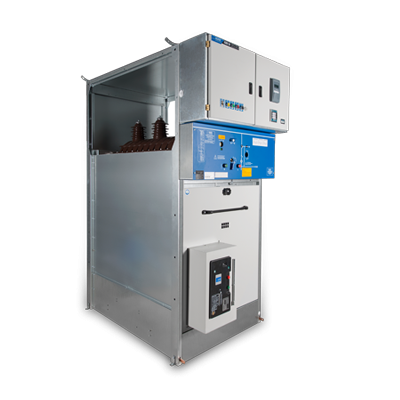
Metal Enclosed Switchgears
Types of MV switchgear — two independent axes
A common source of confusion is treating “GIS”, “AIS”, “metal-clad” and “RMU” as one list of alternatives. In fact they describe two independent things:
Insulation medium — how the live parts are insulated: Air-Insulated (AIS) or Gas-Insulated (GIS).
Construction format — how the panel is built and compartmented: metal-clad (compartmented, withdrawable), metal-enclosed cubicle, or ring main unit (RMU) (compact, usually sealed).
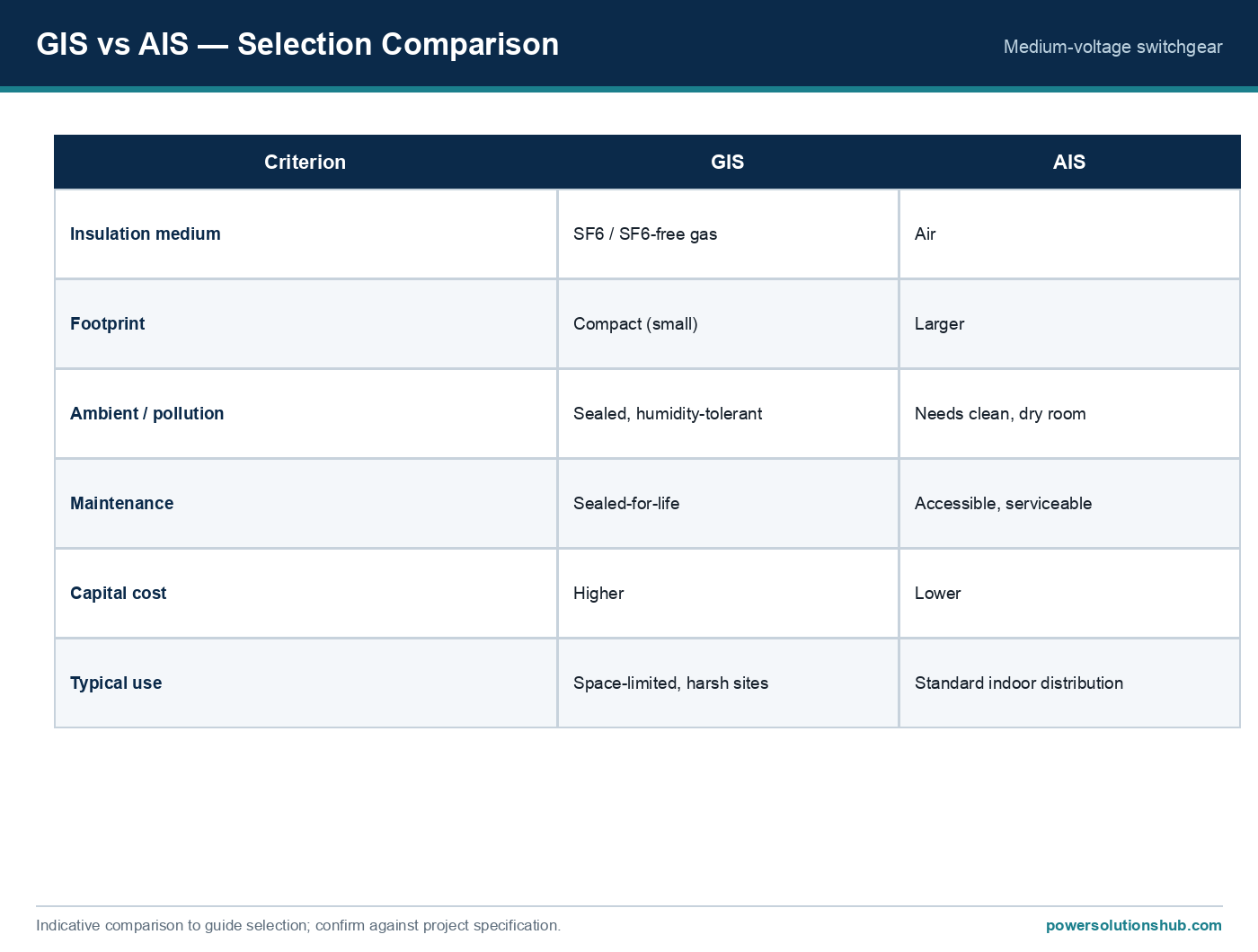
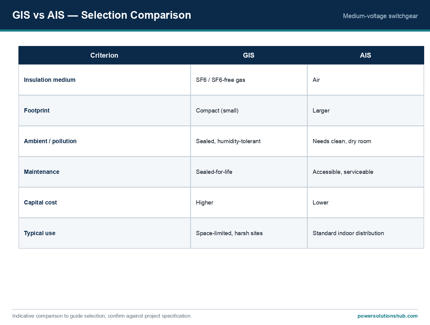
So a panel is described by both — for example a metal-clad panel is normally air-insulated, while a ring main unit is normally gas-insulated. The table below summarises the four terms you will meet most often.
Type
Axis
Insulation
Construction
Typical level
Notes
Air-Insulated (AIS)
Insulation
Air
Cubicle or metal-clad
Primary & secondary
Larger, serviceable, lower cost; needs a clean, dry room
A further construction choice is whether the circuit breaker is fixed-mounted or withdrawable. In a withdrawable (draw-out) design — typical of metal-clad primary switchgear — the breaker sits on a truck that can be racked between the service, test and isolated positions, and fully removed for maintenance or replacement while the busbar and cable compartments stay in their state. This maximises continuity of supply and makes maintenance safe and fast, at the cost of a larger, more expensive panel. In a fixed-mounted design — typical of compact secondary switchgear and gas-insulated RMUs — the breaker is built into the sealed unit; it is simpler and more compact, and because the unit is sealed-for-life it needs little internal maintenance in the first place. The right choice again follows the network level: withdrawable for high-current primary boards where serviceability is paramount, fixed-mounted for compact, sealed secondary units.
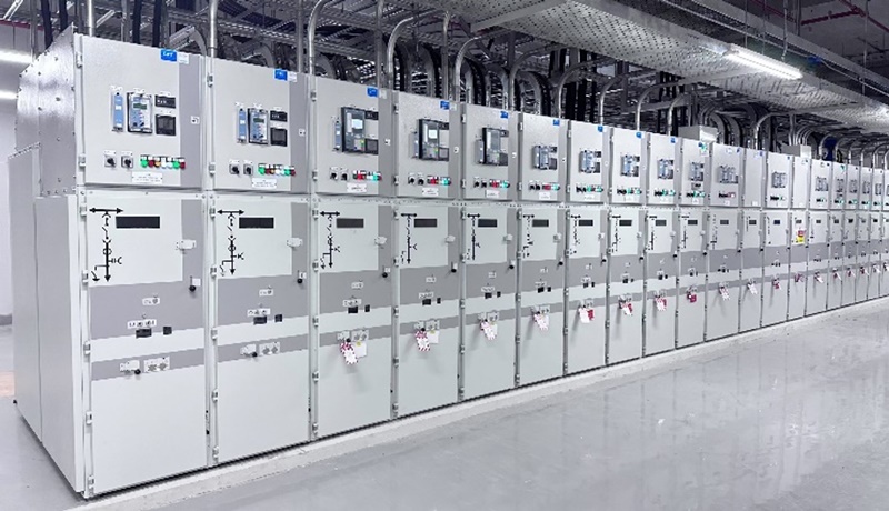
Metal Clad Switchgears
Primary vs secondary distribution
Another way to place a panel is by its role in the network:
Primary distribution switchgear sits close to the source — at the incoming substation feeding several outgoing feeders at high busbar current. It is typically an air-insulated, metal-clad, withdrawable line-up: for example ABB UniGear ZS1 handles up to 24 kV with busbar currents to 4000 A and short-circuit levels to 63 kA (at 12–17.5 kV). Withdrawable breakers allow a faulty unit to be racked out and replaced while keeping the rest of the board in service.
Secondary distribution switchgear sits deeper in the network, at the many small substations that step MV down to LV. It is typically a compact ring main unit (usually gas-insulated), rated 400–630 A, combining ring switching and transformer protection in one sealed unit — see ring main units.
Choosing the level is usually obvious from the single-line diagram; the more nuanced choices are insulation medium, construction and classification, covered next.
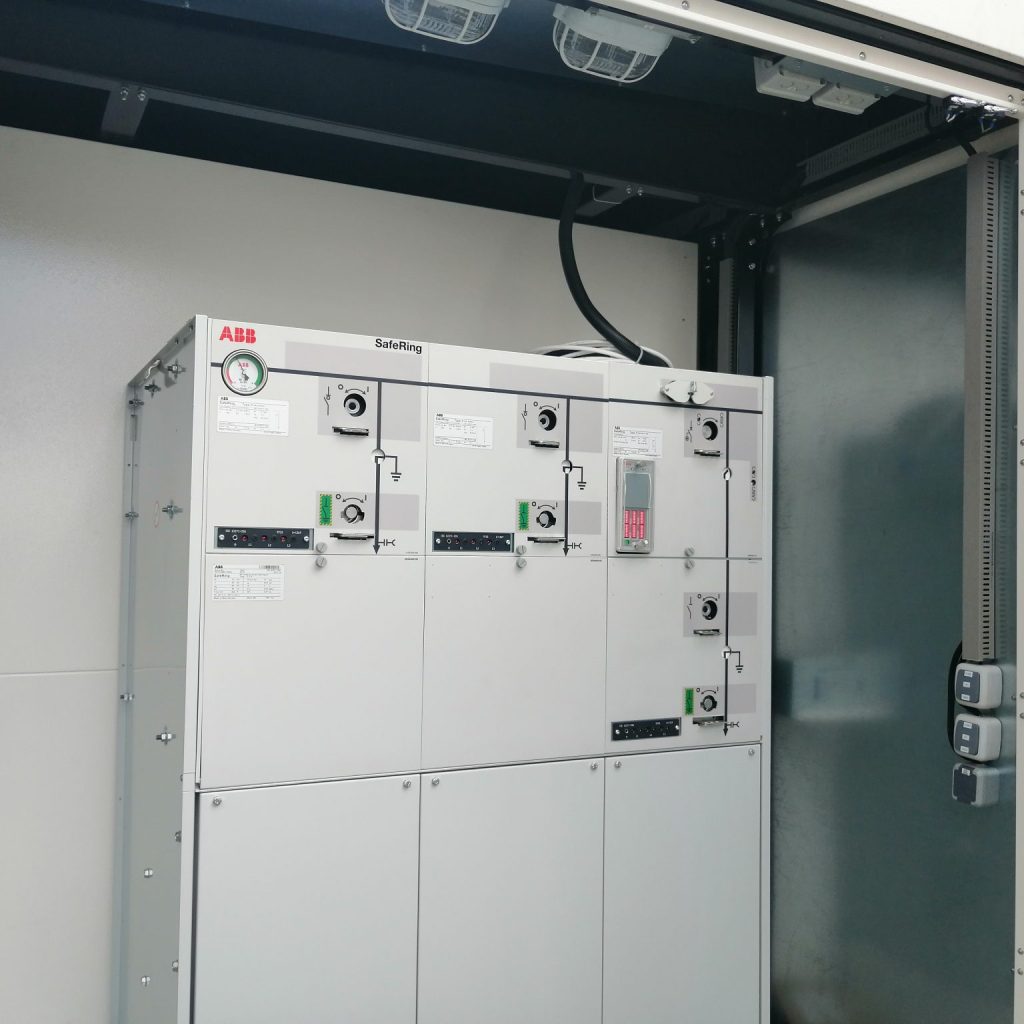
RMU Switchgear
How to choose
The choice between air-insulated and gas-insulated switchgear — and between a metal-clad line-up and a compact RMU — depends on:
Space and environment. Space-limited, hot, dusty or humid sites favour compact, sealed GIS/RMU; standard indoor rooms with maintenance access suit AIS.
Network level. Large primary substations with high busbar currents use metal-clad, withdrawable AIS; secondary distribution rings use compact RMUs. See ring main units.
Maintenance strategy. Sealed-for-life GIS minimises internal maintenance; withdrawable metal-clad maximises serviceability and continuity of supply.
Total cost of ownership. GIS has a higher capital cost but lower maintenance and footprint; AIS has a lower initial cost but needs the space and controlled environment.
Regulatory constraints. Where SF6-free equipment is required, choose a dry-air or air-insulated family with equivalent ratings (see below).
Classification of MV switchgear
MV switchgear is classified to IEC 62271-200 using three key parameters — the same parameters that appear on every reputable datasheet:
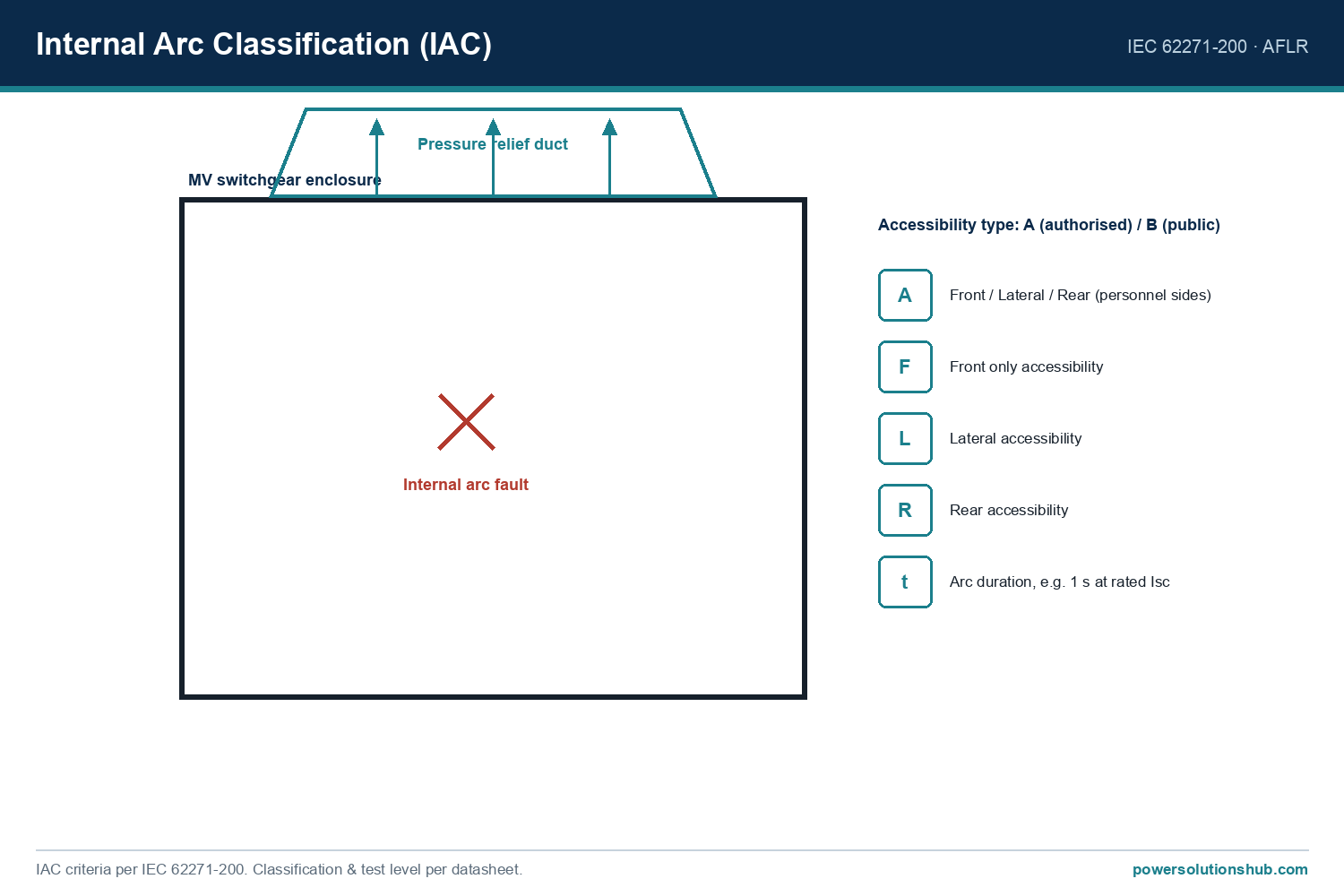
Internal Arc Classification (IAC): accessibility during an internal-arc fault, given as accessibility type A (authorised personnel) or B (public) and the accessible sides F (front), L (lateral) and R (rear), together with the tested arc current and duration (for example AFLR 20 kA, 1 s).
Loss of Service Continuity (LSC): how much of the switchgear must be shut down to work on one part — LSC1 (all in one compartment), LSC2A (switching devices accessible with busbars live), LSC2B (both cable and busbar compartments can stay live while working on the device compartment).
Partition class:PM (metal partitions) or PI (insulating partitions).
Internal-arc classification to IEC 62271-200: accessibility types and the AFLR accessible sides.
Reading a switchgear datasheet
Put together, a datasheet line such as “24 kV, 630 A, 25 kA 1 s, IAC AFLR 25 kA 1 s, LSC2B, PM” tells you: the panel is rated 24 kV and 630 A; it withstands a 25 kA short-circuit for 1 s; in an internal arc it is tested to 25 kA for 1 s with the front, lateral and rear sides protected for authorised personnel; both cable and busbar compartments can stay energised while working on the switching-device compartment (LSC2B); and the partitions between compartments are earthed metal (PM). Learning to read this line is the single most useful skill when comparing offers from different manufacturers.
Typical technical specifications
Typical MV switchgear ratings across the 12–40.5 kV range are:
Parameter
Typical range
Rated voltage Ur
12 / 24 / 36 kV (up to 40.5 kV)
Rated normal current
630 A (up to ~4000 A on primary metal-clad)
Short-circuit breaking capacity
16 / 20 / 25 kA (up to ~63 kA on primary)
Internal-arc withstand
e.g. 16–25 kA for 1 s
Standard
IEC 62271-200
Air-insulated switchgear needs larger clearances (for 36 kV systems the minimum busbar air clearance is typically 35–36 cm), whereas gas-insulated switchgear achieves the same insulation level in a much smaller volume thanks to the high dielectric strength of the gas.
SF6-free switchgear — the regulatory shift
For decades SF6 was the standard gas for compact MV switchgear, but it is a potent greenhouse gas (GWP roughly 23,000 times CO₂) now restricted by regulations such as the EU F-gas Regulation (EU 2024/573). The market response is SF6-free equipment that keeps the compact, sealed concept using dry / clean air with vacuum interruption — for example ABB SafeRing/SafePlus Air and Schneider SM AirSeT — with a global warming potential of 0 and comparable ratings. When specifying new switchgear, it is worth checking whether the project or utility mandates SF6-free equipment; the gas-insulated switchgear pillar covers the SF6-free options in detail.
Design and safety features
Quality MV switchgear from manufacturers such as ABB, Schneider, Siemens and others integrates: mechanical interlocks to prevent mis-operation; visible isolation and earthing; pressure-relief for internal-arc faults; integrated protection relays with IEC 61850 communication; a modular design for extending the line-up; and conformal coating on electronics for harsh environments. Together these ensure personnel safety, equipment protection and high reliability.
Applications
MV switchgear is used in primary and secondary distribution substations, industrial plants and factories, renewable energy plants (wind and solar), commercial buildings and infrastructure, and mining and oil & gas facilities. The choice between air- and gas-insulated switchgear depends on available space, maintenance strategy, environmental conditions and total cost of ownership.
Standards
Internationally, MV switchgear is designed and tested to the IEC 62271 series. The key parts are:
Standard
Scope
IEC 62271-1
Common specifications for high-voltage switchgear and controlgear
IEC 62271-100
Alternating-current circuit-breakers
IEC 62271-102
Disconnectors and earthing switches
IEC 62271-103
Switches for above 1 kV up to 52 kV
IEC 62271-105
Switch-fuse combinations
IEC 62271-200
AC metal-enclosed switchgear and controlgear (1 kV–52 kV)
Individual markets add national specifications (for example TEDAŞ technical specifications in Türkiye), but the IEC 62271 series is the common global baseline. Selecting the right type, the correct classification (LSC and IAC) and a reputable manufacturer ensures long-term reliability, personnel safety and operational efficiency.
MV switchgear is the assembly of switching, protection, control and measurement equipment used to distribute power above 1 kV up to about 40.5 kV, built as metal-enclosed or metal-clad panels to IEC 62271-200.
What is the difference between AIS and GIS?
AIS insulates the live parts with air and needs a larger, clean, dry room but is lower cost and serviceable; GIS encloses the live parts in a sealed gas tank, so it is compact, sealed-for-life and tolerant of humidity and pollution, at a higher capital cost.
Is a ring main unit the same as GIS?
Not exactly. “Ring main unit” describes the construction/role (compact secondary-distribution switchgear with ring switches and a transformer feeder), while “GIS” describes the insulation (sealed gas). Most RMUs are gas-insulated, but the two terms describe different things.
What is the difference between primary and secondary switchgear?
Primary switchgear sits at the incoming substation with high busbar currents (often metal-clad, withdrawable AIS up to ~4000 A), while secondary switchgear sits deeper in the network at compact MV/LV substations (usually ring main units, 400–630 A).
What do LSC and IAC mean on a switchgear datasheet?
LSC (Loss of Service Continuity) states how much must be shut down to work on one part (LSC1, LSC2A, LSC2B); IAC (Internal Arc Classification) states the accessibility and the tested arc current and duration during an internal-arc fault (e.g. AFLR 20 kA, 1 s).
Which standard governs MV switchgear?
The governing international standard is IEC 62271-200 (AC metal-enclosed switchgear for rated voltages above 1 kV up to 52 kV), supported by other parts of the IEC 62271 series and national specifications where they apply.
Is SF6-free MV switchgear available?
Yes. SF6-free families use dry/clean air with vacuum interruption (e.g. ABB SafeRing Air, Schneider SM AirSeT) to deliver the same compact, sealed performance with a global warming potential of 0, in line with regulations such as the EU F-gas Regulation.
Looking for MV Switchgear?
Looking for high-quality medium voltage switchgear — air-insulated, gas-insulated, metal-clad or ring main units — from leading brands? We provide expert engineering support and reliable products for all your medium voltage needs.
Transformer Vector Group and Connection Types (Vector Group of Transformer)
A vector group of transformer, also known as transformer connection group, defines how the primary and secondary windings of a three-phase transformer are connected and the resulting phase shift between them. Understanding the vector group of transformer is essential for correct transformer selection, system design, and especially for parallel operation of transformers.
Three-phase transformers can have their windings connected in different configurations: Star (Y), Delta (D), or Zigzag (Z). These connections determine important electrical characteristics such as neutral availability, harmonic behavior, and phase displacement.
Transformer Connection Types
Star Connection (Y or y): Windings are connected to a common neutral point. A neutral conductor is available. Denoted with capital “Y” for primary and lowercase “y” for secondary.
Delta Connection (D or d): Windings are connected in a closed triangle. No neutral point is available. Denoted with “D” or “d”.
Zigzag Connection (Z or z): Usually used on the secondary side. Each phase winding is split into two halves and connected in a zigzag pattern. This connection provides good performance under unbalanced loads and helps suppress certain harmonics.
The vector group is written with the primary connection first (capital letter), followed by the secondary connection (lowercase letter), and then a number indicating the phase shift.
How Vector Group Numbers Work
The number in the vector group represents the phase angle displacement between primary and secondary voltages in multiples of 30 degrees.
For example:
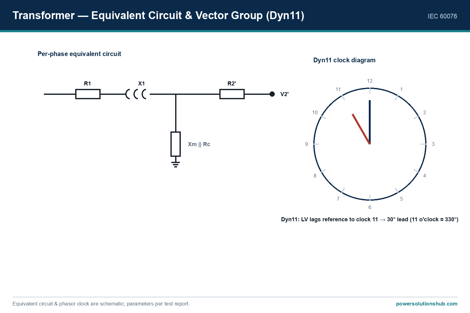
Dyn11 → Phase shift = 30° × 11 = 330° (or -30°)
Ynyn0 → Phase shift = 0°
Yzn5 → Phase shift = 30° × 5 = 150°
This standardized notation allows engineers to quickly understand the electrical relationship between primary and secondary sides.
Most Common Transformer Vector Groups
Dyn11 Transformer: The most widely used vector group in distribution networks. Primary: Delta (D) Secondary: Star with neutral (yn) Phase shift: 330° (or -30°)
Ynyn0: Both primary and secondary are star connected with neutral. Phase shift: 0°.
Ynd11: Often used in step-up applications. Primary: Star with neutral Secondary: Delta Phase shift: 330°.
Yzn5 / Yzn11: Primary star, secondary zigzag. Preferred for low-power transformers (up to 250 kVA) to handle unbalanced loads effectively.
Why is Dyn11 transformer preferred?
Third harmonic currents circulate within the delta primary and do not appear on the secondary side.
The star secondary provides a neutral point, which is required for 400V distribution systems in residential and industrial applications.
Excellent performance under both balanced and slightly unbalanced loads.
Standard choice for distribution transformers in many countries, including Turkey.
Ynyn0 Transformer Both primary and secondary are star connected with neutral. Phase shift is 0°. This group is often used in transmission systems and when zero phase displacement is required.
Ynd11 Transformer Primary is star with neutral, secondary is delta. Commonly used in step-up applications such as generator transformers in power plants and renewable energy facilities. The neutral on the primary side allows grounding through a neutral resistor for fault current limitation.
Dy0 Transformer Primary delta, secondary star. Phase shift is 0°. Used in some distribution applications where zero phase displacement is needed.
Yzn11 / Yzn5 Transformer Primary star, secondary zigzag. These groups are preferred for low power transformers (typically up to 250 kVA) supplying areas with high single-phase load (such as rural villages or small settlements). The zigzag connection helps balance the load across phases and reduces neutral current issues.
Importance of Vector Group in Parallel Operation of Transformers
One of the most critical requirements for parallel operation of transformer is that all transformers must have the same vector group.
If two transformers with different vector groups (for example, Dyn11 and Yyn0) are connected in parallel, a phase displacement will exist between their secondary voltages. This will cause large circulating currents to flow between the transformers even when there is no external load. These circulating currents lead to overheating, increased losses, and potential damage to the transformers.
Therefore, when planning to connect transformers in parallel, verifying that the vector groups are identical is mandatory.
How to Choose the Right Vector Group
The correct vector group of transformer depends on several factors:
System requirements for neutral (earthing)
Need to suppress harmonics (especially 3rd harmonic)
Whether the transformer will operate in parallel with existing units
Application type (distribution, step-up, industrial, or rural)
Local standards and utility specifications
In Turkey and many other countries, Dyn11 is the standard for distribution transformers because it meets both technical and operational needs of modern 400V networks..
The vector group of transformer is much more than just a technical label. It directly affects system compatibility, harmonic performance, neutral availability, and the ability to operate transformers in parallel. Among all groups, the Dyn11 transformer stands out as the most common and practical choice for distribution systems due to its excellent harmonic suppression and neutral provision.
Proper understanding and correct selection of transformer vector groups are essential for safe, efficient, and reliable power system design. Whether for new installations or parallel operation of existing transformers, choosing the right vector group helps prevent operational problems and ensures long-term system stability.
Looking for Transformer for your project?
Looking for expert guidance on vector group of transformer, Dyn11 transformer, or proper selection of connection groups for your distribution and industrial projects? We provide technical support for correct transformer specification and paralleling.
Parallel Connection of Transformers (Parallel Operation of Transformer)
Parallel connection of transformer, also known as parallel operation of transformer, is a common and effective method used in power distribution systems when additional capacity is required or higher reliability is needed. Instead of replacing an existing transformer with a larger unit, connecting another transformer in parallel often provides a more flexible, economical, and reliable solution.
Transformers can operate individually or in parallel with other units. However, they cannot be connected in parallel under all conditions. Specific technical requirements must be strictly met to ensure safe, efficient, and stable operation. Failure to meet these conditions can result in circulating currents, overheating, reduced efficiency, or even serious equipment damage.
Power Transformers
When is Parallel Operation of Transformer Required?
Parallel operation becomes necessary in several situations:
When the existing transformer capacity is insufficient for increased load demand
When higher system reliability and redundancy are required (especially in hospitals, data centers, and industrial plants)
When maintenance flexibility is needed without interrupting power supply
When load growth is gradual and investing in a single very large transformer is not economical
In such cases, connecting transformers in parallel allows the total load to be shared between multiple units, improving both efficiency and operational security.
Conditions for Parallel Connection of Transformer
For safe and successful parallel operation of transformer, the following technical conditions must be satisfied:
Power Ratings The power ratings of the transformers should be equal or within a maximum ratio of 1:3. Large differences in capacity can cause unequal load sharing.
Primary and Secondary Voltages The rated primary and secondary voltages of all transformers must be identical.
Short-Circuit Voltage (%Uk or %Z) The short-circuit voltage (impedance voltage) values must be the same. Even small differences can lead to unequal current distribution.
Operating Frequency All transformers must operate at the same frequency (50 Hz or 60 Hz).
Short-Circuit Impedance The difference in short-circuit impedances between parallel transformers should not exceed 10%. Greater differences cause significant circulating currents.
Vector Group and Phase Angle The vector groups (such as Dyn11, Yyn0, etc.) and the phase angle displacement between primary and secondary windings must be exactly the same.
Polarity The polarities of all transformers must match. Incorrect polarity can cause short circuits.
Transformation Ratio The turns ratio (voltage transformation ratio) of all transformers must be identical.
If even one of these conditions is not met, circulating currents will flow between the transformers. These currents do not contribute to the load but cause additional heating and losses, potentially leading to overheating and insulation damage.
Parallel Operation of Transformer
Advantages of Parallel Operation of Transformer
Parallel connection of transformer offers several important benefits:
Higher overall system reliability and redundancy
Improved energy continuity — if one transformer fails or is taken offline for maintenance, the others continue to supply power
Better load sharing and higher efficiency at partial loads
Greater flexibility during maintenance and system expansion
More economical solution compared to replacing a transformer with a much larger single unit
Reduced risk of complete power outage in critical facilities
Disadvantages and Risks of Parallel Operation
Despite its advantages, parallel operation also has some drawbacks:
Possibility of very high short-circuit currents in the system
Increased complexity in protection coordination and relay settings
Higher number of auxiliary equipment, cables, and spare parts required
Greater potential for operational errors during switching and maintenance
Risk of circulating currents if conditions are not perfectly matched
Technical Considerations for Safe Parallel Operation
When designing a system with parallel operation of transformer, engineers must pay special attention to:
Accurate calculation of load sharing between transformers
Proper selection and coordination of protection relays
Correct sizing of cables and busbars on both primary and secondary sides
Use of appropriate vector group and impedance matching
Regular maintenance and periodic testing of all parallel units
Modern protection systems with differential relays and advanced communication can significantly improve the safety and reliability of parallel transformer installations.
Parallel connection of transformer is a widely used and effective solution in power distribution systems when additional capacity or higher reliability is required. However, successful parallel operation of transformer depends on strictly meeting several critical technical conditions, especially regarding voltage, impedance, vector group, and polarity.
When applied correctly with proper engineering and protection, parallel operation provides excellent benefits in terms of reliability, flexibility, and cost-effectiveness. On the other hand, incorrect paralleling can lead to serious operational problems and equipment damage.
For any project involving parallel transformers, detailed technical analysis and compliance with all paralleling conditions are essential for safe and long-term operation.
Looking for Transformer for your project?
Looking for expert advice and high-quality solutions for parallel connection of transformer or parallel operation of transformer systems? We provide technical support for proper transformer selection, paralleling calculations, and reliable installations.
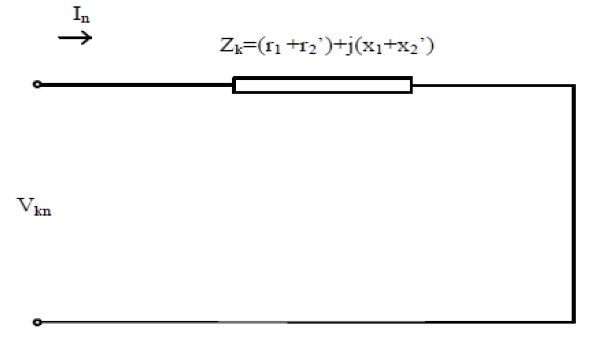
Transformer Parameters and Equivalent Circuit (Short Circuit Transformer)
Short circuit voltage is one of the most important parameters of a transformer. It is indicated as %Uk (or %Z) on the transformer’s technical data sheet.
Short circuit voltage (%Uk) is the voltage that must be applied to the primary winding (with the secondary winding short-circuited) to produce the rated nominal current in the primary. This value directly determines the maximum short-circuit current that will flow in case of a fault on the secondary side and is critical for protection device selection.
Transformer efficiency is mainly affected by two types of losses:
No-load losses (Iron / Core losses): Caused by hysteresis and eddy currents in the magnetic core.
Load losses (Copper losses): Caused by the resistance of the windings under load.
Reducing these losses is key to achieving high transformer efficiency.
Short Circuit Transformer Current Calculation
The short-circuit current (Ik) of a transformer can be calculated as:
Ik = In / (%Uk / 100)
Where In is the rated nominal current of the transformer.
This calculation must be performed separately for both primary and secondary sides because voltage and current ratings differ.
Transformer Short Circuit Calculation
Transformer Equivalent Circuit
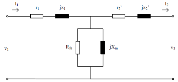
Because the primary and secondary windings are magnetically coupled but electrically isolated, we use an equivalent circuit referred to one side (usually the primary).
The most common model is the T-type equivalent circuit referred to the primary side. It includes:
r1, x1 → Primary winding resistance and leakage reactance
r’2, x’2 → Secondary winding resistance and leakage reactance referred to primary
Rfe → Core loss resistance
Xm → Magnetizing reactance
These parameters are determined through short circuit test and open circuit (no-load) test.
Transformer Equivalent Circuit
Short Circuit Test (Short Circuit Transformer Test)
In the short circuit test, the secondary winding is short-circuited and a reduced voltage is applied to the primary until rated current flows. This test gives the copper losses and the total impedance of the transformer.
Open Circuit (No-Load) Test
In the open circuit test, the secondary is left open and rated voltage is applied to the primary. This test determines the core losses (iron losses), magnetizing current, and the values of Rfe and Xm.
Apparent, Active, and Reactive Power
Apparent Power (S) = V × I
Active Power (P) = S × cosφ
Reactive Power (Q) = S × sinφ
Understanding transformer parameters and the equivalent circuit is essential for proper transformer selection, protection coordination, and system short-circuit analysis.
Looking for Transformer for your project?
Looking for detailed technical information on transformer parameters, equivalent circuit, short circuit voltage, and short circuit calculations? We provide expert support for distribution and power transformers tailored to your needs.
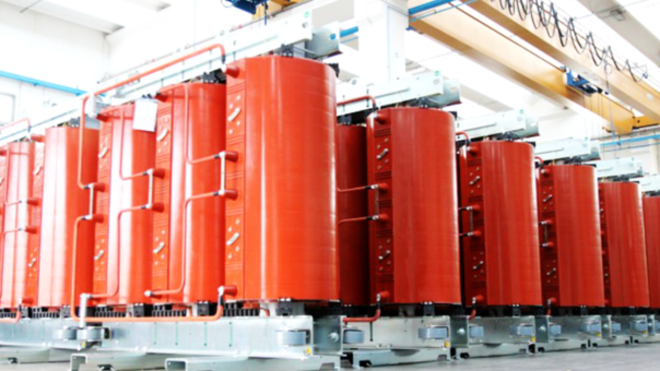
A dry type transformer is a medium voltage power transformer that insulates its windings with solid epoxy cast resin instead of mineral oil, relying on ambient or fan-assisted air for cooling rather than liquid dielectric. Because it carries no flammable insulating fluid, it is the reference technology for indoor substations where fire safety, personnel protection, and low maintenance outweigh the marginal cost premium over oil-filled units. This hub article walks through construction, cooling and insulation classes, sizing logic, applicable IEC and national standards, typical applications, and a side-by-side comparison with oil type transformers, so that procurement and design engineers across the Middle East and Gulf region including Egypt and Saudi Arabia, North Africa, CIS countries, and Sub-Saharan Africa can specify the correct unit with confidence.
Dry Type Transformer — schematic.
What Is a Dry Type Transformer? Definition and Core Principle
In a dry type transformer — also called a cast resin dry type transformer or dry type power transformer — the high voltage windings are cast under vacuum in epoxy resin, forming a solid, void-free insulation block around the conductor. This vacuum-casting process gives the winding excellent dielectric strength, mechanical robustness, and resistance to moisture and chemical attack, without any need for oil-filled tanks, gaskets, or bushings that could leak.
The low voltage winding is produced either with the same cast-resin technique or with prepreg (pre-impregnated) insulation technology, depending on the manufacturer’s design. Unlike oil type units, the windings are not enclosed inside a sealed tank; they remain open to the surrounding atmosphere. This open construction allows straightforward visual inspection of the winding surface during maintenance and also improves natural heat dissipation because the resin block is in direct contact with the cooling air stream.
Selection reference.
Dry Type vs Oil Type Transformer: Key Differences
Power transformers are broadly split into two families: oil type transformers and dry type transformers. Oil type units use mineral oil as both the dielectric insulation medium and the cooling fluid. Oil cooling performs very well outdoors and can support compact designs, but the flammable nature of mineral oil introduces an inherent risk of fire and explosion in the event of an internal fault, and any oil leak carries environmental contamination risk.
Dry type transformers eliminate this fluid entirely. Because there is no oil to leak, ignite, or contaminate soil and groundwater, the fire and explosion hazard associated with liquid-filled units is designed out of the equation. The trade-off is manufacturing cost: cast resin dry type transformers are generally more expensive to produce than equivalent oil-filled units, but this premium is routinely justified wherever the installation is indoors and shares space with people — hospitals, schools, commercial towers, and transport infrastructure.
Comparison Table: Dry Type vs Oil Type Transformer
Criterion
Dry Type Transformer
Oil Type Transformer
Insulation medium
Epoxy cast resin (HV); resin or prepreg (LV)
Mineral oil
Cooling medium
Air (natural or forced)
Mineral oil (natural or forced circulation)
Fire/explosion risk
Self-extinguishing, flame-retardant design
Present, due to flammable oil
Leakage / environmental risk
None (no oil)
Oil leak can cause environmental pollution
Typical location
Indoor: hospitals, schools, malls, metro, data centers, high-rise, airports
Predominantly outdoor
Maintenance
Low, open windings allow visual inspection
Periodic oil sampling/testing needed
Relative manufacturing cost
Higher
Lower
Cooling System: AN and AF Configurations
Dry type transformers rely exclusively on air rather than any liquid medium for cooling, and two configurations are standardized in practice:
AN (Air Natural): heat is removed purely by natural convection around the resin-cast windings, with no mechanical assistance.
AF (Air Forced): fans mounted at the bottom of the transformer actively push air through the winding ducts, increasing the thermal transfer rate.
Switching from AN to AF mode is not just a cooling upgrade — it is a genuine capacity boost. When the fans are activated, the same transformer can accept up to 40% additional load compared with its natural-cooling rating. This AN/AF flexibility lets a single physical unit cover two nameplate ratings, which is valuable where a facility’s load profile is expected to grow after commissioning.
Fan activation is not manual — temperature sensors embedded directly in the windings continuously track winding hot-spot temperature and automatically trigger the fans through a relay control system whenever a threshold is reached. This closed-loop thermal management protects the resin insulation from thermal aging while ensuring fans only run when genuinely needed, saving auxiliary power and extending fan service life.
Enclosure and Protection (IP) Ratings
The as-manufactured protection class for a standard cast resin dry type transformer is IP00, meaning the winding assembly itself has no built-in ingress protection and is intended to sit inside a switchgear room or dedicated enclosure. Where the installation is outdoors, or the indoor environment is humid or dusty, the transformer must be fitted inside a protective enclosure rated IP21, IP23, or IP31 to keep out solid objects and dripping/spraying moisture. Selecting the correct enclosure rating is as important as selecting the transformer itself — an IP00 unit placed in an unprotected outdoor yard will fail prematurely regardless of its electrical design margins.
Insulation Classes and IEC 60076-11 Environmental Categories
Cast resin dry type transformers are built with either F class insulation, rated for a maximum operating temperature of 155°C, or the higher-performance H class insulation, rated for 180°C. The choice between F and H class affects both the thermal aging margin of the winding and, in some designs, the achievable overload headroom.
Beyond thermal class, IEC 60076-11 defines three separate classification axes for dry type transformers: environmental class, climatic class, and fire behavior class. The most commonly specified combination in the field is E2–C2–F1.
Environmental Class (E)
Class
Meaning
E0
Operates in a clean, dry room; pollution ignored, no condensation.
E1
Operates in an environment with low condensation and pollution.
E2
May be exposed to both condensation and high pollution.
Climatic Class (C)
Class
Meaning
C1
Cannot be energized below -5°C; can only be transported and stored down to -25°C.
C2
Can be energized, transported, and stored down to -25°C.
Fire Resistance Class (F)
Class
Meaning
F0
Probability of fire is not at the expected level; no condition for limiting the hazard.
F1
Exposed to fire possibility; reduced flammability is mandatory, and any fire must self-extinguish within a specified time.
For projects in humid coastal Gulf sites or high-pollution industrial zones, specifying E2 is typically the safe default, while C1 vs C2 should be matched to the actual minimum ambient/storage temperature the unit will experience on site.
Sizing and Power Ratings
Dry type transformers are manufactured across a wide power range, commonly starting at 250 kVA and extending up to 8 MVA. Within that range, the ratings most frequently selected on real projects cluster around 1600 kVA and 2500 kVA, reflecting typical building and industrial feeder loads.
A practical constraint arises when a dry type transformer is to be installed inside a concrete kiosk substation: ventilation and physical space inside the enclosure typically cap the recommended power at 1250 kVA, in line with TEDAŞ (Turkish state distribution) specifications. This is a useful rule of thumb for any project using compact prefabricated kiosk substations, even outside Turkey, since the underlying constraint — restricted air exchange volume — is a physical one rather than a purely regulatory one.
Selection Criteria Checklist
When specifying a dry type transformer for an indoor or semi-outdoor MV/LV substation, the engineer should confirm the following in order:
Power rating — select within the 250 kVA–8 MVA production range, biasing toward proven 1600/2500 kVA platforms where the load profile fits, or de-rating to 1250 kVA maximum for kiosk installations.
Cooling mode — decide between AN-only operation or AN/AF dual rating if a 40% future load growth allowance through forced-air cooling is required.
Insulation thermal class — F class (155°C) for standard duty, or H class (180°C) where higher thermal margin or compact design is preferred.
Environmental/climatic/fire class per IEC 60076-11 — E2-C2-F1 is the common baseline for humid, polluted, or fire-sensitive installations.
Enclosure IP rating — IP00 for protected indoor rooms; IP21/IP23/IP31 enclosure required for outdoor or humid conditions.
Governing technical specification — confirm compliance with the applicable national distribution utility specification and IEC 60076-11.
Applications
Because dry type transformers eliminate the flammable oil hazard, they are the default choice wherever transformers must sit close to people or sensitive equipment: hospitals, schools, shopping malls, metro stations, data centers, high-rise buildings, airports, and general commercial complexes. Across the Middle East and Gulf region including Egypt and Saudi Arabia, North Africa, CIS countries, and Sub-Saharan Africa, this same logic applies to any indoor substation embedded in an occupied building, transit facility, or dense urban plot where fire code compliance and space constraints make oil-filled units impractical.
Standards and Compliance
Internationally, dry type transformers are designed, tested, and classified according to IEC 60076-11, which governs the environmental (E), climatic (C), and fire behavior (F) classification system described above. In Turkey specifically, any dry type transformer supplied for a project that will be handed over to a distribution company must additionally comply with the TEDAŞ-MLZ/99-031.B technical specification. Buyers outside Turkey should verify the equivalent local distribution-utility specification while treating IEC 60076-11 as the common international baseline. Leading global manufacturers such as ABB and Schneider Electric offer dry type transformer lines with published technical datasheets and catalogue documentation that reference this same IEC framework.
A dry type transformer is used for indoor MV/LV power distribution wherever fire safety and human proximity are critical, including hospitals, schools, shopping malls, metro stations, data centers, high-rise buildings, and airports.
How is a dry type transformer different from an oil type transformer?
A dry type transformer insulates and cools its windings with epoxy cast resin and air, eliminating the oil found in oil type transformers and, with it, the associated fire, explosion, and leakage risks — at the cost of a higher manufacturing price.<!– 🔴 iddia: dry type transformers eli
Looking for Dry-Type Transformers?
Looking for high-quality dry-type transformers? We provide expert engineering support and reliable products for all your medium voltage needs.