
An arc flash study is the engineering analysis that quantifies the incident energy and safe working boundaries released by a potential internal arcing fault in electrical equipment, so that personnel protective equipment (PPE), labeling, and switchgear design can be correctly specified. For medium-voltage (MV) switchgear, this study combines a short-circuit current calculation with an arc-energy model to determine how much thermal energy a worker could be exposed to at a given working distance and fault-clearing time. This guide walks through the calculation method step by step, with a fully worked numerical example, a comparison table, selection guidance, and the governing IEC/IEEE standards. It is written for utility, EPC, and industrial engineers specifying or auditing MV switchgear across the Middle East and Gulf region (including Egypt and Saudi Arabia), North Africa, CIS countries, and Sub-Saharan Africa, where new substations and retrofit projects increasingly require documented arc flash risk assessments as part of tender specifications.
Why the arc flash study matters
An internal arcing fault inside MV switchgear releases energy far beyond that of a normal bolted short circuit because the arc itself adds resistance and radiates heat, light, and pressure into the surrounding air. Unlike low-voltage arc flash incidents, MV arcing faults can sustain very high currents for the full duration of the protection relay‘s clearing time, so the resulting incident energy at typical working distances can be severe. The purpose of the study is threefold: (1) to select the correct PPE category and boundary distances for switching, racking, and testing operations; (2) to justify design mitigation such as arc-resistant (IAC-classified) switchgear enclosures, arc-flash relays, or remote racking; and (3) to support relay coordination decisions that reduce clearing time, which has a direct, near-linear effect on incident energy.
The calculation method
An arc flash study for MV switchgear is performed in three sequential steps.
Step 1 — Bolted (three-phase) short-circuit current, per IEC 60909. The available bolted fault current at the switchgear busbar is calculated from the source impedance (utility grid, generator, and transformer impedances reflected to the bus voltage), following the IEC 60909 short-circuit calculation method. This gives the initial symmetrical short-circuit current, Ik″, which is the starting point for the arc flash model.
Step 2 — Arcing current. An arcing fault draws less current than a bolted fault because the arc itself introduces impedance. Empirical arc flash models (notably IEEE 1584) derive an arcing current, Ia, as a function of the bolted fault current, system voltage, and the electrode gap of the equipment. As a general engineering rule of thumb used in MV arc flash screening, the arcing current is commonly on the order of 85–95% of the bolted fault current, though the exact ratio depends on voltage class and equipment geometry and should be taken from the applicable arc-current equation rather than assumed.
Step 3 — Incident energy. Incident energy (typically expressed in cal/cm²) is calculated from the arcing current, the total protection clearing time (relay pickup + breaker interrupting time), the working distance from the potential arc source, and an equipment/enclosure correction factor. The relationship is approximately proportional to arcing current, proportional to clearing time, and inversely proportional to the square of the working distance — which is why reducing clearing time and increasing working distance are the two most effective mitigation levers available to the design engineer.
Internal reference material on protection relay coordination is available on our protection relay hub page, and on transformer impedance data on our distribution transformer hub page, both of which feed directly into Steps 1 and 3 above.
Worked example
Consider an 11 kV MV switchboard fed through a 1000 kVA distribution transformer, with an upstream grid fault level of 500 MVA at the 11 kV busbar.
Rated current of the transformer secondary: I = S / (√3 × V) = 1,000,000 / (1.732 × 11,000) ≈ 52.5 A
Bolted fault current at the 11 kV bus (from grid fault level): Ibf = Ssc / (√3 × V) = 500,000,000 / (1.732 × 11,000) ≈ 26,247 A ≈ 26.2 kA
Estimated arcing current (using an illustrative 90% ratio for MV switchgear, per the general relationship described in Step 2 above): Ia ≈ 0.90 × 26.2 kA ≈ 23.6 kA
Clearing time: assume the protection relay and circuit breaker combination clears the fault in 0.3 seconds (typical for a coordinated MV feeder protection scheme with time-graded overcurrent settings).
Working distance: assume a standard 610 mm (24 in) working distance for a worker at the switchgear front panel during a racking or switching operation.
Using the general IEEE 1584 relationship that incident energy scales with arcing current and time and inversely with the square of working distance, an illustrative incident energy for this scenario — calculated per the full IEEE 1584-2018 equipment-class-specific formula — would need to be run through the standard’s published coefficients for the exact enclosure type and gap distance; the example above illustrates only the input variables an engineer must gather (bolted fault current, arcing current, clearing time, and working distance) before that formula is applied. The key takeaway is that halving the clearing time — for example, from 0.3 s to 0.15 s through faster relay coordination — roughly halves the resulting incident energy, while doubling the working distance reduces it by roughly a factor of four.
Worked example — summary table
| Parameter | Symbol | Formula / Basis | Value |
|---|---|---|---|
| System voltage | V | Given | 11 kV |
| Transformer rating | S | Given | 1000 kVA |
| Transformer rated current | I | S/(√3×V) | ≈ 52.5 A |
| Upstream fault level | Ssc | Given | 500 MVA |
| Bolted fault current | Ibf | Ssc/(√3×V), per IEC 60909 | ≈ 26.2 kA |
| Estimated arcing current | Ia | ≈0.90 × Ibf (illustrative ratio) | ≈ 23.6 kA |
| Protection clearing time | t | Relay + breaker interrupting time | 0.3 s (example) |
| Working distance | D | Standard front-panel exposure | 610 mm |
| Incident energy | E | Per IEEE 1584 equipment-class equation | Requires full IEEE 1584 formula with enclosure/gap coefficients |
Selection criteria and common pitfalls
Use arcing current, not bolted current, for the energy calculation. Using the bolted fault current directly (skipping Step 2) overstates or understates incident energy depending on system characteristics and is a frequent audit finding.
Get the clearing time right, including relay pickup and breaker interrupting time. Because incident energy scales roughly linearly with clearing time, an arc flash study performed with outdated relay settings after a protection upgrade will misstate the actual hazard — the study must be re-run whenever protection coordination changes.
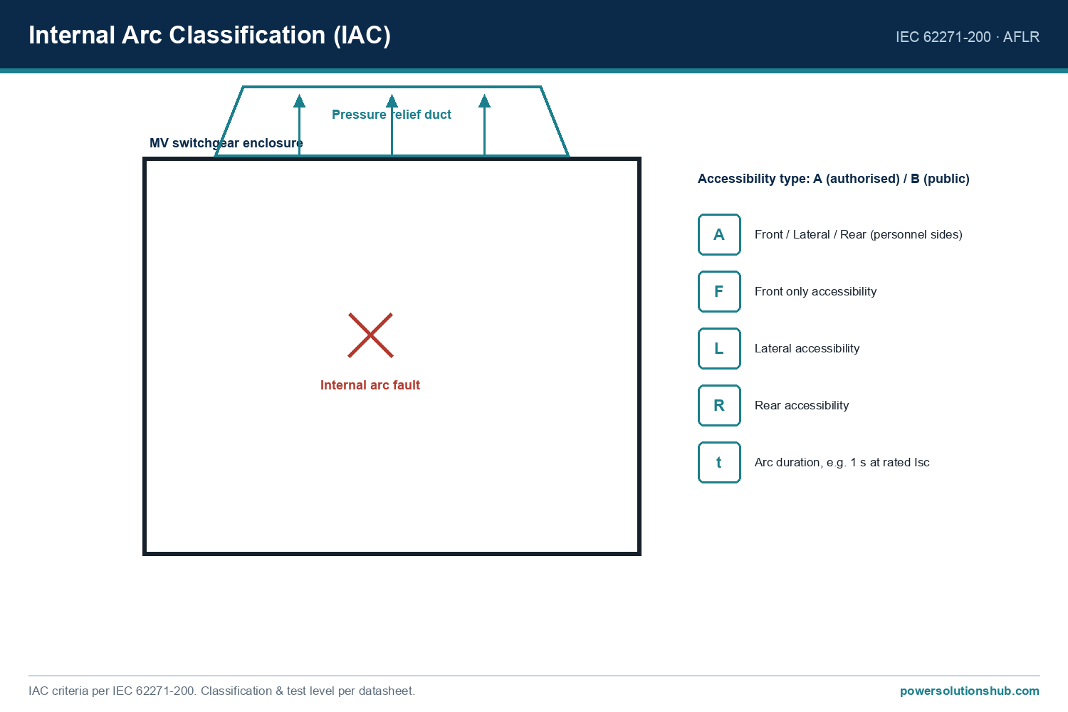
Specify arc-resistant (IAC-classified) switchgear where personnel access is required during energized conditions. Internal arc classification (IAC) testing under IEC 62271-200 verifies that a switchgear enclosure can contain and vent the effects of an internal arcing fault away from the operator’s normal standing position, which is a design mitigation independent of — but complementary to — the PPE-based arc flash study.
Consider arc-flash detection relays for high-energy applications. Optical or pressure-based arc detection can cut clearing time to a fraction of a standard overcurrent relay’s response, delivering the largest single reduction in incident energy achievable at the protection level.
Re-validate the study after any system change. Adding generation, changing transformer impedance, reconfiguring bus ties, or upgrading protection settings all change the bolted fault current, the arcing current, or the clearing time — any of which invalidates a previous study.
Match working distance assumptions to actual operating tasks. Racking a withdrawable circuit breaker, inserting test plugs, or opening a cable compartment door each expose personnel at different distances; the study should reflect the closest realistic exposure for each task, not a single generic distance.
Governing standards
The arc flash calculation methodology itself is defined by IEEE 1584 (Guide for Performing Arc Flash Hazard Calculations), which provides the empirical equations for arcing current and incident energy referenced in this guide. The upstream short-circuit current used as an input is calculated per IEC 60909 (Short-circuit currents in three-phase AC systems). Where the switchgear enclosure itself is intended to contain and vent an internal arcing fault, the relevant equipment standard is IEC 62271-200 (AC metal-enclosed switchgear and controlgear for rated voltages above 1 kV and up to and including 52 kV), which defines the internal arc classification (IAC) test procedure and accessibility types. Related testing guidance for internal arc effects is also addressed in IEC 61641. Engineers should confirm which of these standards is referenced in the project’s technical specification, since utilities and EPC contractors in different regions may cite different editions or combinations.
For background on the switchgear types these studies are typically performed on, see our [medium voltage switchgear](https://powersolutionshub.com/what-is-mv-switchgear-medium-voltage-switchgear/) hub page.
Related guides
See also our guides on gas-insulated switchgear, ring main units and metal-clad switchgear.
What is the difference between an arc flash study and a short-circuit study?
A short-circuit study (per IEC 60909) calculates the available bolted fault current at each bus in the system. An arc flash study uses that fault current as an input, together with arcing current, clearing time, and working distance, to calculate the incident energy a worker could be exposed to — it is a downstream analysis that depends on the short-circuit study being current and accurate.
Does arc flash risk apply to MV switchgear or only to low-voltage panels?
Arc flash hazards apply across all voltage classes, including MV switchgear. In fact, MV arcing faults can sustain higher fault currents for longer durations than typical LV panels, which is why arc-resistant (IAC) switchgear design and arc-flash relay protection are commonly specified for MV applications with routine personnel access.
How often should an arc flash study be updated?
The study should be reviewed whenever the electrical system changes in a way that affects fault current or clearing time — new generation or transformers, protection relay setting changes, bus reconfiguration, or utility fault-level revisions — and periodically reviewed as part of routine electrical safety audits even without known changes.
What is IAC classification and how does it relate to arc flash studies?
Internal Arc Classification (IAC), defined under IEC 62271-200, is a switchgear design verification confirming the enclosure can withstand and vent an internal arcing fault without endangering an operator standing in a defined accessibility zone. It is a complementary mitigation to the arc flash study: the study quantifies residual risk and PPE requirements, while IAC-rated equipment reduces the underlying hazard at its source.
Can reducing the protection clearing time reduce arc flash risk without changing the switchgear?
Yes. Because incident energy is approximately proportional to clearing time, faster protection response — through optimized relay coordination, differential protection, or dedicated arc-flash detection relays — can significantly reduce calculated incident energy without any change to the switchgear enclosure itself.
Who typically performs an arc flash study for MV switchgear?
Arc flash studies are typically performed by protection and power systems engineers using dedicated short-circuit and arc-flash calculation software that implements the IEEE 1584 equations, supported by accurate single-line diagrams, transformer impedance data, and relay coordination settings from the project’s protection study.
What working distance should be used for MV switchgear when no site-specific data is available?
In the absence of manufacturer- or site-specific data, engineers commonly use standard reference working distances associated with typical operator positions during switching, racking, or test-plug insertion tasks, as defined in the arc flash calculation standard being applied; these distances should always be verified against the actual task and equipment geometry rather than assumed by default.
Looking for medium voltage switchgear?
Looking for high-quality medium voltage switchgear? We provide expert engineering support and reliable products for all your medium voltage needs.
For quotations and requests: info@electricistanbul.com
WhatsApp: +90 501 076 69 91