
Earth fault protection in MV networks is the set of relaying and earthing measures used to detect, measure, and clear insulation failures between a live conductor and earth in a medium-voltage system before they escalate into equipment damage, fire, or safety hazards. This guide walks through the underlying physics of earth faults, the neutral earthing methods that shape fault current magnitude, the core relay formulas, a fully worked numerical example, a selection/comparison table, and the governing IEC standards — written for engineers specifying or commissioning protection on ring main units, primary substations, and industrial MV switchgear across the Middle East and Gulf region (including Egypt and Saudi Arabia), North Africa, CIS, and Sub-Saharan Africa markets.
Unlike phase-to-phase short circuits, earth faults are often low-current, high-impedance events that standard overcurrent protection cannot reliably detect — which is precisely why dedicated earth fault (residual/zero-sequence) protection exists as a separate protection function in every properly engineered MV switchgear and [protection relay](/what-is-a-medium-voltage-protection-relay-mv-protection-relay/) scheme.
Why Earth Fault Protection Matters
Most insulation failures in MV cable systems, transformers, and switchgear begin as single-phase-to-earth faults. If left undetected, a sustained earth fault can:
- Escalate into a phase-to-phase or three-phase fault, multiplying the destructive energy released.
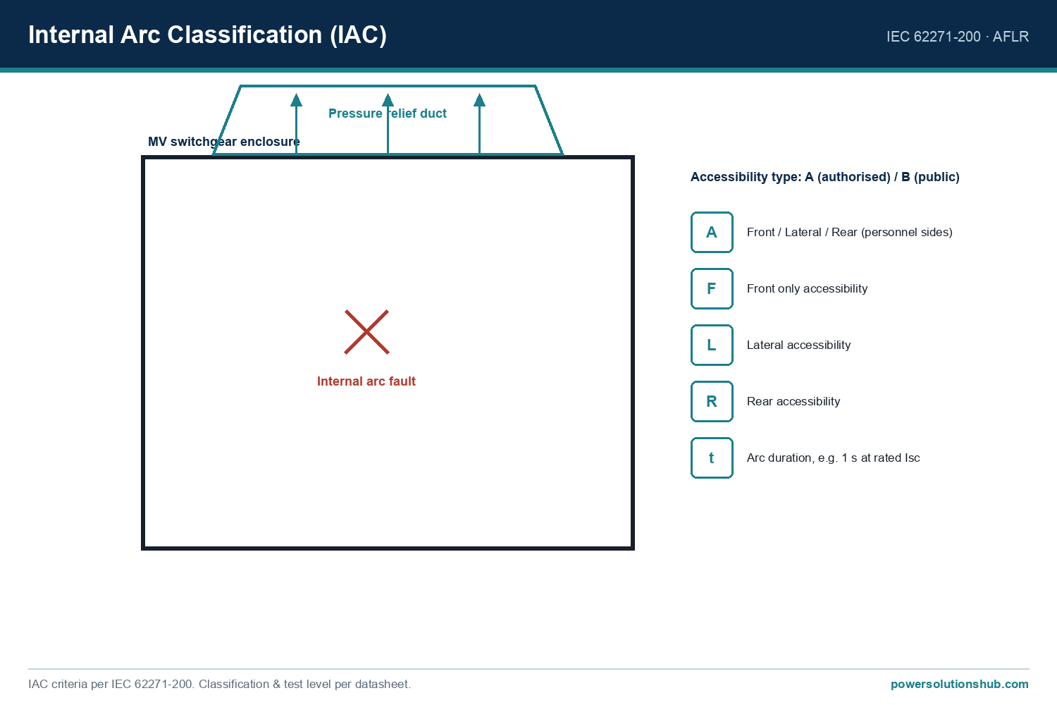
- Produce sustained arcing that damages busbars and can trigger an internal arc event inside switchgear.
- Create step-and-touch voltage hazards for personnel if earthing grids are inadequately designed.
- Cause sustained neutral displacement in unearthed or compensated systems, stressing insulation on healthy phases.
Because fault current magnitude in an earth fault depends heavily on how the system neutral is earthed — solidly, through a resistor, through a reactor (Petersen coil), or left isolated — earth fault protection must be engineered together with the earthing philosophy, not as an afterthought bolted onto phase overcurrent relays.
The Method: How Earth Fault Current Is Detected and Measured
1. Zero-sequence (residual) current principle
In a healthy three-phase system, the vector sum of the three phase currents is zero:
I_R + I_S + I_T = 0
When an earth fault occurs, this balance is broken and a residual current I_e flows:
I_e = I_R + I_S + I_T ≠ 0
This residual current is what earth fault relays detect, typically measured by one of two methods:
- Residual connection of three separate phase CTs (summing the secondary currents), or
- Core-balance CT (CBCT / zero-sequence CT), where all three phases pass through a single toroidal core so the CT output is directly proportional to the earth fault current, giving much higher sensitivity for low-magnitude faults.
2. Fault current magnitude depends on neutral earthing
The earthing method sets the theoretical ceiling on earth fault current:
- Solidly earthed neutral — fault current can approach or exceed the three-phase short-circuit level; fast, sensitive protection is essential because the fault energy is high.
- Resistance earthing — a neutral earthing resistor (NER) deliberately limits fault current to a controlled, pre-selected value (commonly designed in the range of tens to a few hundred amperes for MV systems), improving selectivity and lowering damage energy.
- Reactance/Petersen coil (resonant) earthing — a tuned reactor cancels the capacitive fault current of the network, allowing many single-phase-to-earth faults to self-extinguish without tripping.
- Isolated (unearthed) neutral — fault current is limited only by the system’s own phase-to-earth capacitance; magnitudes are typically low, but sustained neutral displacement raises stress on healthy-phase insulation, so an alarm-only or time-delayed strategy is common.
3. The basic relay formula
An earth fault (50N/51N) relay operates when the measured residual current exceeds a set pickup, for a defined time based on the selected curve:
I_e (measured) ≥ I_set → trip after time t
where, for definite-time protection:
t = t_set (constant)
and for inverse-time (IDMTL) curves, per IEC 60255-151:
t = (k × TMS) / [(I_e / I_set)^α − 1]
with k and α depending on the selected curve family (standard inverse, very inverse, extremely inverse), and TMS the time multiplier setting used for coordination with upstream/downstream devices.
Worked Example: Sizing and Setting an Earth Fault Relay
Consider a distribution feeder supplied from an 11 kV busbar through a 1000 kVA transformer protected by an MV circuit breaker with a core-balance CT of ratio 100/1 A feeding a numerical relay.
Step 1 — Rated feeder current
For a 1000 kVA transformer at 11 kV:
I = S / (√3 × V) = 1,000,000 / (1.732 × 11,000) ≈ 52.5 A
Step 2 — Choose the earth fault pickup
Earth fault settings are normally set well below the phase rated current because expected earth fault current is much smaller than load current (especially on resistance-earthed or isolated systems). For example, choosing a pickup at 20% of the CT primary rating:
I_set = 0.20 × 100 A = 20 A (primary), i.e. 0.20 A on the relay’s 1 A CT secondary.
Step 3 — Check against expected fault current
Suppose the network uses resistance earthing sized to limit earth fault current to 300 A primary. The relay’s 20 A pickup gives a comfortable margin (factor ≈15) above the noise/CT-error floor while remaining far below the 300 A fault level, so the relay will detect the fault decisively.
Step 4 — Time setting for coordination
Using an IDMTL standard inverse curve with k = 0.14 and α = 0.02 (IEC 60255-151 standard inverse constants), and assuming a downstream device must clear first with an intended relay operating time of about 0.4 s at 300 A fault current:
I_e / I_set = 300 / 20 = 15
t = (0.14 × TMS) / (15^0.02 − 1)
15^0.02 ≈ 1.0572, so denominator ≈ 0.0572
t = (0.14 × TMS) / 0.0572 = 2.448 × TMS
Solving for TMS to get t ≈ 0.4 s:
TMS = 0.4 / 2.448 ≈ 0.163
This TMS value (rounded to a practical relay step, e.g. 0.15–0.2) would then be entered into the relay together with the pickup current, and verified against the upstream device’s own earth fault curve to confirm discrimination margins are met across the full fault-current range.
(All figures above are illustrative worked-example arithmetic derived from stated formulas, not manufacturer ratings.)
Selection & Comparison: Earthing Method vs Protection Strategy
| Earthing method | Typical fault current behaviour | Protection approach | Key benefit |
|---|---|---|---|
| Solidly earthed | High fault current, fast rise | Fast instantaneous + IDMTL backup | Simple, well-defined fault level |
| Resistance earthed (NER) | Fault current limited to a designed value | Sensitive definite-time or IDMTL on residual CT | Reduces damage energy, easier coordination |
| Reactance / Petersen coil | Near-zero residual current (compensated) | Wattmetric / directional earth fault relay | Many faults self-clear, high service continuity |
| Isolated (unearthed) | Low, capacitance-limited current | Alarm on neutral displacement voltage, then locate fault | Continuity of supply on first fault |
Selection Criteria and Common Pitfalls
- Match relay sensitivity to earthing method. A CBCT-based earth fault relay tuned for a solidly earthed system will be far too coarse for an isolated or Petersen-coil network, where fault currents are orders of magnitude smaller.
- Verify CT knee-point and accuracy class, especially for core-balance CTs used at low pickup settings — CT saturation or poor accuracy at low current directly undermines sensitivity.
- Coordinate time-current curves between incoming, feeder, and transformer protection devices so the relay closest to the fault always operates first (selectivity), reducing unnecessary outages upstream.
- Consider directional earth fault protection on interconnected or ring/loop-fed networks, where fault current can flow in either direction depending on fault location — a non-directional relay may mis-operate.
- Account for standing/charging current on long cable networks in isolated or compensated systems; unusually long cable runs can raise the natural capacitive earth fault current enough to desensitize a poorly set relay.
- Re-verify settings after any network reconfiguration (new feeders, transformer changes, or switchgear additions), since fault levels and CT ratios may shift.
- Coordinate with transformer neutral earthing design at the point of supply — the earthing method is usually fixed at the transformer, not the feeder relay.
Governing Standards
Earth fault (and general overcurrent/earth-fault) protection relay characteristics, including standard inverse, very inverse and extremely inverse time-current curves, are defined in IEC 60255-151 (measuring relays and protection equipment — functional requirements for over/under current protection). Coordination of protection and earthing arrangements within MV switchgear installations is generally referenced against IEC 62271 series requirements for the switchgear itself, while system earthing philosophy for MV distribution networks is commonly guided by IEC and national utility earthing codes appropriate to the specific network. Project-specific earthing and protection studies should always confirm the applicable national or utility standard for the installation.
Related guides
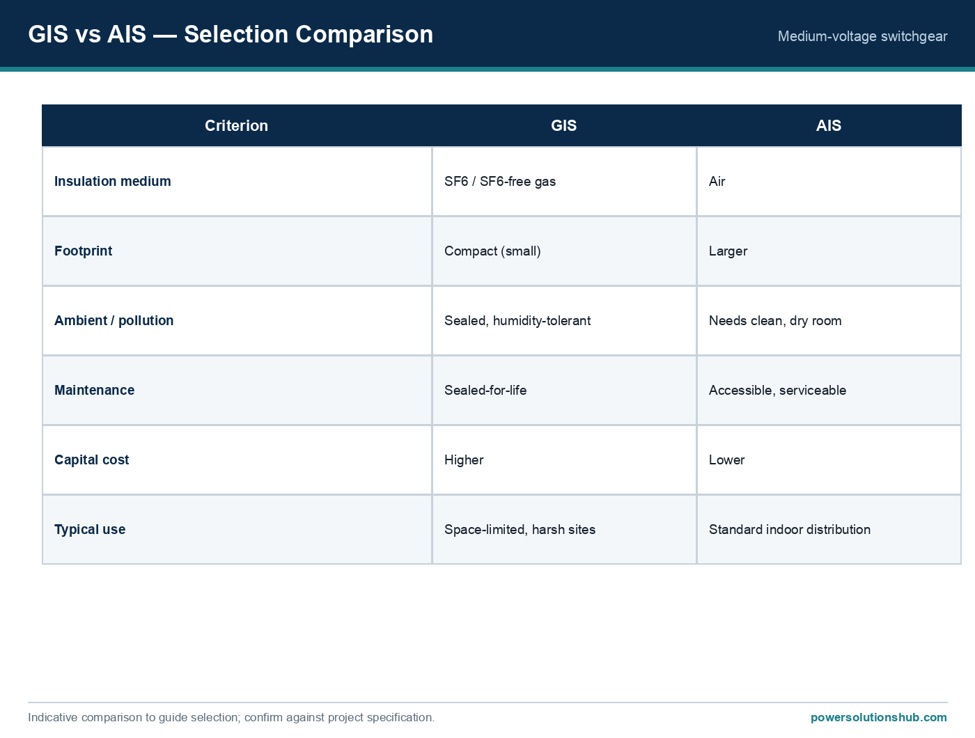
See also our guides on gas-insulated switchgear, metal-clad switchgear and air-insulated switchgear.
What is the difference between earth fault protection and overcurrent protection?
Overcurrent protection (50/51) responds to excessive phase current from overloads or phase-to-phase faults, while earth fault protection (50N/51N) specifically detects the residual/zero-sequence current that appears only when current leaks to earth, which can be far smaller than a phase fault current and would otherwise go undetected by phase relays alone.
Why does neutral earthing method affect relay settings?
The earthing method — solid, resistance, reactance (Petersen coil), or isolated — determines the theoretical magnitude of earth fault current available in the network, so the relay’s pickup, time delay, and directional requirements must all be engineered around the specific earthing scheme in use.
What is a core-balance CT and why is it used for earth fault protection?
A core-balance CT (CBCT) passes all three phase conductors through a single toroidal core so its secondary output is directly proportional to the residual (earth fault) current, offering much higher sensitivity than summing three separate phase CTs, especially important for low-magnitude faults on resistance-earthed or isolated systems.
When is directional earth fault protection needed?
Directional earth fault relays are needed on interconnected, ring, or parallel-fed MV networks where fault current can flow toward the relay from either direction depending on fault location, since a non-directional relay could trip the wrong breaker or fail to discriminate correctly.
What is a wattmetric earth fault relay and when is it used?
A wattmetric (or “zero-sequence power”) earth fault relay measures the real power component of the residual current and voltage, which is particularly effective on compensated (Petersen coil) networks where the reactive residual current is largely cancelled by the coil, leaving only a small resistive component to detect.
Can earth fault protection alone protect against all MV fault types?
No — earth fault protection specifically targets phase-to-earth faults and must work alongside phase overcurrent, differential, and (where applicable) restricted earth fault protection to provide complete coverage of all fault types on transformers, feeders, and switchgear.
How should earth fault relay settings be verified after commissioning?
Settings should be checked with a primary or secondary injection test confirming pickup current, operating time at multiple fault-current multiples, and directional polarity (if applicable), and re-verified whenever the network’s earthing arrangement, transformer configuration, or feeder topology changes.
Looking for medium voltage switchgear?
Looking for high-quality medium voltage switchgear? We provide expert engineering support and reliable products for all your medium voltage needs.
For quotations and requests: info@electricistanbul.com
WhatsApp: +90 501 076 69 91