
A current transformer (CT) is an instrument transformer that reproduces primary system current as a proportionally scaled, safe secondary signal — typically 5 A or 1 A — for use by protection relays, meters, and measuring instruments. Correct CT sizing means selecting the right rated primary current, ratio, burden capability, and accuracy class so the connected relay or meter sees an undistorted, sufficiently accurate signal across the full operating range, from normal load current up to fault current. This guide walks through the underlying formulas, a fully worked numerical example, a comparison table of protection versus metering classes, and the common sizing pitfalls that cause nuisance tripping or missed operations in the field. The same principles apply whether the installation is a compact ring main unit, a large air-insulated switchgear lineup, or a substation retrofit project across the Middle East and Gulf (including Egypt and Saudi Arabia), North Africa, CIS, and Sub-Saharan Africa markets that Power Solutions Hub serves.
Why CT Sizing Matters
An undersized or mis-specified CT can saturate during a fault, distorting the secondary waveform exactly when the protection relay most needs an accurate signal. An oversized CT, on the other hand, may deliver a secondary current too small relative to its rated burden to be measured accurately at normal load, degrading metering precision and revenue accuracy. Because CTs sit at the boundary between the primary power system and the secondary protection/metering system, every downstream relay setting, energy metering calculation, and fault-clearing decision depends on the CT delivering a faithful, linearly scaled current signal within its design limits.
The Core Formulas
1. CT ratio. A CT is specified by its rated transformation ratio, expressed as primary current to secondary current, for example 400/5 A or 1000/1 A. The ratio should be selected so that the expected maximum continuous load current runs at roughly 60–100% of the CT’s rated primary current — running a CT permanently at a very low fraction of its rated primary current degrades accuracy at normal load.
2. Rated burden. Burden is the total impedance (in VA at rated secondary current, or in ohms) that the CT secondary circuit must drive — this includes relay/meter input impedance, terminal wiring resistance, and connector losses. The formula is:
Burden (VA) = I_sec² × Z_burden
where I_sec is the rated secondary current (A) and Z_burden is the total secondary loop impedance (Ω).
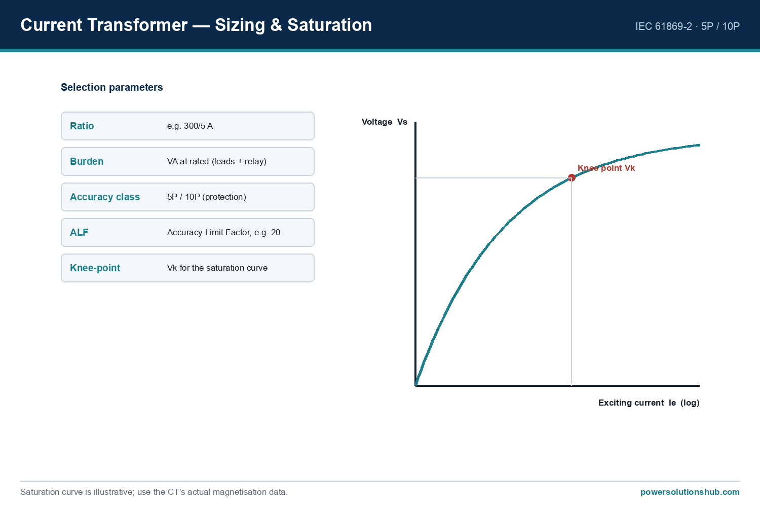
3. Accuracy Limit Factor (ALF) for protection CTs. ALF defines the multiple of rated primary current up to which the CT maintains its stated accuracy (composite error) before significant saturation occurs. A protection-class CT with ALF 10 and accuracy class 5P (per IEC 61869-2) is expected to remain within its stated composite error limit up to 10 times rated primary current.
4. Rated Equivalent Limiting Secondary EMF (Vk-type checks) and knee-point voltage are used for more detailed saturation studies (particularly with differential and unit protection schemes), but the ALF/burden method below is sufficient for the great majority of MV feeder and transformer protection sizing tasks.
5. Cable burden formula. For secondary wiring runs from the CT to the relay panel:
Z_cable = ρ × (2L) / A
where ρ is the resistivity of copper conductor, L is the one-way cable length (m), and A is the conductor cross-sectional area (mm²). The factor of 2 accounts for the go-and-return conductor loop.
Worked Example: Sizing a Protection CT for an 11 kV Feeder
Consider an 11 kV feeder supplying a load rated at 1000 kVA, protected by an overcurrent relay located 30 metres from the CT, wired with 2.5 mm² copper control cable.
Step 1 — Determine rated primary current of the load.
I = S / (√3 × V) = 1,000,000 / (1.732 × 11,000) ≈ 52.5 A
Step 2 — Select the CT primary rating. Applying the rule of keeping normal load between roughly 60–100% of CT rated primary current, a CT rated 75/5 A or 100/5 A would be reasonable candidates; for this example we select 100/5 A, giving a ratio of 20:1. At the calculated load of 52.5 A, the CT operates at about 52.5% of its rated primary current — a little low, so in a real design a 75/5 A CT (giving ~70% loading) might be preferred to improve metering-range accuracy. This illustrates why the “60–100% of rated primary current” guideline matters in practice.
Step 3 — Calculate secondary cable burden. Using copper resistivity ρ ≈ 0.0175 Ω·mm²/m:
Z_cable = 0.0175 × (2 × 30) / 2.5 = 0.0175 × 60 / 2.5 = 0.42 Ω
Step 4 — Add relay burden. Assume the connected overcurrent relay has an input burden of 0.1 VA at 5 A rated secondary current. Converting to impedance:
Z_relay = VA / I_sec² = 0.1 / 5² = 0.004 Ω
Step 5 — Total secondary loop burden.
Z_total = Z_cable + Z_relay ≈ 0.42 + 0.004 ≈ 0.424 Ω
Total VA burden at rated secondary current = I_sec² × Z_total = 5² × 0.424 ≈ 10.6 VA
Step 6 — Compare against CT rated burden. If the CT is rated for 15 VA at its accuracy class, the calculated 10.6 VA burden is comfortably within capability, leaving margin for connector losses and future load growth. Had the calculated burden exceeded the CT’s rated VA, the next step would be to either shorten the cable run, upsize the conductor cross-section (reducing Z_cable), or select a CT with a higher rated burden.
Step 7 — Check fault-current performance (ALF). For a feeder with an available three-phase fault current of, say, 12.5 kA on the primary side, and a CT of ratio 100/5 A with ALF 10, the CT is guaranteed accurate up to 10 × 100 A = 1000 A on the primary side before significant saturation — meaning for fault currents that translate to more than 1000 A referred to the primary, the CT may partially saturate above that limit. This is why protection engineers select ALF (and sometimes CT knee-point voltage) in coordination with the maximum fault current the relay must correctly measure, not just normal load current.
Comparison Table: Protection vs. Metering CT Classes
| Parameter | Metering CT (e.g., class 0.5 / 0.2S) | Protection CT (e.g., class 5P / 10P) |
|---|---|---|
| Purpose | Accurate billing/measurement at normal load | Accurate response at high fault multiples |
| Accuracy at rated current | High precision near 100% load | Moderate precision near 100% load |
| Behavior at fault current | Designed to saturate early (protects meters) | Designed to stay linear up to ALF × rated current |
| Key parameter | Accuracy class (e.g., 0.5, 0.2S) | Accuracy Limit Factor (ALF) and accuracy class (5P, 10P) |
| Governing standard | IEC 61869-2 | IEC 61869-2 |
| Typical burden sizing focus | Minimise burden for precision | Ensure burden allows full ALF performance |
Selection Criteria and Common Pitfalls
Match CT ratio to actual load, not nameplate transformer rating alone. Sizing purely off a transformer’s full-load nameplate current without accounting for typical operating load can leave the CT under-loaded most of the time, hurting metering accuracy.
Always calculate total secondary burden, not just relay input impedance. Long cable runs, small conductor cross-sections, and multiple relay/meter taps on the same CT circuit all add resistance. It’s a frequent field error to specify a CT class based on the relay datasheet alone while ignoring 20–50 metres of control cable.
Do not share one CT core across both protection and precision metering unless it is explicitly a dual-class or dual-core CT. A single core optimized for measurement accuracy will typically saturate at a current level too low to support reliable protection, while a protection-optimized core lacks the precision needed for billing metering.
Verify polarity and phase relationships. Incorrect CT polarity wiring is one of the most common commissioning errors, and it causes differential and directional protection schemes to maloperate even when the ratio and burden calculations are correct.
Check knee-point voltage for differential schemes. For transformer differential or busbar differential protection, burden and saturation calculations typically require a knee-point voltage check per the relevant IEC/IEEE guidance, in addition to the basic ALF and burden method described above.
Coordinate CT sizing with the switchgear and relay selection early. CT accuracy class, ratio, and burden should be confirmed against the specific protection relay’s input burden and the switchgear compartment’s available CT mounting arrangement — see our switchgear and protection relay resources for related sizing considerations.
Standards
Current transformers for protection and metering applications are governed internationally by IEC 61869-2 (Instrument transformers – Additional requirements for current transformers), which defines accuracy classes, rated burden, accuracy limit factor, and rated primary/secondary current series. In IEEE-oriented markets, IEEE C57.13 provides the parallel framework for CT accuracy and burden classification. Project specifications should always state which standard framework — IEC or IEEE — governs the CT accuracy class markings used on the nameplate, since the class labelling conventions differ between the two systems.
Related guides
See also our guides on medium voltage switchgear, gas-insulated switchgear and metal-clad switchgear.
What is the difference between CT ratio and CT burden?
CT ratio is the transformation ratio between rated primary and secondary current (e.g., 400/5 A), determining how much the current is scaled down. Burden is the total secondary-circuit impedance (wiring plus connected relay/meter) that the CT must be able to drive at rated secondary current without exceeding its accuracy limits.
How do I know if my CT is correctly sized for the load?
Compare the expected continuous load current against the CT’s rated primary current; it should generally fall within roughly 60–100% of the rated value to maintain good accuracy at normal operating load, as shown in the worked example above.
What does Accuracy Limit Factor (ALF) mean for protection CTs?
ALF indicates the multiple of rated primary current up to which a protection CT is guaranteed to remain within its stated accuracy (composite error) before saturation significantly distorts the secondary signal — critical for relays that must correctly measure high fault currents.
Can the same CT be used for both metering and protection?
Only if it is specifically designed as a dual-purpose or dual-core CT. A single accuracy class typically cannot satisfy both the high-precision-at-normal-load requirement of metering and the high-linearity-at-fault-current requirement of protection simultaneously.
Why does secondary cable length affect CT accuracy?
Cable resistance adds directly to the total secondary burden; a long or thin cable run can push the total burden above the CT’s rated capability, causing measurement errors or, in protection CTs, reduced effective ALF at high fault currents.
Which IEC standard governs current transformer accuracy and burden ratings?
IEC 61869-2 is the primary standard covering current transformer accuracy classes, rated burden, and accuracy limit factor; IEEE C57.13 is the parallel standard used in IEEE-based specifications.
What happens if a CT is undersized for available fault current?
An undersized CT (in terms of ALF or knee-point voltage relative to the actual fault current) can saturate during a fault, distorting the secondary waveform and potentially causing a protection relay to under-measure fault current or misoperate.
Looking for current transformers?
Looking for high-quality current transformers? We provide expert engineering support and reliable products for all your medium voltage needs.
For quotations and requests: info@electricistanbul.com
WhatsApp: +90 501 076 69 91