
A medium voltage (MV) protection relay is the intelligent device that continuously monitors an MV circuit’s current, voltage, frequency and power, detects faults such as short circuits and earth faults, and trips the circuit breaker to isolate the faulty section — protecting transformers, cables, motors and generators and keeping the rest of the network in service.
This pillar guide explains how modern numerical relays work, the ANSI protection functions and relay types, the main relay families we supply, how to select and coordinate a relay, and the governing standards — for MV distribution and industrial projects across the Middle East and Gulf (including Egypt and Saudi Arabia), as well as North Africa, CIS and Sub-Saharan Africa.
What an MV protection relay is (and where it fits)
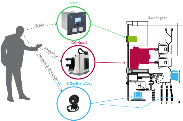
In power systems, electricity is generated, stepped up for transmission, stepped down at substations and finally distributed to end users. Without protection, a single fault — a short circuit or earth fault — can destroy equipment and cause widespread outages. The protection relay is the “brain” that prevents this: it detects the fault in milliseconds and sends a trip signal to the circuit breaker to clear it. The relay sits inside the medium-voltage switchgear panel, wired to the current and voltage transformers, and it is the component that turns a passive switchboard into a self-protecting system.
How medium voltage protection relays work
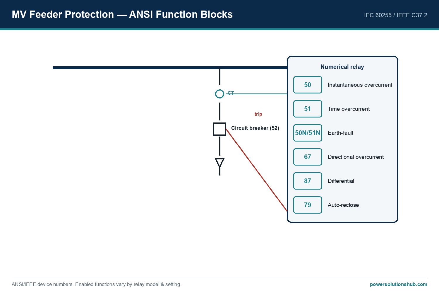
Modern MV relays are microprocessor-based (numerical) devices. They receive scaled signals from the current transformers (CTs) and voltage transformers (VTs), sample and analyse them in real time, and compare the measured quantities against pre-set protection settings. When a fault is detected — for example overcurrent, earth fault or undervoltage — the relay decides, based on its programmed logic and time curves, whether to trip the breaker.
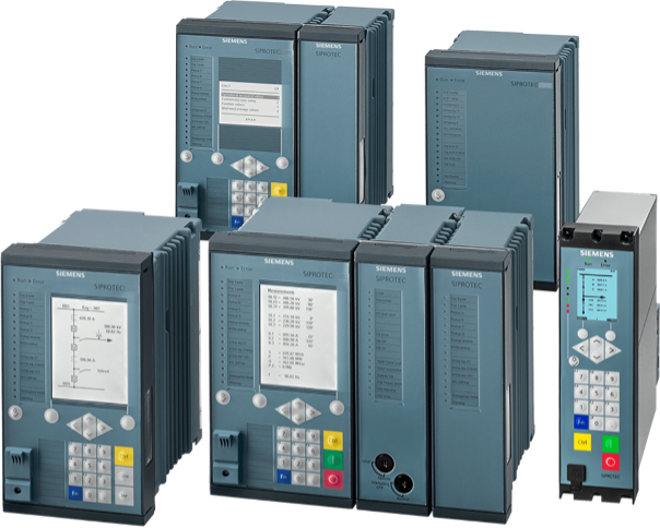
Beyond tripping, a modern relay also provides event and disturbance recording, metering, self-supervision and communication (IEC 61850, Modbus, DNP3) for remote monitoring and fault analysis. The ABB REF615, for example, is a dedicated feeder protection relay built on the IEC 61850 standard with transient/intermittent earth-fault protection and a transient disturbance recorder, while the Siemens SIPROTEC 5 platform supports IEC 61850 Edition 2 including 9-2 process-bus applications and integrated arc protection.
Relay technology: from electromechanical to numerical
Understanding the three generations helps when a network has mixed equipment:
- Electromechanical relays — the original technology, using discs and coils. Robust but limited to a single function each, with no communication.
- Static (solid-state) relays — analogue electronics; more functions, still limited.
- Numerical (digital) relays — today’s standard: one microprocessor device carries many protection functions, metering, recording and communication, and is configured entirely in software.
Almost all new MV installations use numerical relays, and the relay families below are all numerical platforms.
Protection functions and ANSI codes
Relay functions are standardised by ANSI/IEEE device numbers (IEEE C37.2) and characterised to IEC 60255. A relay is selected primarily by the protection functions it must provide. The most frequently used MV codes are:
| ANSI Code | Protection Function | Common Application |
|---|---|---|
| 27 | Undervoltage | Voltage protection |
| 50 | Instantaneous Overcurrent | Overcurrent protection |
| 51 | Time Overcurrent | Overcurrent protection |
| 50N / 51N | Instantaneous / Time Earth Fault | Earth-fault protection |
| 59 | Overvoltage | Voltage protection |
| 67 | Directional Overcurrent | Feeder protection |
| 67N | Directional Earth Fault | Directional earth-fault |
| 46 | Negative-Sequence (Unbalance) | Motor protection |
| 49 | Thermal Overload | Motor / transformer protection |
| 81 O/U | Over / Under Frequency | Frequency protection |
| 87T | Transformer Differential | Transformer protection |
| 87L | Line Differential | Line protection |
| 87G | Generator Differential | Generator protection |
| 21 | Distance | Distance protection |
| 50BF | Breaker Failure | Backup protection |
An engineer specifies a relay by listing the ANSI functions the application needs — for example a feeder relay typically needs 50/51 (overcurrent), 50N/51N (earth fault) and often 67 (directional), while a transformer relay adds 87T (differential) and 49 (thermal).
Types of medium voltage protection relays
Relays are grouped by application, each with a typical ANSI set:
- Feeder protection relay — for incoming and outgoing feeders; overcurrent (50/51), earth fault (50N/51N) and directional functions (67/67N). The ABB REF615 is a dedicated feeder relay.
- Transformer protection relay — differential (87T), overcurrent and thermal overload (49).
- Motor protection relay — overload (49), phase unbalance (46), locked-rotor and earth-fault protection.
- Generator protection relay — differential (87G), reverse power, and frequency protection.
- Busbar protection relay — fast differential protection of the busbar zone.
- Arc-flash protection relay — detects an internal arc optically and trips in milliseconds to limit damage and protect personnel.
Protection coordination and relay curves
Overcurrent protection is not just “trip when the current is too high” — it must be graded so that the relay closest to the fault trips first and the upstream relays act only as back-up. This selectivity is achieved with the inverse-time curves defined in IEC 60255: as the fault current rises, the tripping time falls, and the curve shape is chosen from standard inverse (SI), very inverse (VI), extremely inverse (EI) or definite-time characteristics. A downstream feeder relay is set on a faster curve (or lower time multiplier) than the upstream incomer, so a feeder fault is cleared by the feeder relay while the incomer holds back by a coordination margin (typically a few hundred milliseconds).
Directional overcurrent (67) adds another dimension: in a ring or parallel-fed network, the relay must know the direction of the fault current to trip only for faults in its own zone. Differential protection (87) works differently again — it compares the current entering and leaving a protected zone (a transformer, busbar or cable) and trips on any difference, giving fast, selective protection without a time delay. Getting these settings and their coordination right across the whole scheme is the core engineering task, and it depends directly on the network’s fault levels — see short circuit in power systems.
Relay families we supply
We supply and support the main global numerical relay platforms; each has its own in-depth guide:
- ABB — REF615 (dedicated feeder protection, IEC 61850) and the wider Relion family.
- Siemens — SIPROTEC 5 (modular platform) and SIPROTEC 4 (proven numerical technology).
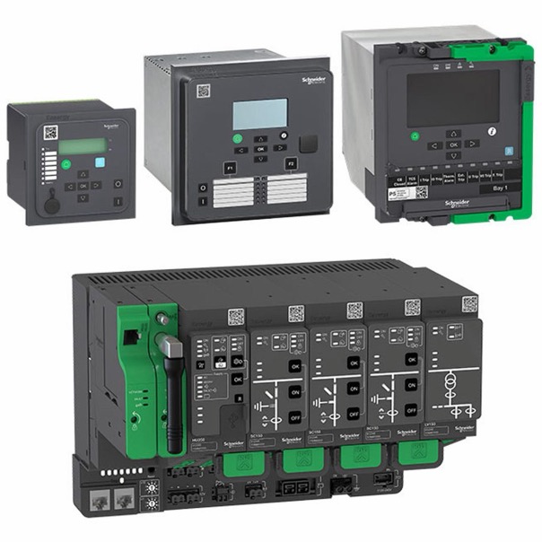
- Schneider Electric — Easergy (P1/P3/P5 series), Sepam (Sepam 20/S40), MiCOM, and the Schneider protection relay overview.
Each family offers different models with varying numbers of protection functions, communication options and I/O configurations; the linked guides give the model-level detail.
Choosing between relay families
With several strong numerical platforms available, the choice between families usually comes down to a few practical factors rather than raw protection capability, since all the leading platforms cover the standard ANSI functions:
- Existing installed base. Matching the relay family already used across a site simplifies spares, settings tools and operator training — a common reason to standardise on one platform.
- Communication and automation. If the substation is built around IEC 61850 with GOOSE interlocking or a process bus, choose a platform with mature IEC 61850 support (for example ABB REF615 or Siemens SIPROTEC 5).
- Application fit. A dedicated feeder relay (REF615) is efficient for a feeder; a modular platform (SIPROTEC 5) suits a substation needing many function combinations from one hardware family; Schneider Easergy, Sepam and MiCOM cover feeder, transformer and motor duties across their ranges.
- Configuration and lifecycle tools. The quality of the setting software, testing support and long-term firmware maintenance is often the deciding factor over a 15–20 year life.
Our role is to match the relay to the protection scheme, the communication architecture and the existing installed base — not simply to the datasheet.
Communication and IEC 61850
Modern MV relays are also communication nodes. IEC 61850 is the dominant substation-automation standard: it standardises how relays exchange data over Ethernet (GOOSE messaging for fast interlocking and protection signalling, MMS for SCADA), and its Edition 2 with 9-2 process bus digitises the CT/VT signals themselves. Relays such as the ABB REF615 (built on IEC 61850) and Siemens SIPROTEC 5 (IEC 61850 Edition 2, process bus) make substation-wide protection, control and monitoring interoperable across vendors. Modbus and DNP3 are also widely supported for legacy SCADA.
How to select and coordinate a relay
Selecting the right relay is only half the job; the settings and coordination are the other half.
- Required functions. List the ANSI functions the application needs (feeder, transformer, motor…) and choose a relay model that provides them.
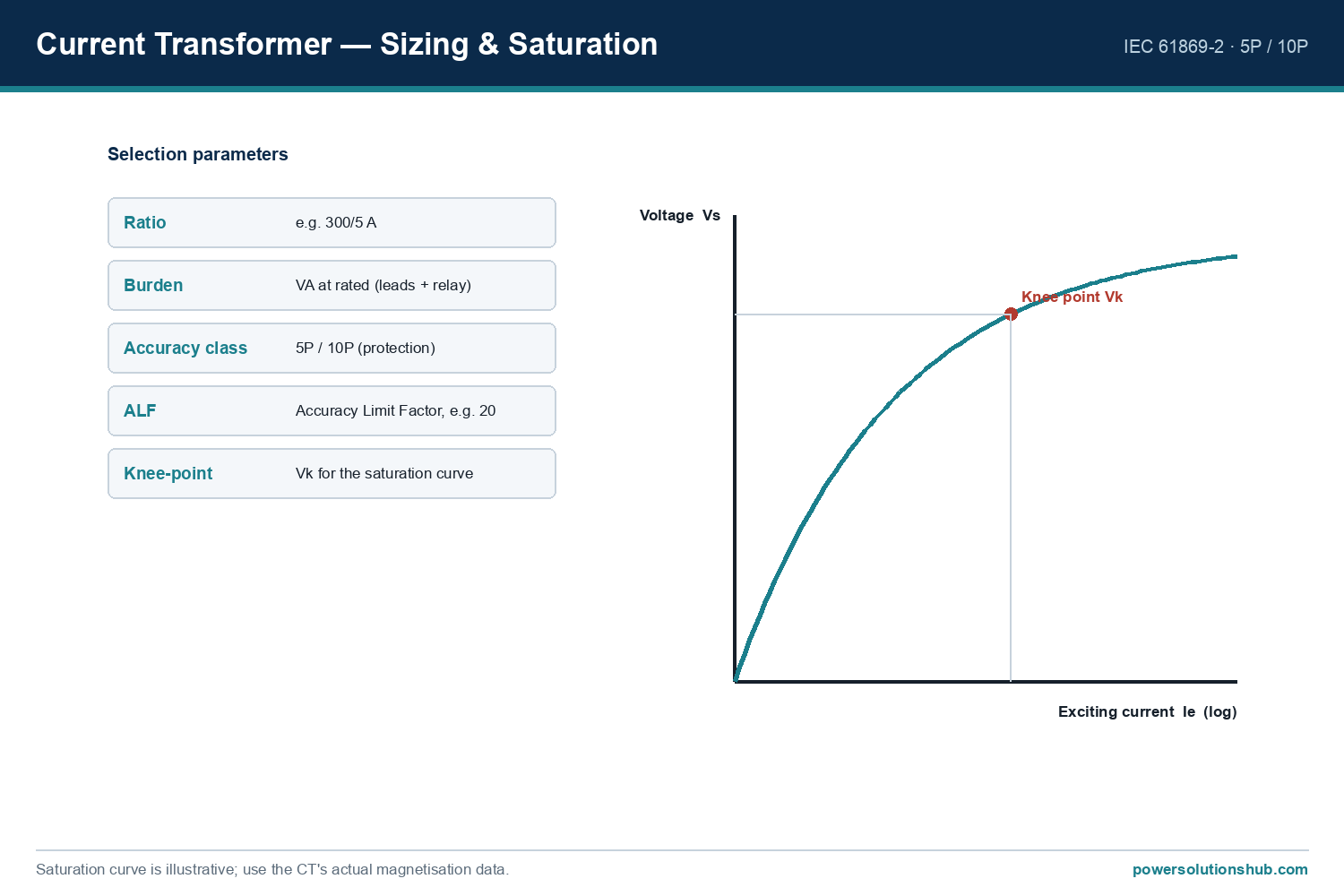
- CT/VT inputs. Confirm the relay’s rated current input (1 A / 5 A), voltage inputs and the number of analogue/digital I/O.
- Communication. Match the substation’s protocol (IEC 61850, Modbus, DNP3) and redundancy needs.
- Settings and selectivity. Calculate settings so the relay is selective (coordinated) with upstream and downstream devices — only the faulty section trips, the rest stays in service. This uses time grading, current grading and logic discrimination, with the overcurrent curves defined in IEC 60255 (standard inverse, very inverse, extremely inverse).
Even the best relay will mis-operate if its settings are wrong, so protection coordination is calculated for the whole scheme, not one relay in isolation. For the fault levels that drive these settings, see short circuit in power systems.
Testing, commissioning and the relay lifecycle
A protection relay only protects if it has been correctly set and proven. Before a relay is put into service it is commissioned by secondary injection: a test set injects simulated currents and voltages into the relay’s inputs and verifies that each protection function picks up at the right value and trips in the right time, and that the trip actually operates the circuit breaker. Numerical relays make this far easier than older technology, because the settings, the measured values and the event and disturbance records can all be read out digitally and archived.
Over the relay’s life, the same numerical platform supports self-supervision (the relay continuously checks its own health and raises an alarm on a fault), periodic testing, and firmware updates. When an older electromechanical or static scheme is modernised, a numerical relay retrofit typically replaces a whole panel of single-function relays with one multi-function device, adding IEC 61850 communication, metering and disturbance recording at the same time — a common upgrade path in ageing substations across the region. This lifecycle view matters when specifying: a relay is a 15–20 year asset whose communication and testing capabilities are as important as its raw protection functions.
Standards
MV protection relays are characterised and tested to the IEC 60255 series (measuring relays and protection equipment), their device functions are numbered to IEEE C37.2 (ANSI), and their communication follows IEC 61850 for substation automation. Relays installed in switchgear also operate within the switchgear’s IEC 62271 framework.
What is a medium voltage protection relay?
It is a numerical device that monitors an MV circuit’s current and voltage, detects faults such as short circuits and earth faults, and trips the circuit breaker to isolate the faulty section, protecting equipment and maintaining supply.
What are ANSI protection codes?
ANSI/IEEE device numbers (IEEE C37.2) identify each protection function — for example 50/51 overcurrent, 50N/51N earth fault, 67 directional overcurrent and 87 differential — and a relay is specified by the ANSI functions it provides.
What is the difference between a feeder, transformer and motor relay?
A feeder relay uses overcurrent, earth-fault and directional functions (50/51, 50N/51N, 67); a transformer relay adds differential (87T) and thermal (49); a motor relay adds unbalance (46) and locked-rotor protection.
Which protection relay brands do you supply?
We supply the main numerical platforms: ABB REF615/Relion, Siemens SIPROTEC 4 and 5, and Schneider Easergy, Sepam and MiCOM — each with its own detailed guide.
What is IEC 61850 and why does it matter?
IEC 61850 is the substation-automation standard that lets relays from different vendors exchange data over Ethernet (GOOSE, MMS) and, in Edition 2, digitise CT/VT signals over a process bus — enabling interoperable, substation-wide protection and control.
Why is relay selectivity (coordination) important?
Correct settings ensure only the faulty section is isolated while the rest of the network keeps running; this needs time grading, current grading and discrimination between upstream and downstream relays.
Looking for MV Protection Relays?
Looking for high-quality medium voltage protection relays — feeder, transformer, motor, differential or arc-flash protection from ABB, Siemens and Schneider? We provide expert engineering support and reliable products for all your medium voltage needs.
For quotations and requests: info@electricistanbul.com
WhatsApp: +90 501 076 69 91
[…] current as a proportionally scaled, safe secondary signal — typically 5 A or 1 A — for use by protection relays, meters, and measuring instruments. Correct CT sizing means selecting the right rated primary […]
[…] phase-to-phase, or phase-to-earth fault occurs, so that switchgear, cables, busbars, and protection relays can be correctly rated and coordinated. This guide walks through the governing method, a fully […]
[…] Electrical continuity is the whole point of a well-designed cabinet. Utility power (and, where present, a generator) feeds the ATS, which always selects the healthy source. From there the supply passes through the UPS, which rides through short interruptions on battery, and then to the PDU, which distributes conditioned power to every device. This is exactly the kind of resilient distribution and medium-voltage switchgear thinking used upstream in substations — only scaled down to a single cabinet. The same discipline of source selection, backup and protection applies whether the equipment is a rack ATS or a feeder protection relay. […]
[…] arc flash incidents, MV arcing faults can sustain very high currents for the full duration of the protection relay‘s clearing time, so the resulting incident energy at typical working distances can be severe. […]