
“`markdown
A medium-voltage (MV) switchgear cubicle is the metal-enclosed assembly that houses the circuit breaker or switch-disconnector, busbar, and protection interface used to connect, protect, and isolate a section of a distribution or industrial network between roughly 1 kV and 52 kV; correct cubicle selection means matching its rated voltage, rated current, and rated short-circuit withstand current to the actual network conditions at the point of installation. This guide walks through the first-principles calculations — not a specific manufacturer’s datasheet — that a specifying engineer uses to size a cubicle: the rated current formula, the short-circuit withstand check, internal arc classification, and the standards that govern the whole exercise. It is written for procurement and design teams working across the Middle East and Gulf region (including Egypt and Saudi Arabia), North Africa, CIS countries, and Sub-Saharan Africa, where MV networks span a wide mix of voltage levels and fault levels depending on utility and industrial practice.
Selecting the wrong cubicle rating is one of the most common — and most expensive — mistakes in MV project engineering. Undersizing the short-circuit withstand current risks catastrophic failure and safety hazard during a fault; oversizing wastes capital and increases footprint unnecessarily. Because switchgear is procured years before commissioning and is expensive to retrofit, the selection method needs to be systematic, documented, and repeatable — which is exactly what a load-flow and fault-level based sizing exercise provides.
The method: three ratings you must calculate
Every MV cubicle selection reduces to checking three parameters against the network:
1. Rated voltage (Ur). The cubicle’s rated voltage and insulation level must be equal to or greater than the system’s nominal voltage and its expected transient/lightning overvoltages. This is a straightforward “system kV ≤ cubicle rated kV” match and is normally fixed by the utility or plant voltage class.
2. Rated normal current (Ir). The cubicle busbar and breaker must carry the maximum continuous load current, including planned growth margin, without exceeding thermal limits. This is derived from the connected load using:
I = S / (√3 × V)
where S is the apparent power in kVA, V is the line-to-line voltage in kV, and I is the resulting current in amperes. For a feeder cubicle, S is the sum of downstream transformer or load ratings on that circuit; for an incomer, it is the total substation demand.
3. Rated short-circuit breaking/withstand current (Isc). The cubicle, breaker, and busbar must survive and interrupt the maximum prospective fault current at that point in the network for the specified duration (commonly expressed as a 1-second or 3-second thermal withstand rating). This is obtained from a fault-level study using:
Isc = V / (√3 × Zsource)
where Zsource is the total impedance (source + transformer + cable) back to the infinite bus, expressed in ohms referred to the voltage of the switchgear location. In practice this value comes from a short-circuit study (often software-based) rather than hand calculation once the network has more than one or two impedance elements, but the underlying relationship is the same Ohm’s-law expression.
Both Ir and Isc must be checked at every point the cubicle sits in the network — a busbar rating at the incomer is not automatically the same requirement as at an outgoing feeder.
Worked example: sizing a feeder cubicle
Assume a distribution substation with an 11 kV busbar feeding a 1000 kVA distribution transformer through a dedicated feeder cubicle, and the utility has confirmed a maximum three-phase fault level of 350 MVA at the 11 kV busbar.
Step 1 — Rated normal current of the feeder:
For example, with S = 1000 kVA and V = 11 kV:
I = S / (√3 × V) = 1000 / (1.732 × 11) ≈ 52.5 A
Adding a design margin for future load growth (a common practice is +25–50%), the feeder cubicle should be specified with a rated current comfortably above this figure — for instance, selecting from a standard commercial rating step such as 630 A or 1250 A rather than sizing exactly to 52.5 A, since switchgear ratings are supplied in discrete steps, not custom values.
Step 2 — Rated short-circuit withstand current at the busbar:
For example, converting the confirmed fault level of 350 MVA at 11 kV into a fault current:
Isc = S_fault / (√3 × V) = 350,000 / (1.732 × 11) ≈ 18,370 A ≈ 18.4 kA
The busbar and every cubicle connected to it — incomer, bus-coupler, and all feeders — must therefore have a rated short-circuit breaking/withstand current equal to or greater than approximately 18.4 kA for the duration specified in the fault study (typically 1 s or 3 s). This is the single most safety-critical number in the selection process, because it must hold for the whole busbar, not just the feeder under review.
Step 3 — Cross-check against standard rating steps:
Since manufacturers offer switchgear in discrete standard current and short-circuit rating steps rather than the exact calculated value, the specifying engineer rounds up to the next available combination of rated current and rated short-circuit current that meets or exceeds both Step 1 and Step 2 results, then confirms voltage class compatibility with the system’s 11 kV nominal level.
Selection and comparison table
| Parameter | Formula / basis | Example result | Selection rule |
|---|---|---|---|
| Rated voltage (Ur) | System nominal + insulation margin | 11 kV system | Ur ≥ system nominal voltage |
| Rated normal current (Ir) | I = S/(√3×V) | ≈52.5 A (1000 kVA @ 11 kV) | Ir ≥ calculated load current + growth margin |
| Rated short-circuit current (Isc) | Isc = Sfault/(√3×V) | ≈18.4 kA (350 MVA @ 11 kV) | Isc ≥ prospective fault current at that busbar |
| Withstand duration | From protection/fault study | 1 s or 3 s (per study) | Match cubicle thermal withstand time to relay clearance time |
| Internal arc classification (IAC) | Per IEC 62271-200 test type | Type A or B, accessibility class | Select per personnel accessibility and installation layout |
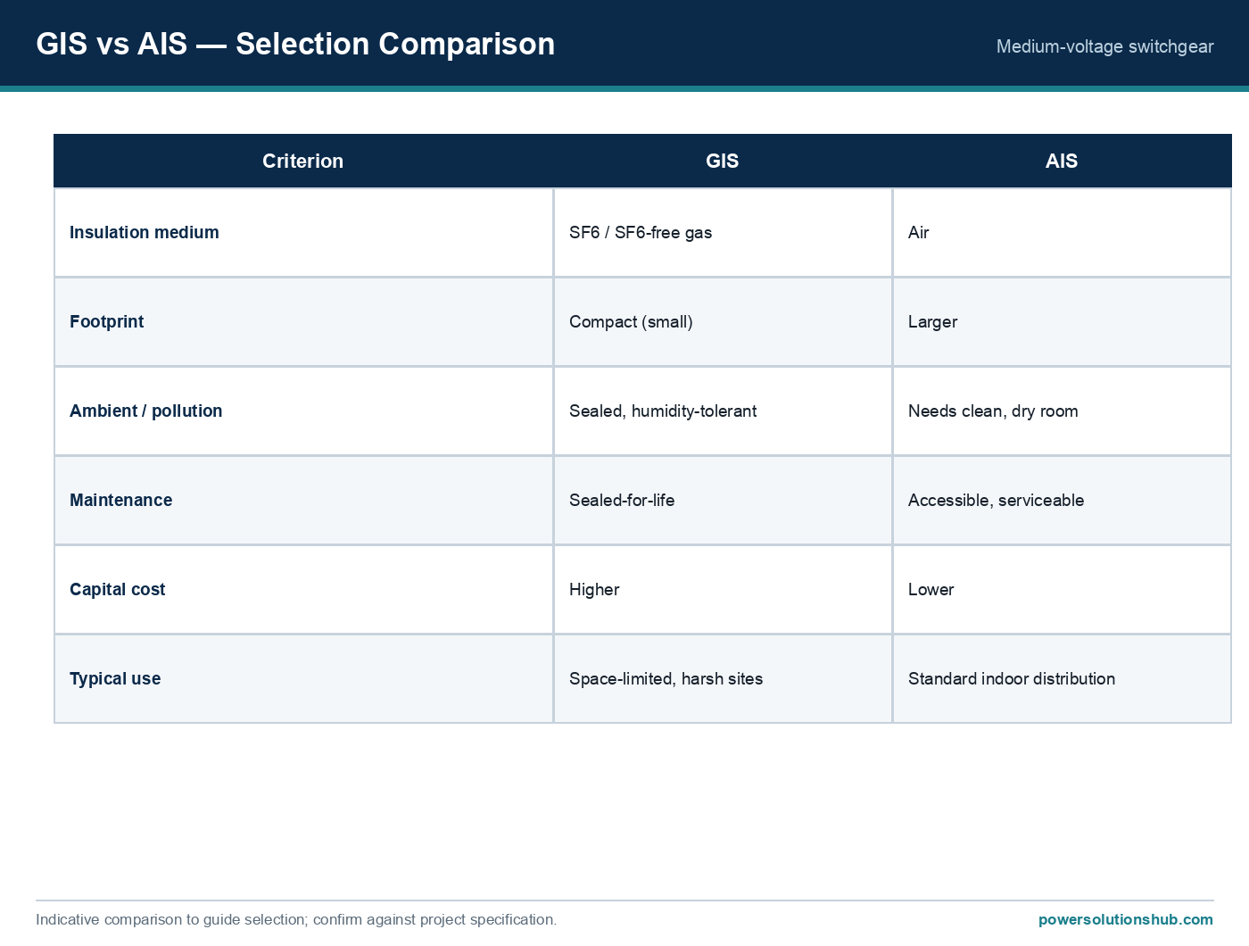
| Enclosure/insulation medium | Air-insulated or gas-insulated | Site-dependent | Match to climate, maintenance policy, footprint constraints |
Selection criteria and common pitfalls
Beyond the two headline calculations, a complete cubicle selection should also address:
- Busbar continuity across the section. All cubicles on a common busbar section must share the same short-circuit withstand rating — mixing ratings on one bus creates a weak link that defeats the higher-rated equipment.
- Withdrawable vs fixed-mounted breakers. Withdrawable designs simplify maintenance and testing by allowing the breaker to be racked out without de-energizing the whole busbar, an important operational criterion in facilities requiring high availability.
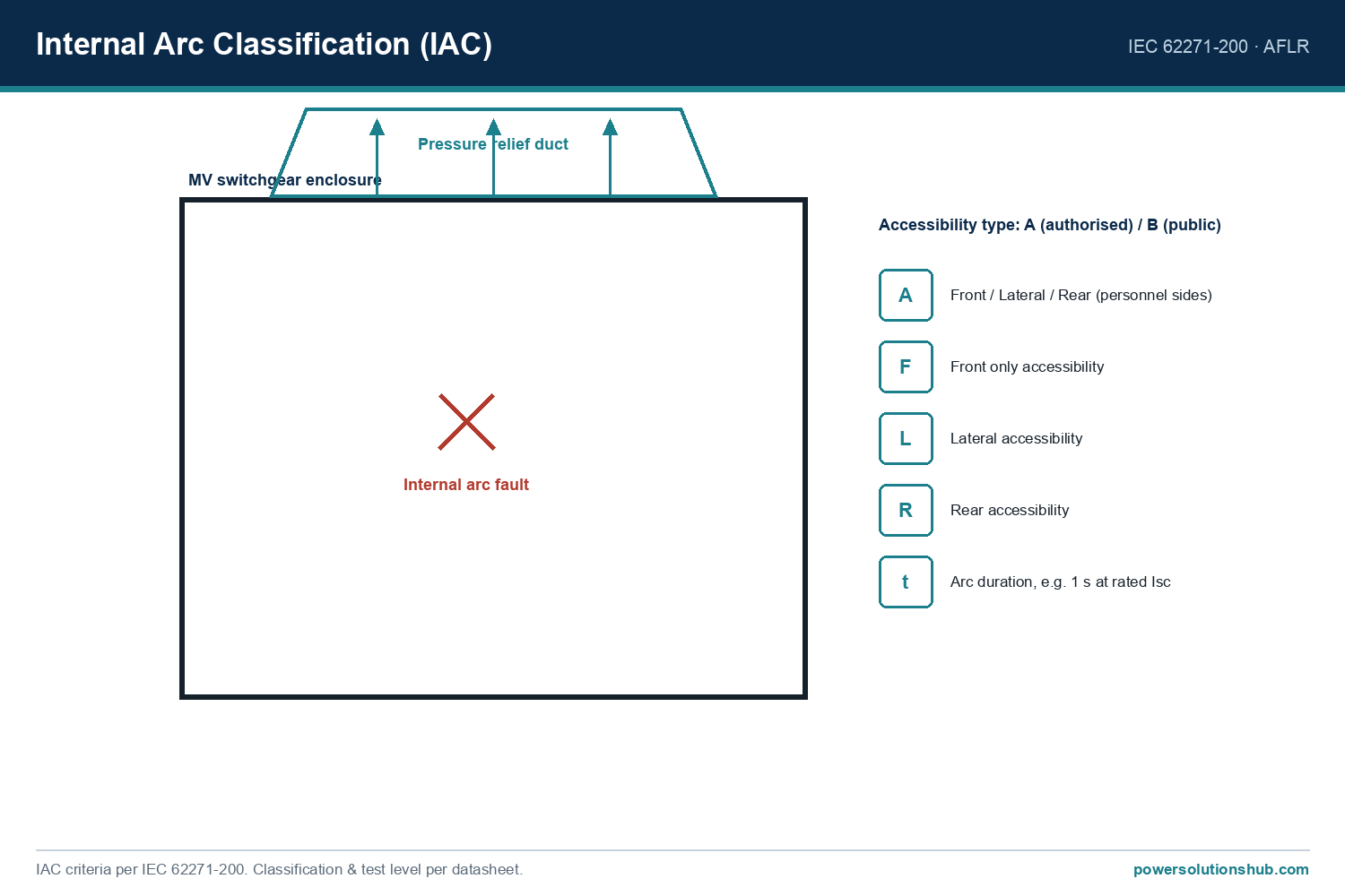
- Internal arc classification (IAC). IEC 62271-200 defines type-tested internal arc classification (commonly referenced as IAC A or IAC B, with accessibility categories) confirming that, in the event of an internal fault, the enclosure directs arc energy away from the operator side rather than through access panels. This should be selected based on where personnel stand relative to the switchgear during normal operation.
- Growth margin vs over-specification. Sizing purely to the present-day calculated current leaves no headroom for load growth; sizing far beyond the fault-level study wastes capital. The standard-rating-step approach in the worked example above balances both.
- Protection coordination. The cubicle’s breaker interrupting rating must be coordinated with the protection relay‘s fault-clearing time — see our protection relay guide for how relay settings and breaker withstand time interact during a fault.
- Transformer feeder sizing. Where a cubicle feeds a transformer directly, the feeder current calculation should use the transformer’s rated primary current, not just its nameplate kVA in isolation — our transformer sizing resources cover this calculation in more depth.
- Altitude, temperature, and pollution derating. Ambient conditions above standard reference values can derate a cubicle’s current-carrying capacity; this is a frequent oversight in high-altitude or high-ambient-temperature GEO region installations.
For the switchgear family itself — air-insulated, gas-insulated, and ring main unit options — see our main switchgear hub page, which explains how enclosure type and busbar arrangement interact with the ratings calculated here.
Standards
The rated voltage, rated current, rated short-circuit current, and internal arc classification testing described above are defined under IEC 62271-1 (common specifications for high-voltage switchgear and controlgear) and IEC 62271-200 (AC metal-enclosed switchgear and controlgear for rated voltages above 1 kV and up to and including 52 kV, including internal arc classification). Protection coordination and relay-side fault clearing typically follow IEC 60255 for protection relay standards. Where equipment is specified for regions using IEEE-based practices, IEEE C37 series standards for switchgear apply an analogous rating philosophy.
Related guides
See also our guides on gas-insulated switchgear, metal-clad switchgear and air-insulated switchgear.
What is the difference between rated current and rated short-circuit current in switchgear selection?
Rated current (Ir) is the continuous current the cubicle carries under normal load without overheating, calculated from connected kVA and system voltage. Rated short-circuit current (Isc) is the maximum fault current the cubicle must safely withstand and/or interrupt for a defined duration during a fault — a much larger, short-duration figure derived from a fault-level study rather than load data.
How do I calculate the rated current for a transformer feeder cubicle?
Use I = S/(√3×V), where S is the transformer’s rated apparent power in kVA and V is the system line-to-line voltage in kV. Add a growth margin, then select the next available standard current rating step.
Why must every cubicle on the same busbar have the same short-circuit rating?
Because a fault anywhere on the busbar exposes every connected cubicle to the same prospective fault current. If one cubicle has a lower short-circuit withstand rating than the busbar’s actual fault level, it becomes the weakest point and can fail catastrophically even though neighboring cubicles are correctly rated.
What is internal arc classification (IAC) and why does it matter for selection?
IAC, defined under IEC 62271-200, is a type-tested classification confirming how a switchgear enclosure directs arc energy and pressure in the event of an internal fault, protecting personnel standing at accessible sides. Selection should consider IAC class relative to where operators are positioned during normal switching operations.
Should I size switchgear only for today’s load, or include growth margin?
Sizing only to today’s calculated load current leaves no room for future expansion and can force an early switchgear replacement. A common practice is to include a growth margin above the calculated current before rounding up to the nearest standard rating step, balancing capital cost against future flexibility.
Does ambient temperature or altitude affect switchgear current rating?
Yes — current-carrying capacity is typically referenced to standard ambient conditions, and higher ambient temperature or altitude can derate the cubicle’s effective continuous current rating, which matters for installations in hot-climate GEO region sites.
Which IEC standard governs MV switchgear rating and testing?
IEC 62271-1 provides the common specifications for high-voltage switchgear and controlgear, while IEC 62271-200 specifically covers AC metal-enclosed switchgear for voltages up to and including 52 kV, including internal arc classification testing. “`
Looking for medium voltage switchgear?
Looking for high-quality medium voltage switchgear? We provide expert engineering support and reliable products for all your medium voltage needs.
For quotations and requests: info@electricistanbul.com
WhatsApp: +90 501 076 69 91