
Short-circuit current calculation is the engineering process of determining the magnitude of fault current — initial symmetrical (Ik″), peak (ip), and thermal equivalent (Ith) — that flows in a medium-voltage network when a three-phase, phase-to-phase, or phase-to-earth fault occurs, so that switchgear, cables, busbars, and protection relays can be correctly rated and coordinated. This guide walks through the governing method, a fully worked numerical example from grid to busbar, a comparison table for equipment selection, common pitfalls, and the applicable IEC/IEEE standards. The approach applies equally to utility substations and industrial MV switchrooms across the Middle East and Gulf region (including Egypt and Saudi Arabia), North Africa, the CIS, and Sub-Saharan Africa, where grid strength and transformer sizing vary widely from site to site.
Why short-circuit calculation matters
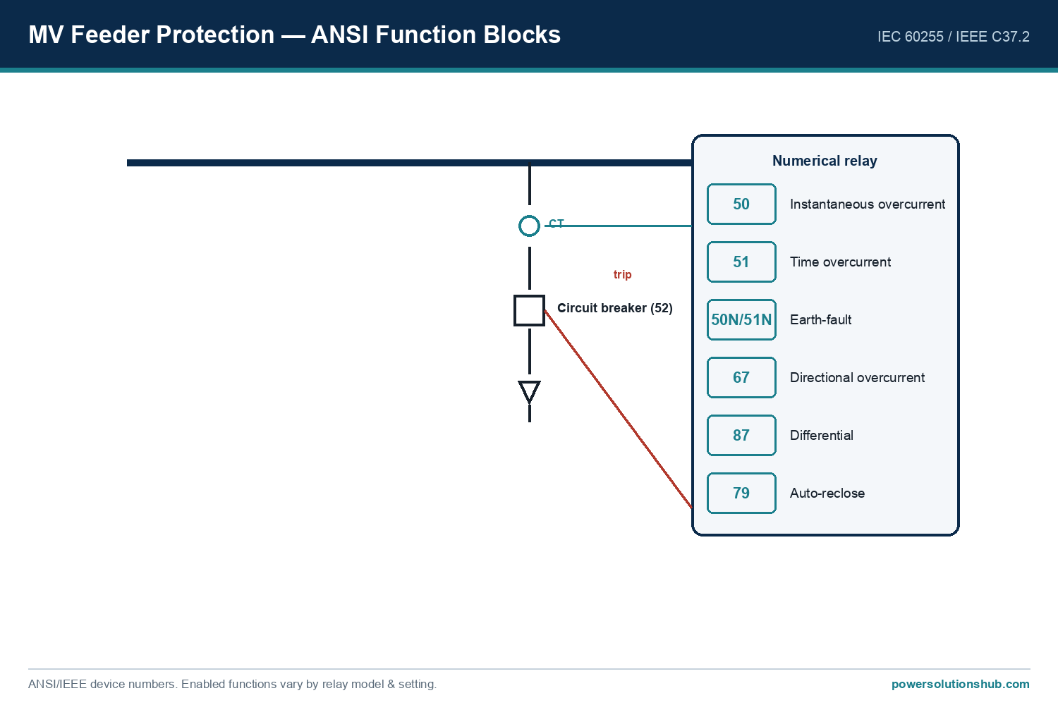
Every piece of MV equipment — switchgear, [medium voltage switchgear](https://powersolutionshub.com/what-is-mv-switchgear-medium-voltage-switchgear/) busbars, cable sizing, current transformers, and medium voltage protection relays — is only safe and selective if it is rated above the maximum fault current the network can actually deliver at that point. Undersizing leads to catastrophic failure (arcing faults, busbar burn-through); oversizing wastes capital. The calculation also feeds directly into protection relay settings: instantaneous and time-delayed overcurrent thresholds are set as a function of Ik″ at each protection zone, and correct discrimination between upstream and downstream relays depends on knowing how fault current changes along the network.
The method / formula (IEC 60909 approach)
The internationally recognised method for calculating three-phase short-circuit currents is defined in IEC 60909-0, “Short-circuit currents in three-phase AC systems — Calculation of currents.” The IEEE equivalent guidance is found in IEEE Std 551 (the “Violet Book”) and ANSI/IEEE C37.010, used mainly in North American practice for symmetrical-current-rated breakers.
The core steps are:
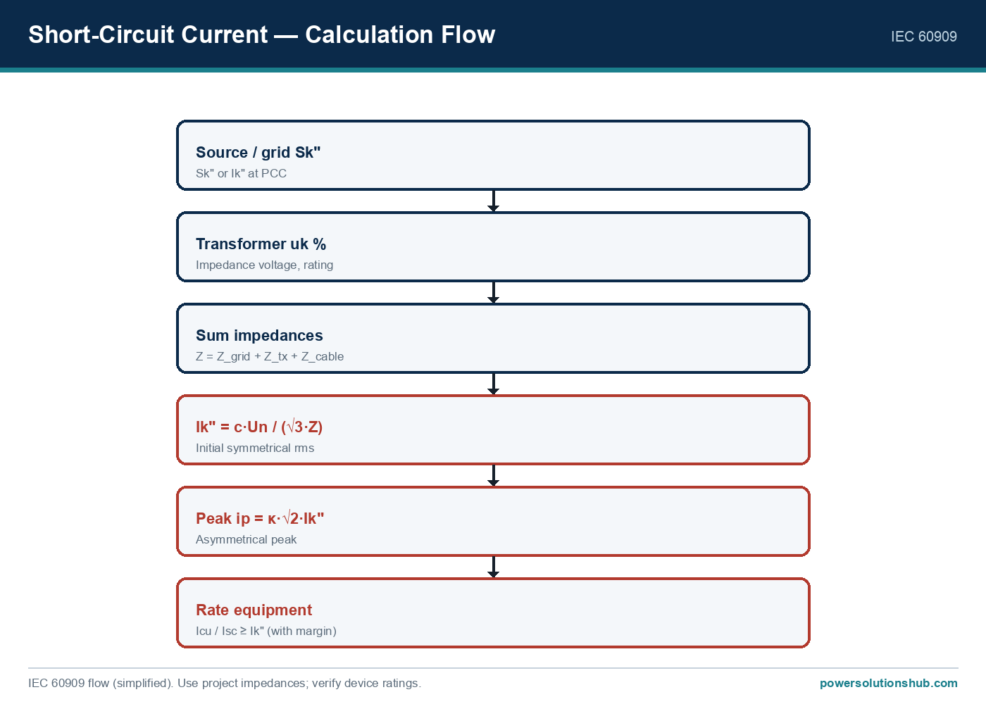
1. Rated (load) current — establishes normal operating current, used as a sanity check: I = S / (√3 × Un)
2. Source/grid impedance, derived from the known short-circuit power (Sk″) at the point of connection: Zs = c × Un² / Sk″
3. Transformer impedance, from its rated impedance voltage (uk%): Zt = (uk% / 100) × (Un² / Sn)
4. Total impedance to the fault point: Ztotal = ΣZ (source + transformer + cable/line impedances, added as complex R+jX)
5. Initial symmetrical short-circuit current: Ik″ = c × Un / (√3 × Ztotal)
6. Peak short-circuit current (accounts for the DC offset in the first half-cycle): ip = κ × √2 × Ik″
7. Thermal equivalent short-time current (Ith), used to check thermal withstand of cables and busbars over the protection clearance time.
The factor c is the IEC 60909 voltage factor (typically 1.1 for maximum-current calculations in MV networks, and a lower value for minimum-current studies used in relay sensitivity checks). The factor κ depends on the network’s X/R ratio and is read from IEC 60909 curves or approximated for hand calculations.
Worked example
Assume the following simplified radial network, from utility connection down to an 11 kV industrial switchboard:
- Utility grid short-circuit power at the 33 kV point of connection: Sk″ = 500 MVA
- Step-down transformer: 33/11 kV, 10 MVA, impedance voltage uk = 8%
- Voltage factor per IEC 60909: c = 1.1
- Assume reactance dominates (X ≈ Z) for a first-pass hand calculation — a simplification acceptable for MV networks with high X/R ratios; a full study should keep R and X separate.
Step 1 — Source impedance, referred to the 11 kV side: Zs = c × Un² / Sk″ = 1.1 × (11,000 V)² / 500,000,000 VA Zs = 1.1 × 121,000,000 / 500,000,000 ≈ 0.266 Ω
Step 2 — Transformer impedance, referred to the 11 kV secondary: Zt = (uk / 100) × (Un² / Sn) = 0.08 × (121,000,000 / 10,000,000) Zt = 0.08 × 12.1 ≈ 0.968 Ω
Step 3 — Total impedance to the 11 kV busbar: Ztotal = Zs + Zt = 0.266 + 0.968 ≈ 1.234 Ω
Step 4 — Initial symmetrical short-circuit current at the 11 kV busbar: Ik″ = c × Un / (√3 × Ztotal) = (1.1 × 11,000) / (1.732 × 1.234) Ik″ = 12,100 / 2.137 ≈ 5,662 A ≈ 5.66 kA
Step 5 — Peak short-circuit current (assume κ = 1.8, a typical value for a transformer-dominated MV feeder with moderate X/R): ip = κ × √2 × Ik″ = 1.8 × 1.414 × 5,662 ≈ 14,410 A ≈ 14.4 kA
Step 6 — Thermal equivalent short-time current (simplified, ignoring DC decay factors m and n, over a 1-second protection clearance time): Ith ≈ Ik″ ≈ 5.66 kA for 1 s
This tells the design engineer that the 11 kV switchboard, its busbars, and the incoming feeder cable must be rated for an initial symmetrical fault current of at least ~5.7 kA, a peak (making) current of at least ~14.4 kA, and a 1-second thermal withstand of at least ~5.7 kA. The result also becomes the basis for setting the instantaneous pickup of the incoming medium voltage protection relay, which should be set below the calculated Ik″ with margin, but above maximum load and inrush currents.
Fault-level progression and equipment selection table
| Network point | Impedance to point (Ω) | Ik″ (initial symmetrical) | Peak ip (κ=1.8) | Relevance |
|---|---|---|---|---|
| 33 kV grid connection | Zs ≈ 0.266 (ref. 11 kV) | ~24.9 kA (at 33 kV side, illustrative) | — | Utility infeed strength |
| 11 kV transformer secondary / MV busbar | Ztotal ≈ 1.234 | ≈ 5.66 kA | ≈ 14.4 kA | Governs switchgear breaking/making rating |
| Downstream 11 kV feeder (after cable impedance added) | Ztotal + Zcable (higher) | Lower than 5.66 kA | Lower than 14.4 kA | Governs feeder relay grading and cable thermal check |
The table illustrates the general first-principles rule: fault current is highest closest to the source and decreases as impedance (transformer + cable) is added downstream. This progression is exactly what protection engineers use to grade relay time-current curves for selectivity.
Selection criteria and common pitfalls
When using the calculated Ik″, ip, and Ith to select or verify equipment, check the following:
- Rated short-circuit breaking current of the switchgear must be ≥ calculated Ik″ at that busbar, with margin for future network growth.
- Rated peak withstand (making) current must be ≥ calculated ip — this is the mechanical stress the switchgear and busbar must survive during the first cycle.
- Rated short-time withstand current and duration must cover the calculated Ith for the actual protection clearance time (commonly 1 s or 3 s in specifications), not just the instantaneous value.
- Motor contribution: rotating machines (motors, generators) connected to the busbar add their own fault-current contribution during the first cycles and must be included in industrial plant calculations — omitting it is a frequent source of under-rated switchgear.
- X/R ratio accuracy: using a generic κ value without checking the actual X/R ratio of the network can under- or over-estimate the peak current significantly; transformer-dominated MV networks typically have higher X/R (higher κ) than cable-dominated LV networks.
- Minimum vs maximum fault current: use c-factor for maximum current (breaker sizing) and the corresponding lower c-factor for minimum current studies (relay sensitivity and reach checks) — using only the maximum case can leave remote-end faults undetected by protection.
- Meshed vs radial topology: parallel transformers or ring-fed networks require impedance combination (parallel Z) rather than simple series addition, and often need computer-based short-circuit software rather than hand calculation.
- Data source impedance: an inaccurate utility Sk″ figure (often just an assumption at design stage) is one of the most common root causes of later fault-level disputes — always confirm with the utility before finalising switchgear and transformer impedance selection.
Standards
The primary reference for MV three-phase short-circuit calculations is IEC 60909-0, “Short-circuit currents in three-phase AC systems — Calculation of currents,” which defines the voltage factor c, the peak factor κ, and the thermal equivalent current methodology used throughout this guide. In IEEE-based practice, IEEE Std 551 (Violet Book) and ANSI/IEEE C37.010 provide the equivalent framework for symmetrical- and asymmetrical-current-rated circuit breakers. Protection relay coordination studies built on these fault levels typically reference IEC 60255 for relay performance and IEC 61850 where digital substation communication is involved.
Related guides
See also our guides on gas-insulated switchgear, ring main units and metal-clad switchgear.
What is the difference between Ik″, ip, and Ith?
Ik″ is the initial symmetrical RMS short-circuit current at the instant of fault, ip is the peak (asymmetrical) current reached within the first half-cycle including the DC offset, and Ith is the thermal equivalent RMS current used to check the withstand capability of cables, busbars, and switchgear over the fault clearance time.
Why does the voltage factor c matter?
The IEC 60909 factor c accounts for voltage variations, transformer tap positions, and subtransient behaviour of sources; using c=1.1 for maximum-current studies ensures switchgear is rated for the worst realistic fault current, while a lower c is used for minimum-current relay sensitivity checks.
Do I need to include motor contribution in every MV short-circuit study?
Yes, in industrial plants with significant motor load. Induction and synchronous motors feed additional fault current into a nearby short circuit for the first several cycles, and this contribution can materially increase both Ik″ and ip at the switchboard.
How does short-circuit current calculation affect protection relay settings?
The calculated Ik″ at each protection zone defines the range within which instantaneous and time-delayed overcurrent elements of the [protection relay](/medium-voltage-protection-relays) must be set — high enough to avoid nuisance tripping on load/inrush, but low enough to guarantee fast clearance of an actual fault, while maintaining discrimination with adjacent relays.
Can I use a simplified reactance-only calculation instead of full R+jX?
For quick hand calculations on transformer-dominated MV networks with high X/R ratios, a reactance-only approximation is common and reasonably accurate; however, for cable-dominated or low-voltage-adjacent networks, resistance becomes significant and should not be ignored in a detailed study.
What happens if switchgear is under-rated for the calculated fault current?
Equipment rated below the actual Ik″/ip/Ith at its installation point risks catastrophic failure during a real fault — including internal arcing, busbar deformation, or explosive rupture — which is why fault-level verification is mandatory before finalising [switchgear](/medium-voltage-switchgear) and cable specifications on any project.
How does adding a second parallel transformer change the calculation?
Parallel transformers reduce the total source impedance seen at the shared busbar (impedances combine as parallel elements), which increases the fault current at that busbar compared with a single-transformer feed — this is a common reason fault levels rise after plant expansions and require re-verification of existing switchgear.
Looking for medium voltage protection relays?
Looking for high-quality medium voltage protection relays? We provide expert engineering support and reliable products for all your medium voltage needs.
For quotations and requests: info@electricistanbul.com
WhatsApp: +90 501 076 69 91