
“`
Protection relay coordination (also called selectivity or discrimination) is the engineering practice of setting the pickup current and time delay of series-connected protection relays so that only the relay closest to a fault operates first, isolating the smallest possible section of the network while all upstream relays remain in standby as backup. Achieving correct coordination requires a disciplined method: define fault currents at each network point, choose relay curve characteristics, calculate pickup and time settings, and verify the grading margin between adjacent devices on a time-current curve. This guide walks through the underlying formulas, a fully worked grading example between a transformer and an outgoing feeder relay, a practical settings-comparison table, common selection criteria, and the governing IEC/IEEE standards, with relevance for utilities and industrial operators across the Middle East and Gulf region including Egypt and Saudi Arabia, North Africa, the CIS, and Sub-Saharan Africa, where growing MV networks demand reliable fault discrimination.
Correct coordination matters because a badly graded protection scheme either trips too many breakers for a single fault (loss of selectivity, wide-area blackout) or trips too slowly (excessive equipment stress, arc-flash energy, and reduced personnel safety). Since protection relays at different voltage levels and feeder positions all “see” the same fault current with different magnitudes, coordination is fundamentally a mathematical exercise in comparing operating times along a common time-current curve, not a matter of trial and error in the field. Getting the calculations right at the design stage avoids costly re-commissioning and nuisance outages once the switchgear is energized.
The method: time-current curves, pickup, and grading margin
Protection relay coordination rests on three linked calculations.
1. Pickup current (relay setting current). The relay’s minimum operating current, Is, is normally set as a multiple of the protected element’s rated current In:
Is = k × In
where k (often called the plug setting multiplier) is chosen above maximum expected load and below the minimum fault current the relay must detect, so that the relay does not trip on load or inrush but reliably picks up on internal faults.
2. Time-current characteristic. Most overcurrent relays (electromechanical or numerical, IDMT type) follow the standard inverse-time formula defined in IEC 60255-151:
t = TMS × [ k / ( (I/Is)^α − 1 ) ]
where: – t = operating time – TMS (or TDS in IEEE terminology) = time multiplier setting / time dial setting – I = fault current seen by the relay – Is = pickup current – k and α = constants that define the curve shape (standard inverse, very inverse, extremely inverse)
3. Grading margin (discrimination time). Between two relays in series — an upstream (backup) relay and a downstream (primary) relay — the operating time difference must exceed a minimum margin Δt to allow for breaker interrupting time, relay overshoot, and CT/measurement errors:
t_upstream − t_downstream ≥ Δt
A typical engineering margin used in grading studies is in the range of 0.3–0.5 seconds, covering breaker trip time, relay reset/overshoot, and a safety allowance — the exact value is a design choice validated against the specific relay and breaker combination, not a fixed universal constant.
Worked example: grading a transformer relay against a feeder relay
Consider a simple radial system: a medium-voltage feeder relay (Relay F) protects an outgoing cable, and an upstream transformer relay (Relay T) protects the transformer feeding that busbar. Assume a 3-phase fault occurs just downstream of the feeder breaker, and the fault current measured by both relays (in a simple radial topology, both relays see essentially the same fault current) is I = 2000 A.
Step 1 — Determine rated currents and pickup settings. Suppose the feeder cable is rated so that its relay pickup is set at Is_F = 400 A, and the transformer relay pickup, based on the transformer’s rated current, is set at Is_T = 500 A.
Step 2 — Compute the current multiple of setting for each relay. For Relay F: I/Is_F = 2000/400 = 5.0 For Relay T: I/Is_T = 2000/500 = 4.0
Step 3 — Apply the standard inverse-time formula. Using the IEC standard inverse curve constants k = 0.14 and α = 0.02:
t = TMS × [0.14 / ((I/Is)^0.02 − 1)]
For Relay F with TMS = 0.10: (5.0)^0.02 = e^(0.02 × ln5) = e^(0.02 × 1.609) = e^0.0322 ≈ 1.0327 t_F = 0.10 × [0.14 / (1.0327 − 1)] = 0.10 × [0.14 / 0.0327] = 0.10 × 4.28 ≈ 0.428 s
Step 4 — Determine the TMS required for Relay T to grade above Relay F by the chosen margin. Target: t_T ≥ t_F + Δt = 0.428 + 0.4 = 0.828 s (using a 0.4 s grading margin for this example).
For Relay T: (4.0)^0.02 = e^(0.02 × ln4) = e^(0.02 × 1.386) = e^0.0277 ≈ 1.0281 t_T = TMS_T × [0.14 / (1.0281 − 1)] = TMS_T × [0.14 / 0.0281] = TMS_T × 4.98
Solving for TMS_T: TMS_T = 0.828 / 4.98 ≈ 0.166
So the transformer relay (Relay T) should be set with TMS ≈ 0.17 to clear the same fault in roughly 0.83 seconds, about 0.4 seconds after the feeder relay operates at 0.428 seconds — giving Relay F the first opportunity to isolate the fault and leaving Relay T as a time-graded backup. This is the essence of a coordination (grading) study: repeat Steps 1–4 for every fault location and every relay pair in the network, from the smallest downstream feeder outward to the highest upstream backup relay.
Settings comparison and coordination checklist
| Parameter | Relay F (feeder, downstream) | Relay T (transformer, upstream) |
|---|---|---|
| Pickup current Is | 400 A | 500 A |
| Fault current seen | 2000 A | 2000 A |
| Multiple of setting (I/Is) | 5.0 | 4.0 |
| Curve type | IEC standard inverse (k=0.14, α=0.02) | IEC standard inverse (k=0.14, α=0.02) |
| TMS / TDS | 0.10 | ≈0.17 |
| Computed operating time | ≈0.428 s | ≈0.83 s |
| Grading margin achieved | — | ≈0.40 s |
Note: all current, TMS, and time values above are illustrative computed figures for this worked example, not manufacturer-specific product ratings.
Selection criteria and common pitfalls
When performing a coordination study, engineers should evaluate:
- Curve family selection. Standard inverse, very inverse, and extremely inverse curves each suit different fault-current profiles; extremely inverse curves are often preferred where fault current changes little with distance (e.g., near transformers), because they separate operating times more effectively at close-in faults.
- Instantaneous elements. Many schemes add a high-set instantaneous stage above the maximum through-fault current to speed up clearance for close-in faults without compromising downstream selectivity — the instantaneous pickup must be set above the maximum fault current seen at the remote end of the protected zone to avoid mis-coordination.
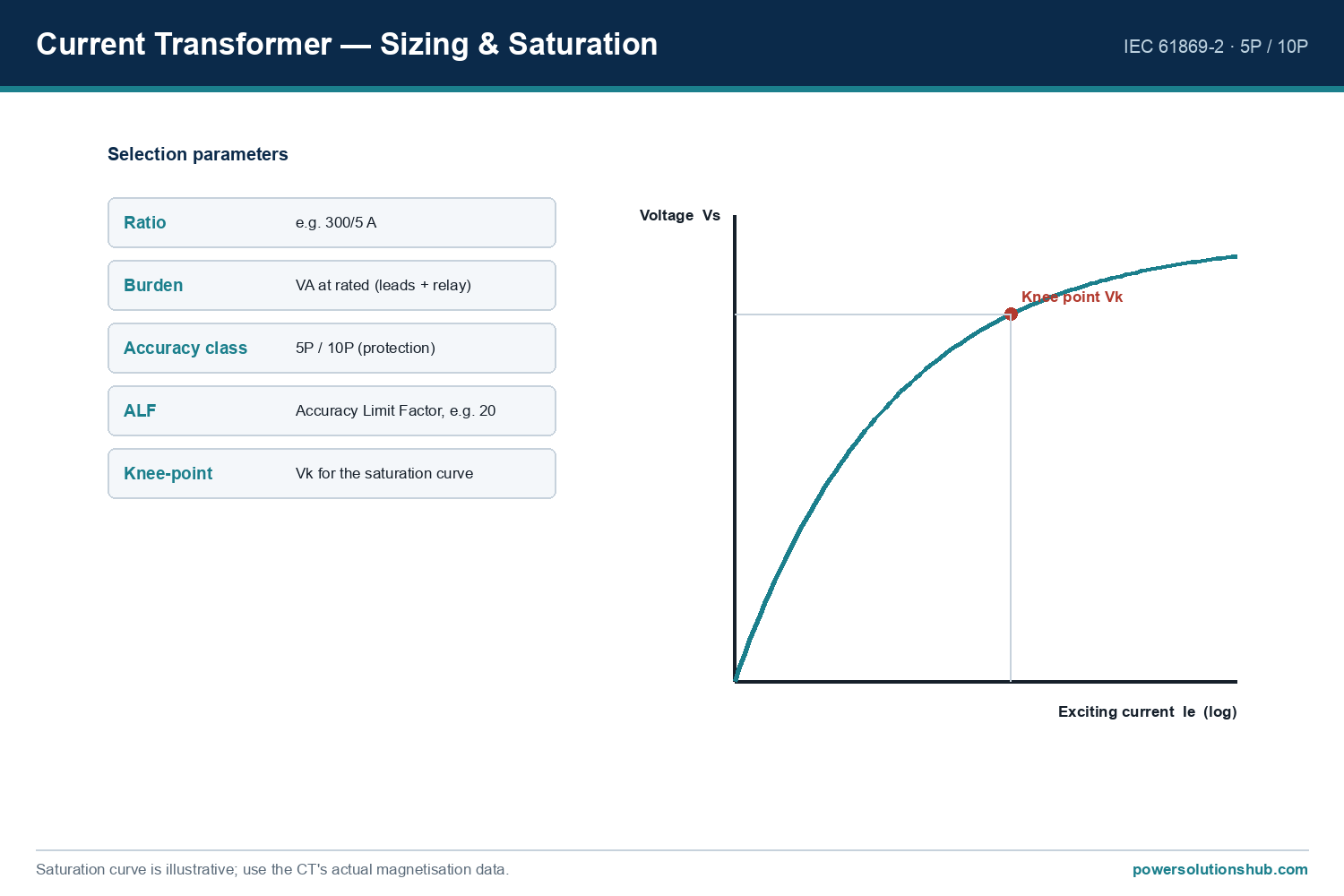
- CT accuracy and saturation. Current transformer class and knee-point voltage affect measured fault current accuracy, especially for high-magnitude faults; undersized CTs can distort grading margins.
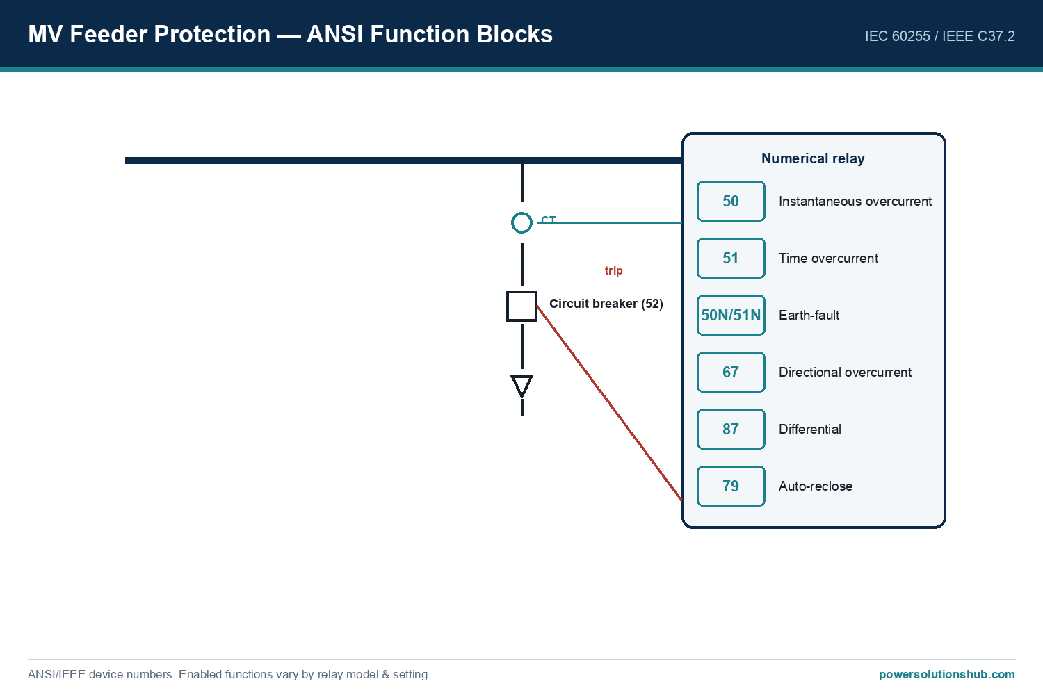
- Directional and differential elements. In looped or parallel-fed networks, plain time-graded overcurrent relaying may not achieve selectivity; directional overcurrent or unit protection (differential) schemes are then required.
- Breaker interrupting time and relay overshoot. The grading margin must always account for the actual breaker clearing time and the specific relay’s overshoot/reset characteristics rather than a single assumed constant across all equipment.
- Common pitfalls: neglecting motor starting or transformer inrush current when setting pickup (causing nuisance trips); ignoring changes in fault level after network reconfiguration; failing to re-run the grading study after equipment upgrades; and copying settings from one project to another without re-validating fault levels and CT ratios.
Coordination studies are typically documented for the full protection scheme covering incoming transformer relays, busbar protection, and outgoing feeder relays within [medium voltage switchgear](https://powersolutionshub.com/what-is-mv-switchgear-medium-voltage-switchgear/) assemblies, and settings are implemented on numerical protection relays associated with each circuit breaker, including those protecting distribution transformers.
Standards governing protection coordination
The characteristic curve equations and terminology used above follow IEC 60255-151 (Functional requirements for over/under current protection), which defines the standard inverse, very inverse, and extremely inverse time-current formulas used in coordination studies. IEEE C37.112 provides the equivalent standard inverse-time characteristics used in IEEE-based (ANSI) grading practice, particularly relevant where TDS (time dial setting) terminology is used instead of TMS. Overall protective relaying system requirements are also addressed in IEEE C37.90 and related application guides. Coordination studies for the associated switching equipment must also reflect the short-circuit withstand and breaking capability of the switchgear per IEC 62271-100/200, since relay time settings must never exceed the equipment’s rated short-time withstand duration.
Related guides
See also our guides on gas-insulated switchgear, ring main units and metal-clad switchgear.
What is the difference between protection coordination and selectivity?
The terms are largely synonymous in practice: coordination describes the calculation process (setting pickup and time delays), while selectivity describes the resulting outcome — only the relay nearest the fault trips, minimizing the de-energized area.
What is TMS or TDS in a protection relay?
TMS (Time Multiplier Setting, IEC terminology) or TDS (Time Dial Setting, IEEE terminology) is a multiplier applied to the base inverse-time curve equation, allowing the same curve shape to be shifted in time so that relays at different network positions can be graded against one another.
How much grading margin should be used between two relays?
The margin must cover breaker interrupting time, relay overshoot, and measurement tolerance; a commonly applied design range is roughly 0.3–0.5 seconds, but the exact value should be validated against the specific relay and breaker performance data for the project rather than assumed universally.
Why is a standard inverse curve used in the worked example instead of definite time?
Inverse-time curves automatically clear high-magnitude faults faster and low-magnitude faults slower, which naturally supports selectivity across a range of fault levels without needing a separate time setting for every fault scenario, unlike a fixed definite-time delay.
Do differential relays need time-current grading like overcurrent relays?
No. Differential (unit) protection compares currents at both ends of a protected zone and operates nearly instantaneously for an internal fault, independent of downstream relay settings, so it does not require time-graded coordination with other relays in the same way overcurrent schemes do.
What happens if two relays are not properly coordinated?
Poor coordination can cause both the primary and backup relay to trip simultaneously for the same fault (loss of selectivity, unnecessarily wide outage), or cause excessive fault clearance delay that increases thermal stress on cables and switchgear and raises arc-flash incident energy.
Does network reconfiguration affect an existing coordination study?
Yes. Any change in source impedance, transformer sizing, cable routing, or the addition of parallel feeders alters fault current magnitudes at every point in the network, so the grading study and relay settings must be reviewed and re-verified after such changes. “`
Looking for medium voltage protection relays?
Looking for high-quality medium voltage protection relays? We provide expert engineering support and reliable products for all your medium voltage needs.
For quotations and requests: info@electricistanbul.com
WhatsApp: +90 501 076 69 91