

Cable jointing and termination faults are electrical failures that originate at the accessory point where a medium-voltage (MV) power cable is joined to another cable section or connected to switchgear, transformers, or overhead lines, and they are most often triggered by localized electric field concentration, partial discharge, moisture ingress, or defective workmanship rather than by the cable insulation itself. Because the cut end of a cable interrupts the uniform coaxial field that exists along its length, accessories are inherently the weakest electrical point in any MV circuit, and understanding the underlying field physics is essential for specifying, installing, and testing joints and terminations correctly. This guide works through the governing formulas, a fully computed example, a comparison of accessory types, and the IEC/IEEE framework that governs design and testing — relevant across every export market we serve, including the Middle East and Gulf (including Egypt and Saudi Arabia), North Africa, the CIS region, and Sub-Saharan Africa, where dust pollution, heat cycling, and humidity each place different demands on accessory selection.
Why Jointing and Termination Faults Matter
Along an intact cable run, the semi-conductive screen keeps the electric field radially symmetric and confined within the insulation. At a joint or termination, that screen is cut and removed over a short length to expose the conductor, which creates a sharp discontinuity: field lines that were previously contained now try to escape along the insulation surface, producing a tangential stress component that did not exist before. If this stress is not controlled, it leads to partial discharge (PD), tracking along the interface, localized overheating at crimped or bolted connections, and — over months or years — a flashover or thermal runaway failure. Because joints and terminations concentrate stress that the rest of the cable does not see, a very large share of MV cable circuit failures reported in field studies trace back to the accessory rather than to the cable body itself, which is why accessory design, installation quality, and post-installation testing deserve engineering attention equal to — or greater than — that given to the cable selection described on our [medium voltage switchgear](/what-is-mv-switchgear-medium-voltage-switchgear/) and distribution transformer hub pages.
The Method: Electric Field and Stress-Control Formulas
Radial field in coaxial cable insulation
For a single-core cable with conductor radius r_c and insulation outer radius r_i, operating at phase-to-ground voltage U₀, the radial electric field at radius r follows the classical coaxial-capacitor formula:
E(r) = U₀ / [r × ln(r_i / r_c)]
The field is highest at the conductor surface (r = r_c) and falls off logarithmically toward the outer screen. This formula is the starting point for sizing insulation thickness and for predicting where stress will concentrate once the screen is cut back at a joint or termination.
Stress-cone / stress-control design
At a termination, the cut edge of the semi-conductive screen behaves like a sharp metallic edge sitting in a dielectric, which drives local field enhancement far beyond the bulk value given by the formula above. Two engineering methods bring this back under control:
- Geometric (capacitive) stress control — a cone-shaped insulating body that gradually increases the effective insulation thickness at the screen cut-back point, spreading the field over a longer path (the classical “stress cone”).
- Refractive (resistive/capacitive) stress control — a tube or mastic with a non-linear or high-permittivity material that electrically “smooths” the discontinuity without a large physical cone, commonly used in heat-shrink and cold-shrink kits.
Short-circuit thermal withstand at the joint
A joint or termination must also survive the fault current that could pass through it before protection operates. The standard thermal short-circuit formula for conductors (the basis of IEC 60949) is:
S = I × √t / k
where S is the minimum conductor cross-section (mm²), I is the fault current (A), t is the fault clearance time (s), and k is a material constant (for copper conductors, k is commonly taken around 143 for XLPE-insulated cable under adiabatic short-circuit conditions). This same relationship is used to check that the jointing sleeve, compression lug, and connecting ferrule are not the limiting link in the fault-current path.
Worked Example: Stress, Creepage, and Fault Withstand at an 11 kV Termination
Step 1 — Maximum electric stress at the conductor. Take an 11 kV cable (U₀ ≈ 6.35 kV phase-to-ground), with an illustrative conductor radius r_c = 10 mm and insulation outer radius r_i = 20 mm.
E_max = U₀ / [r_c × ln(r_i / r_c)] = 6,350 / [0.01 × ln(2)] = 6,350 / (0.01 × 0.693) ≈ 916,300 V/m ≈ 0.92 kV/mm
This is the design-point stress the stress cone or heat-shrink stress tube at the termination must manage without initiating partial discharge.
Step 2 — Creepage distance for the environment. IEC 60815 defines specific creepage distance as a function of pollution severity, expressed in mm per kV of system voltage. For a 12 kV-class termination:
- Light pollution (class a, ≈16 mm/kV): L = 12 × 16 = 192 mm
- Heavy pollution — e.g. coastal/desert dust environments common across the GEO region (class d, ≈31 mm/kV): L = 12 × 31 = 372 mm
This nearly doubled creepage requirement is exactly why terminations installed in high-dust or high-salinity sites need longer insulator sheds or silicone outdoor terminations rather than a standard indoor kit — a selection error here is one of the most frequent root causes of flashover faults in the field.
Step 3 — Minimum joint conductor section for a fault. For a prospective fault current I = 20 kA cleared in t = 0.5 s, with copper and k ≈ 143:
S = I × √t / k = 20,000 × √0.5 / 143 = 20,000 × 0.707 / 143 ≈ 98.9 mm²
If the jointing ferrule or compression lug at the accessory has a smaller effective cross-section than this, it — not the cable — becomes the thermal weak point during a through-fault, even if the joint tested fine at rated load current.
Comparison of Common MV Jointing and Termination Methods
| Accessory type | Stress-control principle | Typical strength | Typical vulnerability |
|---|---|---|---|
| Heat-shrink termination/joint | Refractive stress tube (resistive/capacitive coating) | Fast installation, flexible, widely stocked | Sensitive to surface prep and shrink temperature control |
| Cold-shrink termination/joint | Pre-expanded elastomeric sleeve, no open flame | Safer installation in confined/hazardous areas | Requires correct tube removal sequence; sleeve relaxation if oversized |
| Push-on separable connector (plug-in bushing) | Factory-molded geometric stress cone | Fully enclosed, very low PD risk when correctly mated | Needs matched interface tolerance to switchgear bushing |
| Resin/epoxy-filled joint | Cast resin body embedding factory or field stress control | Robust sealing against moisture ingress | Longer cure/installation time; sensitive to resin mixing errors |
| Taped/hand-built joint (legacy, paper-insulated lead-covered cables) | Manually built field grading with tapes | Can be repaired almost anywhere | Highly dependent on installer skill; higher failure incidence |
Selection Criteria and Field Pitfalls
Match the accessory to the cable insulation system. A kit designed for XLPE cable will not necessarily grade the field correctly on paper-insulated lead-covered (PILC) cable, and vice versa; always confirm insulation type, not just voltage class.
Size creepage distance to the pollution environment, not just the rated voltage, as shown in the worked example — this is the single most common cause of outdoor termination flashover in hot, dusty, or coastal GEO markets.
Allow for thermal cycling. Conductors and sleeves expand and contract with load cycling; joints must accommodate this movement without loosening torque on connectors or disturbing the stress-control interface.
Control cable screen bonding. Screens must be grounded with a defined bonding method (single-point, both-ends, or cross-bonded) appropriate to circuit length and fault levels; incorrect bonding causes circulating currents, screen overheating, and accelerated insulation aging at the termination.
Use the correct crimping/compression tooling and die set matched to the connector and conductor size; under- or over-compression is a leading cause of hot-spot failures discovered later by thermography.
Commission with electrical testing, not just visual inspection. Very low frequency (VLF) withstand testing, tan-delta/dissipation factor measurement, and partial discharge (PD) testing are the recognized methods for detecting a latent jointing or termination defect before it becomes an in-service failure — complementing protection schemes covered on our [protection relay](/what-is-a-medium-voltage-protection-relay-mv-protection-relay/) hub page, which clear the fault but cannot prevent a weak accessory from failing again.
Governing Standards
MV cable accessory design, materials, and type testing are addressed by IEC 60502 (power cables with extruded insulation, rated voltages up to 30 kV) and IEC 60840 (extruded cables for higher voltage ranges), while IEC 60229 covers tests on cable oversheaths used for jointing/sealing integrity. Thermal short-circuit withstand calculations for cables and accessory conductors follow IEC 60949. Selection of creepage distance for polluted environments follows IEC 60815, and high-voltage withstand/PD test procedures reference IEC 60060. In North American and related export practice, IEEE 48 governs test procedures for AC cable terminations and IEEE/ANSI 404-aligned practice covers cable joints. Always confirm the applicable standard against the specific cable insulation system and voltage class before accepting a jointing or termination design.
Related guides
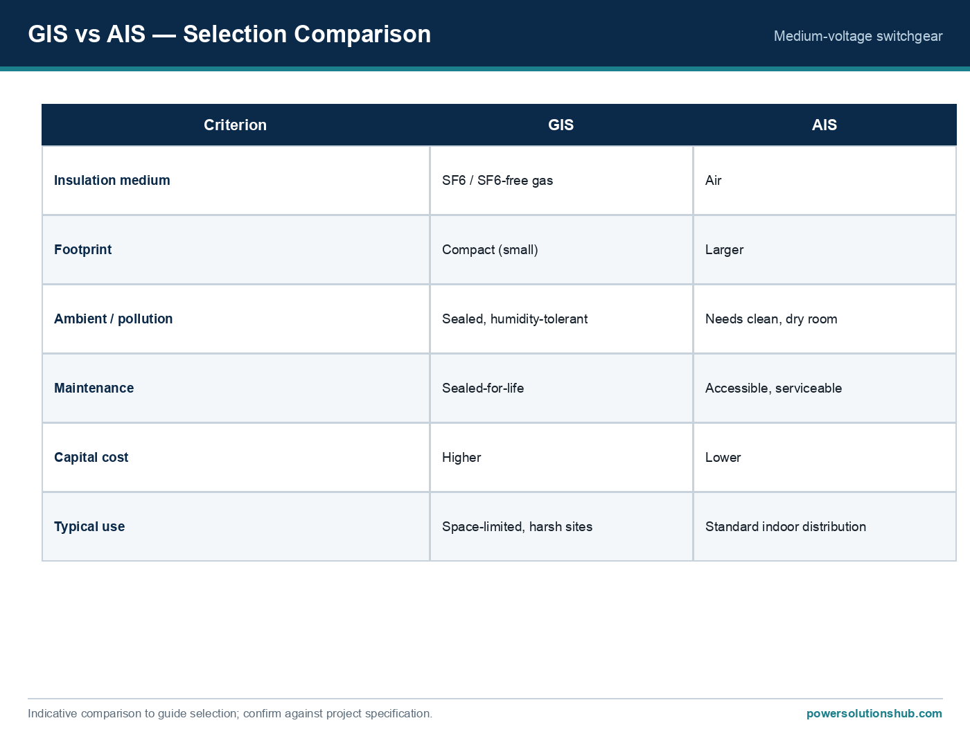
See also our guides on gas-insulated switchgear, ring main units and metal-clad switchgear.
What is the most common root cause of MV cable jointing faults?
Uncontrolled electric field concentration at the screen cut-back point — usually from incorrect stress-cone positioning, contaminated or poorly prepared cable surfaces, or mismatched kit selection — is the most frequently cited root cause, often confirmed afterward by partial discharge analysis.
How is electric stress at a termination calculated?
Using the coaxial field formula E(r) = U₀ / [r × ln(r_i/r_c)], which gives the radial stress inside the insulation; the actual peak at the screen cut edge is higher and is why dedicated stress-control geometry or material is required.
Why does pollution level change the required creepage distance?
IEC 60815 defines specific creepage distance in mm/kV according to pollution severity class; heavier pollution (dust, salt deposits) requires a longer surface leakage path to avoid flashover, as shown in the worked example above.
Can a joint or termination be the weak point during a fault even if it is fine at normal load?
Yes — the thermal short-circuit formula S = I√t/k shows that connectors and ferrules need their own cross-sectional adequacy check against the prospective fault current and clearance time, independent of their continuous current rating.
What tests detect a latent jointing fault before failure?
VLF withstand testing, tan-delta (dissipation factor) measurement, and partial discharge testing are the standard diagnostic methods for verifying accessory integrity after installation.
Is screen bonding relevant to jointing faults?
Yes — incorrect single-point versus cross-bonding arrangements can induce circulating currents in the screen, causing localized heating precisely at the joint or termination point.
Do heat-shrink and cold-shrink kits perform the same stress-control function?
Both use refractive (resistive/capacitive) stress control rather than a large geometric cone, but they differ in installation method — heat-shrink requires controlled heating while cold-shrink uses a pre-stretched sleeve removed over the cable, which is preferred in hazardous or confined installation areas.
Looking for medium voltage cable terminations?
Looking for high-quality medium voltage cable terminations? We provide expert engineering support and reliable products for all your medium voltage needs.
For quotations and requests: info@electricistanbul.com
WhatsApp: +90 501 076 69 91