

Transformer differential protection (ANSI device 87T) is a unit protection scheme that compares current entering and leaving a power transformer winding-by-winding to instantaneously detect internal faults, while restricted earth fault protection (REF, device 87N/64REF) adds sensitive coverage for earth faults near the neutral point that differential protection alone cannot reliably detect. This guide walks engineers and specifiers through the operating principle, the governing formulas, a fully worked numerical example for a two-winding transformer, CT selection pitfalls, and the standards that govern relay application. It is written for utility, EPC, and industrial engineers specifying protection schemes for medium-voltage transformers across the Middle East and Gulf region (including Egypt and Saudi Arabia), North Africa, the CIS, and Sub-Saharan Africa, where transformer protection is typically paired with medium-voltage switchgear and numerical protection relays at the incoming and outgoing bays.
Why Differential and REF Protection Matter
A power transformer is one of the most capital-intensive and longest lead-time assets in a substation. An internal winding fault — turn-to-turn, phase-to-phase, or phase-to-earth inside the tank — can escalate within milliseconds into catastrophic core and tank damage, oil fire risk, and extended downtime measured in months rather than days. Overcurrent relays on the incoming feeder are too slow and too insensitive for this class of fault because they must be graded with downstream devices and cannot “see” a low-magnitude internal fault that does not raise line current enough to operate.
Differential protection solves this by comparing currents at every terminal of the protected zone using Kirchhoff’s current law: in healthy operation, the vector sum of currents entering and leaving the transformer (referred to a common base) is zero. Any internal fault breaks that balance and produces a differential current that the relay uses to trip instantaneously, without any time-grading delay. REF protection extends this principle specifically to the transformer neutral-earthing circuit, where it is the most sensitive method available for detecting low-level earth faults close to the star point — faults that produce a very small line current but can still damage the winding.
The Method and Governing Formulas
Basic differential principle
For a two-winding transformer with primary current I1 and secondary current I2 (both referred to the same base via CT ratios and vector-group compensation), the relay computes:
- Differential (operating) current: Id = |I1 − I2|
- Restraint (bias) current: Ir = (I1 + I2) / 2
In a healthy transformer carrying load current, Id should be close to zero (small residual mismatch from CT errors and tap-changer position). The relay trips when Id exceeds a bias-dependent threshold defined by a dual-slope characteristic: a sensitive pickup near no-load, and a progressively higher percentage slope at higher restraint currents to tolerate CT saturation and on-load tap-changer (OLTC) mismatch during external faults and heavy through-load.
CT ratio and vector-group matching
Before any differential calculation, the relay (or in older schemes, interposing CTs) must correct for two sources of mismatch:
- Turns ratio mismatch — the transformer’s primary and secondary rated currents differ because of the voltage transformation ratio, so CT ratios on each side must be chosen so that secondary currents are nominally balanced at rated load.
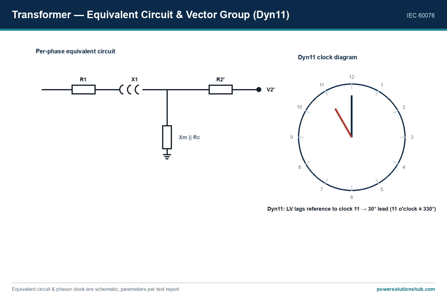
- Vector-group phase shift — a Dyn11 or similar transformer introduces a 30° (or multiple of 30°) phase shift between primary and secondary currents. Modern numerical relays perform this compensation digitally; older electromechanical and static schemes required physically wired interposing CTs in delta/star configuration.
Rated current formula
The starting point for any CT and setting calculation is the transformer’s rated current on each winding:
I = S / (√3 × V)
where S is the rated apparent power (VA) and V is the rated line voltage (V) of that winding.
Worked Example: 10 MVA, 33/11 kV Transformer
Consider a 10 MVA transformer with an HV winding rated at 33 kV and an LV winding rated at 11 kV, connected Dyn11.
Step 1 — Rated currents on each side
HV side: I(HV) = 10,000,000 / (1.732 × 33,000) ≈ 174.9 A
LV side: I(LV) = 10,000,000 / (1.732 × 11,000) ≈ 524.9 A
Step 2 — CT ratio selection
CTs are normally selected with a primary rating somewhat above the transformer’s rated current, using standard ratios available from the manufacturer’s range. For this example, assume:
- HV-side CT ratio: 200/1 A
- LV-side CT ratio: 600/1 A
Step 3 — Secondary (relay input) currents at rated load
HV side: 174.9 / 200 ≈ 0.875 A LV side: 524.9 / 600 ≈ 0.875 A
Because the two CT ratios were chosen deliberately to balance the secondary currents, the relay sees almost equal magnitudes from both sides at rated load — exactly what is needed before the vector-group and phase-shift compensation is applied digitally inside the relay.
Step 4 — Differential and restraint current at full load (healthy condition)
Id = |0.875 − 0.875| = 0 A (ignoring small CT accuracy-class errors) Ir = (0.875 + 0.875) / 2 = 0.875 A
Step 5 — Illustrative pickup and slope setting
A typical numerical relay bias characteristic (illustrative, for teaching the concept — actual settings are project-specific and configured per relay manufacturer instructions) might use:
- Minimum pickup: a small fraction of rated secondary current, e.g. around 0.2–0.3 A in this example, to ride through normal CT mismatch and magnetising inrush
- First slope: a modest percentage of restraint current up to roughly twice rated current, to tolerate OLTC mismatch
- Second, steeper slope above that point, to remain stable during heavy through-faults where CT saturation is more likely
Step 6 — Internal fault scenario
Suppose an internal fault causes the HV side to feed 150 A (primary) into the fault while the LV side, if the fault is close to the HV terminals, contributes very little or current flows the “wrong” way. Referred through the CT ratio, this produces a large Id relative to Ir, far above the bias threshold, and the relay trips instantaneously — demonstrating the core value of unit protection versus time-graded overcurrent protection.
Restricted Earth Fault (REF) Worked Concept
REF protection compares the current measured by a CT in the transformer neutral-to-earth connection with the vectorial sum of the three phase CTs on the same winding. In healthy operation and even during external earth faults, these two quantities should balance (an external fault current flows through the phase CTs and the neutral CT equally and cancels in the REF comparison). An internal earth fault on that winding — even one too small for ordinary overcurrent or line differential protection to detect — unbalances this comparison and the REF element operates.
A key design rule: the neutral CT and the three phase CTs used for REF must have matching ratios and similar magnetising characteristics, otherwise spurious differential current appears during heavy through-faults and either causes false trips or forces the setting to be desensitised, defeating the purpose of REF’s high sensitivity. This is why REF is usually specified as a dedicated, separately wired scheme rather than being derived mathematically inside the main 87T differential algorithm.
Selection and Comparison Table
| Aspect | Overall (87T) Differential | Restricted Earth Fault (87N/64REF) |
|---|---|---|
| Fault types detected | Phase-phase, phase-earth, turn-to-turn (large) | Earth faults near winding/neutral, including low-magnitude |
| Sensitivity to earth faults | Moderate (depends on fault location) | High — most sensitive earth-fault protection available |
| CT requirement | CTs at each transformer terminal, ratio-matched per side | Matched-ratio CTs: neutral CT + sum of phase CTs on one winding |
| Vector-group compensation | Required (digital or interposing CT) | Not required — scheme is inherently per-winding |
| Typical speed | Instantaneous (no grading delay) | Instantaneous (no grading delay) |
| Stability concern | CT saturation on heavy through-faults; OLTC mismatch | CT ratio/characteristic mismatch between neutral and phase CTs |
| Common relay standard reference | IEEE C37.91 guidance; IEC 60255 relay performance | IEEE C37.91 guidance; IEC 60255 relay performance |
Selection Criteria and Common Pitfalls
- CT accuracy class and knee-point voltage: differential and REF schemes demand CTs with adequate knee-point voltage to avoid saturation during close-in through-faults; undersized CTs are a leading cause of nuisance tripping.
- Vector group and phase compensation: always confirm the relay’s vector-group compensation setting matches the actual transformer connection (e.g., Dyn11) — a mismatch produces a permanent spurious differential current that masks genuine faults or causes standing trips.
- Tap-changer range: the differential bias slope must accommodate the full OLTC tap range, since the apparent mismatch between HV and LV currents changes as the transformer moves off its nominal tap.
- Inrush restraint: transformer energisation produces a large magnetising inrush current rich in second-harmonic content; the relay’s inrush (harmonic restraint or blocking) function must be correctly enabled and set to avoid false trips on energisation.
- REF CT matching: as noted above, neutral and phase CTs feeding the REF element must be ratio- and characteristic-matched; mixing CT types or ratios is a frequent field error.
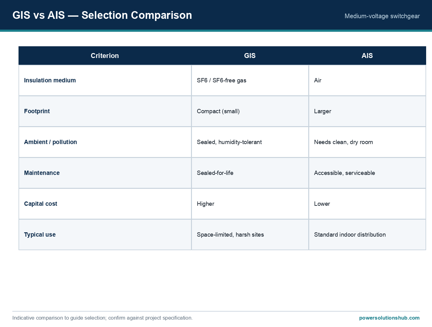
- Coordination with switchgear and other protection layers: differential and REF trip the associated circuit breakers in the switchgear on both sides of the transformer; protection engineers should review this alongside the switchgear protection and control philosophy when selecting protection relays.
Standards and References
Application of transformer differential and restricted earth fault protection is most commonly guided by IEEE C37.91 (Guide for Protective Relay Applications to Power Transformers), which addresses CT selection, bias settings, inrush restraint, and REF scheme design in detail. The performance characteristics of the numerical protection relays implementing these functions are governed by IEC 60255 (measuring relays and protection equipment). The transformer itself, including its vector group, rated power, and insulation levels used as inputs to these calculations, is specified per IEC 60076 (power transformers). Where the relay communicates via a substation automation network, IEC 61850 governs the data modelling and communication interface. Project-specific settings should always be finalised using the actual transformer nameplate data, CT test certificates, and the selected relay manufacturer’s setting guide.
Related guides
See also our guides on gas-insulated switchgear, ring main units and metal-clad switchgear.
What is the difference between transformer differential protection and restricted earth fault protection?
Differential protection (87T) compares currents at all transformer terminals to detect most internal fault types, while REF (87N/64REF) is a dedicated, more sensitive scheme focused specifically on earth faults near one winding’s neutral point, which ordinary differential protection may not detect reliably at low fault currents.
Why do transformer differential relays need harmonic (inrush) restraint?
Energising a transformer produces a magnetising inrush current that looks like a large differential current to the relay but is not a fault. Harmonic restraint, typically based on second-harmonic content, allows the relay to distinguish inrush from genuine internal faults and avoid a false trip.
Why must CT ratios be matched on each side of the transformer for differential protection?
Because the primary and secondary rated currents of a transformer differ according to the voltage ratio, CT ratios must be chosen so that the secondary currents fed to the relay are close to balanced at rated load; otherwise the relay sees a permanent false differential current.
Does vector group affect differential protection settings?
Yes. A transformer vector group such as Dyn11 introduces a phase shift between HV and LV currents that must be compensated, either digitally inside a numerical relay or historically via interposing CTs, before the differential comparison is valid.
Can restricted earth fault protection detect faults that differential protection misses?
Yes — REF is specifically designed to be more sensitive to low-magnitude earth faults near the transformer neutral than the overall differential scheme, making the two protections complementary rather than redundant.
What standard governs the application of transformer differential and REF protection?
IEEE C37.91 is the primary application guide for protective relaying of power transformers, while the relay hardware performance follows IEC 60255 and the transformer itself is specified per IEC 60076.
Where should differential and REF relays be applied relative to the switchgear?
The current transformers and trip outputs for 87T and REF schemes are coordinated with the circuit breakers in the medium-voltage switchgear on each side of the transformer, so protection relay settings should be reviewed together with the overall switchgear protection and control architecture.
Looking for medium voltage transformers?
Looking for high-quality medium voltage transformers? We provide expert engineering support and reliable products for all your medium voltage needs.
For quotations and requests: info@electricistanbul.com
WhatsApp: +90 501 076 69 91