

An LV switchboard is a low-voltage power distribution assembly — typically rated up to 1000 V AC — that houses busbars, circuit breakers, fuses, and protection/metering devices used to distribute electrical energy safely from a transformer or generator to downstream loads. LV switchboard maintenance is the structured, standards-based program of inspection, testing, and corrective action that keeps that assembly within its designed thermal, dielectric, and mechanical limits throughout its service life. This guide walks through how faults originate, the first-principles formulas engineers use to quantify risk, a fully worked numerical example, a practical comparison table of fault types, and the governing IEC framework. It is written for utility, industrial, and EPC engineers working across the Middle East and Gulf region (including Egypt and Saudi Arabia), North Africa, the CIS states, and Sub-Saharan Africa, where high ambient temperatures, dust ingress, and variable grid quality accelerate many of the failure modes described below.
Why LV Switchboard Faults Matter
Unlike medium-voltage switchgear, LV switchboards are often located close to operators, inside plant rooms, or embedded in production lines — so a fault here has a direct and immediate safety consequence, not just a reliability one. The dominant failure mechanisms are:
- Thermal failure — loose or corroded connections increase contact resistance, raising local temperature until insulation degrades or the joint arcs.
- Insulation breakdown — moisture ingress, dust tracking, or aged insulation lowers the insulation resistance below a safe threshold, eventually causing a phase-to-earth or phase-to-phase fault.
- Mechanical fatigue — vibration loosens busbar bolts and terminal lugs over years of thermal cycling.
- Overload/short-circuit stress — repeated fault-current let-through without proper coordination damages breaker contacts and busbar supports.
- Arc flash events — the most severe outcome, where a fault escalates into a sustained internal arc, releasing thermal energy that can be catastrophic to nearby personnel.
Because these failure modes are progressive, most of them are detectable — and preventable — with the right calculation-based inspection program, rather than reactive repair after a trip or burn-out.
The Method: Core Diagnostic Formulas
Three calculations form the backbone of LV switchboard fault analysis and maintenance planning.
1. Rated/load current (baseline for thermal assessment)
For a three-phase system:
I = S / (√3 × V)
where S is apparent power (kVA) and V is line voltage (kV or V). This is the reference current against which thermal imaging and loading studies are compared.
2. Prospective short-circuit current at the switchboard
Isc = V / (√3 × Ztotal)
where Ztotal is the total impedance (transformer + cable + busbar) referred to the LV side, in ohms. This value determines the required breaking capacity of the incoming breaker and the mechanical withstand of the busbar.
3. Joint heating from contact resistance (I²R loss)
P = I² × R
A joint with elevated resistance R dissipates power as heat; sustained operation above the conductor’s thermal class accelerates insulation aging approximately in line with the Arrhenius relationship — every rise of about 8–10 °C above rated operating temperature can roughly halve insulation life, which is why thermographic surveys are a cornerstone of preventive maintenance.
Worked Example: From Transformer Rating to Fault Risk
Consider a 1000 kVA, 11 kV/0.4 kV distribution transformer feeding an LV switchboard.
Step 1 — Rated LV current
I = S / (√3 × V) = 1,000,000 / (1.732 × 400) ≈ 1,443 A
This is the current the LV switchboard’s incoming breaker and busbar must carry continuously under full load.
Step 2 — Transformer impedance voltage
Assume the transformer has a typical impedance voltage of 6% (a common nameplate value for this class of transformer). The transformer’s LV-side impedance is:
Zt = (Uz% / 100) × (V² / S) = 0.06 × (400² / 1,000,000) = 0.06 × 0.16 = 0.0096 Ω
Step 3 — Prospective short-circuit current
Isc = V / (√3 × Zt) = 400 / (1.732 × 0.0096) ≈ 24,040 A ≈ 24 kA
This illustrative figure (ignoring upstream and cable impedance, which would reduce it slightly) tells the engineer that the LV switchboard’s main breaker and busbar bracing must be selected with a short-circuit withstand comfortably above this prospective value, with margin for decrement and asymmetry.
Step 4 — Heating from a degraded joint
Suppose thermal imaging on a busbar joint carrying the full 1,443 A load shows a calculated contact resistance of 0.00005 Ω (50 µΩ) due to surface oxidation, versus a healthy joint resistance of 0.00001 Ω (10 µΩ).
- Healthy joint: P = I² × R = 1,443² × 0.00001 ≈ 20.8 W
- Degraded joint: P = 1,443² × 0.00005 ≈ 104 W
A five-fold increase in dissipated power at the same load current is exactly the signature that infrared thermography is designed to catch before the joint reaches a damaging temperature — long before an overcurrent relay would ever see an abnormal reading, because the load current itself hasn’t changed.
This sequence — rated current → fault current → joint heating — is the logical backbone of any LV switchboard condition assessment and should sit alongside protection coordination studies referenced on our [protection relay](/what-is-a-medium-voltage-protection-relay-mv-protection-relay/) and switchgear resource pages.
Fault Types, Detection Methods, and Typical Actions
| Fault type | Root cause | Detection method | Typical corrective action |
|---|---|---|---|
| Loose/high-resistance joint | Vibration, improper torque, oxidation | Infrared thermography, contact resistance (micro-ohmmeter) test | Clean, re-torque to specified value, re-test |
| Insulation degradation | Moisture, dust, aging, tracking | Insulation resistance (megohmmeter) test, partial discharge survey | Clean/dry compartment, replace insulation, improve sealing |
| Busbar mechanical fatigue | Thermal cycling, vibration, inadequate bracing | Visual/mechanical inspection, torque check | Re-brace, replace fasteners, verify short-circuit withstand design |
| Overload tripping | Load growth beyond design current | Load current logging vs. rated I | Load redistribution, upsize feeder/breaker |
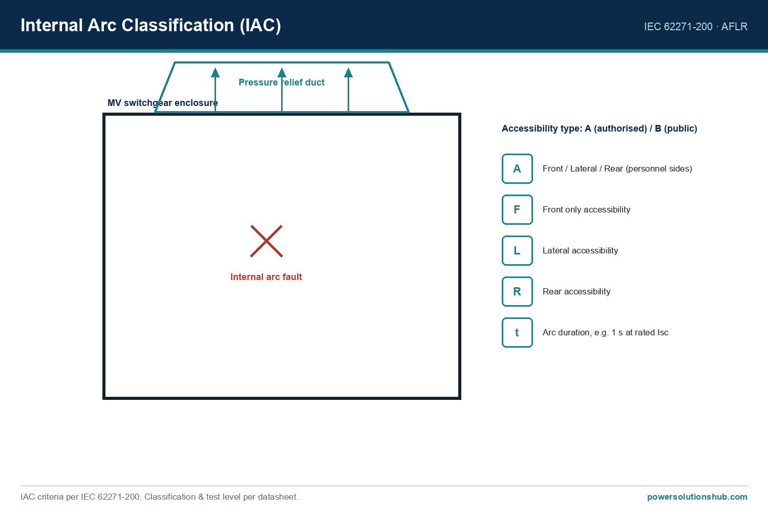
| Internal arc fault | Combination of the above + ingress of conductive debris | Arc-fault detection relays, post-event inspection | Isolate, replace damaged sections, review internal arc classification (IAC) design |
| Corrosion of enclosure/contacts | Humidity, coastal/desert dust environments | Visual inspection, IP rating verification | Improve ventilation/filtration, corrosion-resistant plating |
Selection Criteria & Common Pitfalls in Maintenance Programs
- Set maintenance intervals by risk, not calendar alone. Switchboards in harsh ambient conditions (high dust, humidity, or heavy load cycling common across Gulf and African sites) warrant shorter thermographic and torque-check intervals than clean, climate-controlled plant rooms.
- Always de-energize and lock out before mechanical torque checks — thermography can be done live, but tightening bolts cannot.
- Don’t rely on overcurrent protection to catch joint heating. As the worked example shows, a degraded joint can dissipate several times more heat at the same load current, which a thermal-overload relay will not detect until much later.
- Track trends, not single readings. A single insulation resistance test is a snapshot; recording values over successive outages reveals the rate of degradation and lets you forecast remaining service life.
- Verify short-circuit withstand after any load growth. If downstream load increases, re-run the Isc calculation — a switchboard sized correctly at commissioning may be under-protected years later if upstream transformer capacity was upgraded.
- Coordinate arc-flash risk assessments with protection settings. Reducing fault clearing time through better relay coordination is often the most cost-effective way to lower incident energy exposure.
- Don’t ignore ambient derating. High ambient temperature reduces the effective current-carrying capacity of busbars and cables feeding the switchboard, which should be reflected in the baseline rated-current assumption used for thermography pass/fail limits.
Governing Standards
LV switchboard design and verification is governed primarily by the IEC 61439 series (“Low-voltage switchgear and controlgear assemblies”), which defines design verification, including temperature-rise and short-circuit withstand verification, for the assembly as a whole. Ongoing inspection and periodic testing of the installation fall under IEC 60364-6 (verification of electrical installations), while individual low-voltage switching and protective devices within the board are covered by IEC 60947. Where internal arc performance is a design consideration, the assembly’s internal arc classification should be evaluated against the relevant clauses of IEC 61439. Personnel safety during live diagnostic work (such as thermography) should follow site electrical safety procedures aligned with these IEC assembly and installation standards.
Related guides
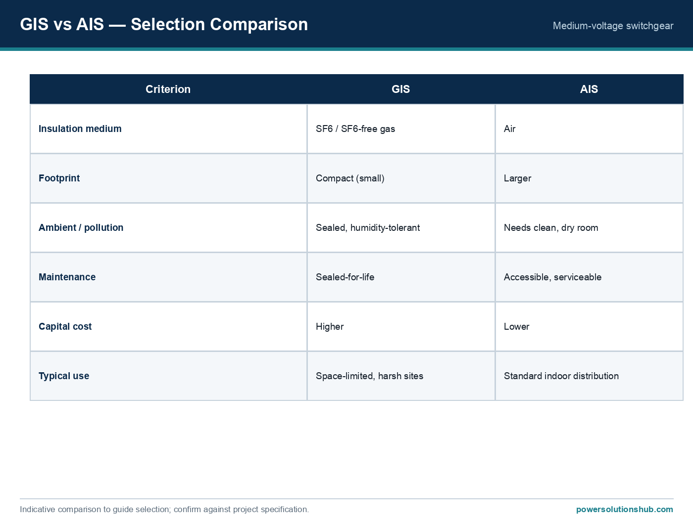
See also our guides on gas-insulated switchgear, ring main units and metal-clad switchgear.
How often should an LV switchboard be inspected?
Inspection frequency should be based on criticality, ambient severity, and load profile rather than a fixed calendar rule — critical boards in harsh or dusty environments typically need more frequent thermographic and mechanical checks than lightly loaded boards in clean indoor plant rooms.
What is the single most useful diagnostic tool for LV switchboard maintenance?
Infrared thermography is widely regarded as the most cost-effective tool because it detects joint and contact degradation (via the I²R heating mechanism) long before it would trip a protection device or cause a visible fault.
How is the prospective short-circuit current at an LV switchboard calculated?
It is derived from the supply voltage divided by the total impedance from source to the board (Isc = V / (√3 × Ztotal)), as shown in the worked example above, and is used to verify that breakers and busbars have adequate short-circuit withstand.
Does increasing downstream load always require re-checking the switchboard?
Yes — any increase in connected load changes the rated current baseline used for thermal assessments and may also change upstream transformer or generator sizing, which directly affects the prospective short-circuit current the switchboard must withstand.
What causes most arc flash incidents in LV switchboards?
Most originate from a progressive fault — a loose connection, insulation failure, or contamination ingress — that escalates under load or during a switching operation, rather than from a single catastrophic event with no precursor.
Is insulation resistance testing enough to judge switchboard health?
No — insulation resistance testing addresses dielectric condition but should be combined with thermography (thermal/contact condition) and mechanical torque verification (connection integrity) for a complete picture.
What standard governs the design verification of LV switchboards?
The IEC 61439 series governs design verification of low-voltage switchgear and controlgear assemblies, including temperature-rise and short-circuit withstand verification, while IEC 60364-6 covers periodic inspection of the installed system.
Looking for low voltage switchgear?
Looking for high-quality low voltage switchgear? We provide expert engineering support and reliable products for all your medium voltage needs.
For quotations and requests: info@electricistanbul.com
WhatsApp: +90 501 076 69 91