
An MV switchgear single-line diagram (SLD) is a simplified electrical schematic that represents a three-phase medium-voltage distribution system as a single line, using standardized symbols for circuit breakers, disconnectors, busbars, transformers, and protection devices to show how power flows from the source to each load. This guide explains how to read an SLD, how to derive the rated currents and short-circuit values that size each panel, and how a typical incomer–busbar–feeder arrangement is documented for procurement, protection coordination, and commissioning. It is written for engineers and buyers across the Middle East and Gulf region including Egypt and Saudi Arabia, North Africa, CIS countries, and Sub-Saharan Africa, where MV single-line diagrams accompany almost every switchgear tender and substation design package.
Why the single-line diagram matters
The SLD is the reference document that ties together every other engineering deliverable for a substation: protection relay settings, cable sizing, transformer rating, switchgear panel selection, and interlocking logic all trace back to what is drawn on this one page. A reviewer — whether a utility engineer, an EPC contractor, or a switchgear panel manufacturer — uses the SLD to verify:
- how many incomers, bus-couplers, and feeders exist and how they are arranged (single busbar, double busbar, ring main);
- the rated voltage and rated current of each section of busbar and each feeder;
- the rated short-circuit breaking current required from each circuit breaker;
- where protection relays, current transformers (CTs), and voltage transformers (VTs) are installed;
- how earthing, interlocking, and bus-transfer schemes are implemented.
Because the SLD condenses all this into symbols and a handful of numbers, misreading it — or specifying equipment without recalculating those numbers for the actual load — is one of the most common causes of under-rated switchgear orders. Understanding the underlying formulas removes that risk. For background on the panels themselves, see our [medium voltage switchgear](/what-is-mv-switchgear-medium-voltage-switchgear/) hub page, and for the devices shown at each breaker, our protection relay and MV transformer guides.
The core method: from load/transformer data to switchgear ratings
Every quantity shown next to a symbol on an SLD is derived from three first-principles calculations.
1. Rated current of a three-phase circuit
For a balanced three-phase circuit, the line current is derived from the apparent power and the line-to-line voltage:
I = S / (√3 × V)
where I is the current in amperes, S is the apparent power in kVA, and V is the line-to-line voltage in kV. This formula is used to size every transformer feeder, incomer, and outgoing cable feeder shown on the diagram.
2. Rated short-circuit current available at a busbar
The prospective short-circuit current at a given point is approximated from the source (or transformer) impedance:
I_sc = S / (√3 × V × Z_pu)
where Z_pu is the per-unit impedance of the upstream transformer (typically expressed as a percentage on the transformer nameplate). This value tells the switchgear designer the minimum rated short-circuit breaking current the circuit breaker at that busbar must withstand.
3. Cable/feeder current-carrying requirement
Once the rated current of a feeder is known from step 1, it is cross-checked against cable ampacity tables (per IEC 60287) and against the protection relay’s pickup and time-current settings so that the breaker, the cable, and the relay are coordinated — the breaker must trip before the cable’s thermal withstand is exceeded.
These three calculations, repeated for every branch of the network, are what generate the current and short-circuit labels that appear next to each symbol on a properly engineered SLD.
Worked example: sizing a 1000 kVA transformer feeder panel
Assume a distribution substation is fed from the utility MV network at 11 kV, stepping down through a 1000 kVA transformer, and the SLD needs current values for the incomer, the transformer feeder breaker, and the busbar.
Step 1 — Rated current on the 11 kV side of the transformer
I = S / (√3 × V) = 1000 / (1.732 × 11) ≈ 1000 / 19.05 ≈ 52.5 A
This is the current the 11 kV feeder breaker and its CTs must be rated to carry continuously.
Step 2 — Rated current on the LV side (assume 0.4 kV secondary)
I = S / (√3 × V) = 1000 / (1.732 × 0.4) ≈ 1000 / 0.693 ≈ 1443 A
This value sizes the LV switchboard incomer, not the MV switchgear, but it is normally cross-referenced on the SLD to confirm the transformer’s turns ratio is drawn correctly.
Step 3 — Illustrative short-circuit check
If the transformer impedance is assumed at 6% (Z_pu = 0.06) and the source is considered stiff relative to the transformer, the short-circuit current referred to the transformer’s rated current is approximately:
I_sc ≈ I_rated / Z_pu = 52.5 / 0.06 ≈ 875 A (referred to the 11 kV winding, transformer-limited contribution only)
This is a simplified transformer-only estimate; a full study also includes the upstream network’s fault contribution per IEC 60909, which is why the SLD typically shows a separate short-circuit current label (in kA) at the incoming busbar rather than at each individual feeder — that busbar-level figure must always meet or exceed the sum of contributions from all connected sources.
Interpretation for the SLD: the transformer feeder panel on the diagram would be labeled with a rated current comfortably above 52.5 A (the switchgear’s rated normal current, chosen from a standard series above the calculated value) and a rated short-circuit breaking current chosen to cover the busbar-level fault study, not just the single-transformer estimate above.
Reading the diagram: symbols, sections and comparison table
A typical MV switchgear SLD is built from a small set of recurring blocks, arranged left (source) to right (loads) or top (source) to bottom (loads):
| SLD element | Symbol meaning | Key value(s) labeled on the diagram |
|---|---|---|
| Incomer (circuit breaker or RMU switch) | Connects the busbar to the upstream utility or generator source | Rated voltage, rated current, rated short-circuit breaking current |
| Busbar section | Common conductor distributing power to all connected panels | Rated current, rated short-time withstand current, number of sections |
| Bus-coupler / bus-section breaker | Links two busbar sections for parallel operation or bus transfer | Rated current, interlocking logic reference |
| Feeder (transformer, motor, cable) | Individual outgoing circuit to a load or downstream transformer | Rated current (from S/√3V), protection relay type/curve |
| CT / VT | Instrument transformers feeding protection and metering | Ratio (e.g., primary/secondary), accuracy class |
| Earthing switch / earth fault indicator | Safety device for maintenance and fault location | Position (open/closed), interlock with breaker |
| Protection relay block | Numeric or electromechanical relay logic (ANSI device numbers) | Function codes (e.g., 50/51 overcurrent, 87 differential) |
Reading the diagram in this order — incomer, busbar, coupler, feeders — lets a reviewer quickly reconstruct the fault-current path and confirm that every downstream breaker’s rated short-circuit breaking current is equal to or greater than the busbar’s calculated fault level.
Selection criteria and common pitfalls
- Always size from the worst-case operating condition, not the average load. Using nameplate transformer rating (as in the worked example) rather than average metered load avoids under-sizing the feeder breaker.
- Match the short-circuit rating to the busbar, not the feeder alone. A feeder breaker only carries its own load current in normal operation, but during a fault it must withstand the full busbar fault level, which includes contributions from all parallel sources.
- Check voltage class consistency across the diagram. A common drafting error is showing an 11 kV busbar with a feeder labeled at a different voltage without a transformer symbol between them — always verify a voltage change is only shown across a transformer.
- Verify CT ratio against relay pickup settings, not just against the feeder’s rated current; an incorrectly scaled CT can desensitize protection even if the breaker itself is correctly rated.
- Confirm withdrawable vs. fixed-mounted breaker symbols are distinguished, since withdrawable designs affect isolation and maintenance procedures shown elsewhere in the SLD notes.
- Cross-check busbar arrangement (single, double, or ring) against the actual switching philosophy required by the site — a single busbar SLD cannot support the bus-transfer operations sometimes assumed by operators trained on double-busbar systems.
Standards referenced
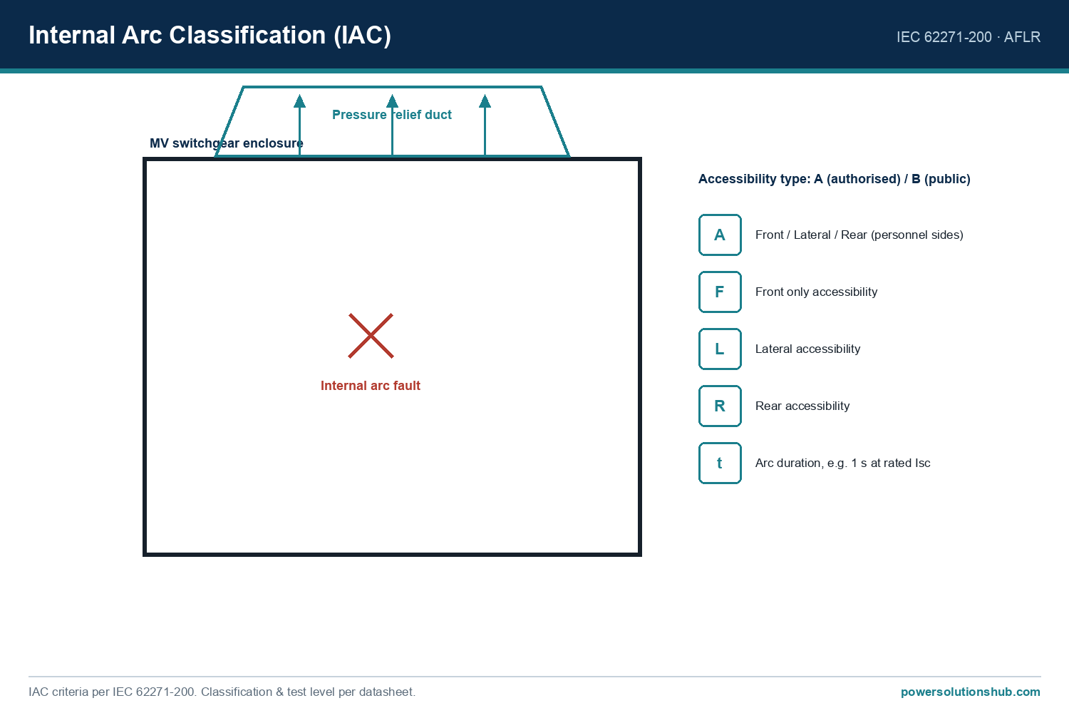
MV switchgear single-line diagrams and the equipment they represent are governed primarily by IEC 62271-1 (common specifications for high-voltage switchgear and controlgear) together with IEC 62271-200 for AC metal-enclosed switchgear rated up to 52 kV, which define rated voltage, rated current, and rated short-circuit breaking current terminology used on the diagram labels. Short-circuit current calculation methodology follows IEC 60909, and cable ampacity cross-checks reference IEC 60287. Diagram symbols themselves generally follow IEC 60617 graphical symbol conventions. Where a project specifies IEEE-based documentation, equivalent ANSI/IEEE device-number conventions (e.g., 50/51/87) are used in the protection relay blocks instead of, or alongside, IEC function labels.
Related guides
See also our guides on gas-insulated switchgear, ring main units and metal-clad switchgear.
What is the difference between a single-line diagram and a schematic (wiring) diagram?
A single-line diagram simplifies a three-phase system into one line per circuit to show power flow, ratings, and protection logic at a glance, while a schematic/wiring diagram shows the actual three-phase (or control) wiring, terminal numbers, and physical connections needed for installation.
How do I calculate the rated current for a feeder shown on an MV SLD?
Use I = S / (√3 × V), where S is the apparent power of the connected load or transformer in kVA and V is the system’s line-to-line voltage in kV, then select the next standard switchgear current rating above the calculated value.
Why does the SLD show a short-circuit current value at the busbar instead of at each feeder?
Because the busbar must withstand the combined fault contribution from every source connected to it, while each feeder breaker only needs to be rated for its own rated current in normal service; the fault-current rating is a busbar-level design parameter applied to every breaker on that busbar.
What do the CT and VT symbols on the diagram represent?
Current transformers (CT) and voltage transformers (VT) step down primary current and voltage to safe, standardized levels for protection relays and metering, and their ratio is shown on the SLD so it can be cross-checked against relay settings.
Can one SLD cover both the medium-voltage and low-voltage sides of a substation?
Yes; it is common to show the MV switchgear, the transformer, and the LV switchboard on one combined diagram, with the transformer symbol marking the voltage transition and its own worked-current calculation on each side.
What is the role of the bus-coupler breaker in a double-busbar SLD?
It allows two busbar sections to be operated independently or joined together, supporting maintenance switching or bus-transfer schemes without interrupting supply to all feeders simultaneously.
Which IEC standard governs the terminology used for ratings shown on an MV switchgear SLD?
IEC 62271-1 and IEC 62271-200 define the rated voltage, rated current, and rated short-circuit breaking current terms used to label MV switchgear panels on the diagram, while IEC 60909 governs the short-circuit calculation method behind those labels.
Looking for medium voltage switchgear?
Looking for high-quality medium voltage switchgear? We provide expert engineering support and reliable products for all your medium voltage needs.
For quotations and requests: info@electricistanbul.com
WhatsApp: +90 501 076 69 91