
An MV switchgear cubicle type is a functional classification — incomer, feeder, bus-coupler, or metering — that defines the role a switchgear panel plays within a medium-voltage distribution board, based on its position in the single-line diagram, the direction of power flow it handles, and the protection/control scheme it hosts. Engineers select and arrange these cubicle types to build a complete switchboard that receives power from a source, distributes it to loads, allows bus sectioning, and provides revenue-grade or check metering. This guide walks through the underlying rated-current and short-circuit logic used to size each cubicle type, with a fully worked numerical example, a comparison table, and practical selection criteria for projects across the Middle East and Gulf (including Egypt and Saudi Arabia), North Africa, the CIS region, and Sub-Saharan Africa.
Why cubicle classification matters
A medium-voltage switchboard is never built from identical panels. Each cubicle in the lineup is optimized for a specific function:
- Incomer (incoming feeder) — connects the switchboard to its upstream source (utility transformer, generator, or another switchboard). It typically carries the full busbar design current and must be rated for the maximum prospective fault level at that point.
- Feeder (outgoing feeder) — distributes power downstream to a transformer, motor, or sub-distribution board. Its rated current is sized to the connected load, not the full bus current.
- Bus-coupler (bus-tie) — links two bus sections so the board can operate as one system or be split for maintenance/fault isolation; it must be capable of carrying current from either section and interrupting fault current from both directions.
- Metering cubicle — houses voltage/current transformers (VTs/CTs) for revenue metering or protection, often with no interrupting device of its own, or with only a disconnector/fuse combination.
Getting the classification wrong — for example, undersizing a bus-coupler because it “just links two buses” — is a common design pitfall, because the bus-coupler must be rated for the same short-circuit duty as the busbar itself, not for a reduced load current. Understanding the current and fault-level logic behind each cubicle type is therefore essential before consulting a hub page such as our MV switchgear overview or a [protection relay](/what-is-a-medium-voltage-protection-relay-mv-protection-relay/) guide for the associated control scheme.
The method: how rated current and fault duty are derived per cubicle
The starting point for sizing any MV cubicle is the three-phase rated current formula:
I (A) = S / (√3 × V)
where S is the apparent power in kVA (or kW/PF for motor loads) and V is the rated line-to-line voltage in kV.
For each cubicle type, this formula is applied differently:
- Incomer — I is calculated from the total transformer/generator rating feeding the board, because the incomer must carry the entire incoming power before it splits to the feeders.
- Feeder — I is calculated from the individual downstream load (a single transformer, motor, or cable route), so multiple feeders on the same bus will each have a smaller, load-specific rated current than the incomer.
- Bus-coupler — I is calculated using the largest expected transfer current between bus sections, which in many designs is taken equal to the full busbar rated current, since the coupler may need to carry the entire load of one section if the other source is lost.
- Metering cubicle — sized by CT/VT ratio selection rather than a breaker current rating; the CT primary current should be chosen close to (but not less than) the expected maximum load current, so the meter operates within its accurate measurement range (commonly 20–120% of CT rated primary current, per typical accuracy-class practice).
Short-circuit withstand duty is a separate, independent calculation from load current. Every cubicle connected to a common busbar — incomer, feeder, bus-coupler alike — must be rated for the same prospective short-circuit current at that busbar, derived from source impedance and system fault-level studies, because a fault anywhere on the bus exposes every connected cubicle to the same fault current magnitude during the fault duration, even though their continuous load currents differ substantially.
Worked example: sizing an incomer, two feeders and a bus-coupler
Consider a simplified single-bus MV switchboard fed by one 11 kV incoming source, supplying two outgoing transformer feeders and split by a bus-coupler into two sections for future expansion.
Step 1 — Incomer rated current
Assume the incoming transformer capacity feeding the board is 5,000 kVA at 11 kV.
I(incomer) = S / (√3 × V) = 5,000 / (1.732 × 11) ≈ 5,000 / 19.05 ≈ 262 A
The incomer cubicle circuit-breaker must therefore be selected with a rated current equal to or above 262 A — commercial breaker frames are chosen at the next standard rating above the calculated value.
Step 2 — Feeder rated currents
Say Feeder 1 supplies a 2,000 kVA distribution transformer and Feeder 2 supplies a 1,500 kVA transformer, both at 11 kV.
I(feeder 1) = 2,000 / (1.732 × 11) ≈ 2,000 / 19.05 ≈ 105 A
I(feeder 2) = 1,500 / (1.732 × 11) ≈ 1,500 / 19.05 ≈ 79 A
Note that the sum of the two feeder currents (105 + 79 ≈ 184 A) is less than the incomer current (262 A), reflecting spare capacity for a third feeder or future load growth — a normal and recommended design margin.
Step 3 — Bus-coupler rated current
Because the bus-coupler must be able to carry the full load of either bus section if the other incomer trips, it is typically sized equal to the incomer rating rather than to the sum of feeder currents. In this example, the bus-coupler would also be selected for at least 262 A, matching the incomer.
Step 4 — Short-circuit duty check
If a fault-level study shows a prospective three-phase short-circuit current of, for example, 20 kA at the 11 kV busbar, then the incomer, both feeders, and the bus-coupler must all be rated to withstand and interrupt that same 20 kA level, even though their continuous currents range from 79 A to 262 A. This illustrates why short-circuit rating and continuous current rating are selected through two separate, independent calculations.
Step 5 — Metering cubicle CT selection
For a metering cubicle monitoring the incomer, if the maximum expected load current is 262 A, a CT with a primary rating such as 300/5 A or 300/1 A would typically be chosen so that normal load operation (roughly 87–95% of CT primary rating) stays within the CT’s accurate measurement range, avoiding both saturation at fault current and poor accuracy at light load.
Comparison table: functional role of each cubicle type
| Cubicle type | Power-flow direction | Rated current basis | Typical short-circuit duty | Main device inside |
|---|---|---|---|---|
| Incomer | Source → busbar | Full source/transformer capacity | Full busbar fault level | Circuit-breaker + protection relay |
| Feeder | Busbar → single load | Individual load (transformer/motor/cable) | Full busbar fault level | Circuit-breaker or contactor-fuse |
| Bus-coupler | Bus section ↔ bus section | Equal to (or near) full busbar current | Full busbar fault level | Circuit-breaker |
| Metering | Measurement only (no load switching) | Sized by CT/VT ratio, not breaker rating | N/A or via associated disconnector | VT + CT, optional disconnector/fuse |
Selection criteria and common pitfalls
- Never size the bus-coupler by “average” feeder current. It must match the busbar’s continuous and short-circuit rating, since it may have to carry the full load of a healthy section during a source outage on the other section.
- Check diversity, not just arithmetic sum. Feeder currents rarely sum to the incomer rating one-for-one; realistic load diversity and future expansion margin should guide incomer sizing, not a bare addition of nameplate feeder currents.
- Match CT accuracy class to purpose. Metering CTs (for billing) need tight accuracy classes at normal load current, while protection CTs (feeding a protection relay) need to remain unsaturated at fault current — the two duties often require separate CT cores even within the same metering cubicle.
- Confirm withdrawable vs. fixed construction per cubicle role. Feeders and incomers are frequently specified as withdrawable for maintenance isolation, while metering cubicles may use fixed-mounted VTs with fused isolation instead of a full breaker.
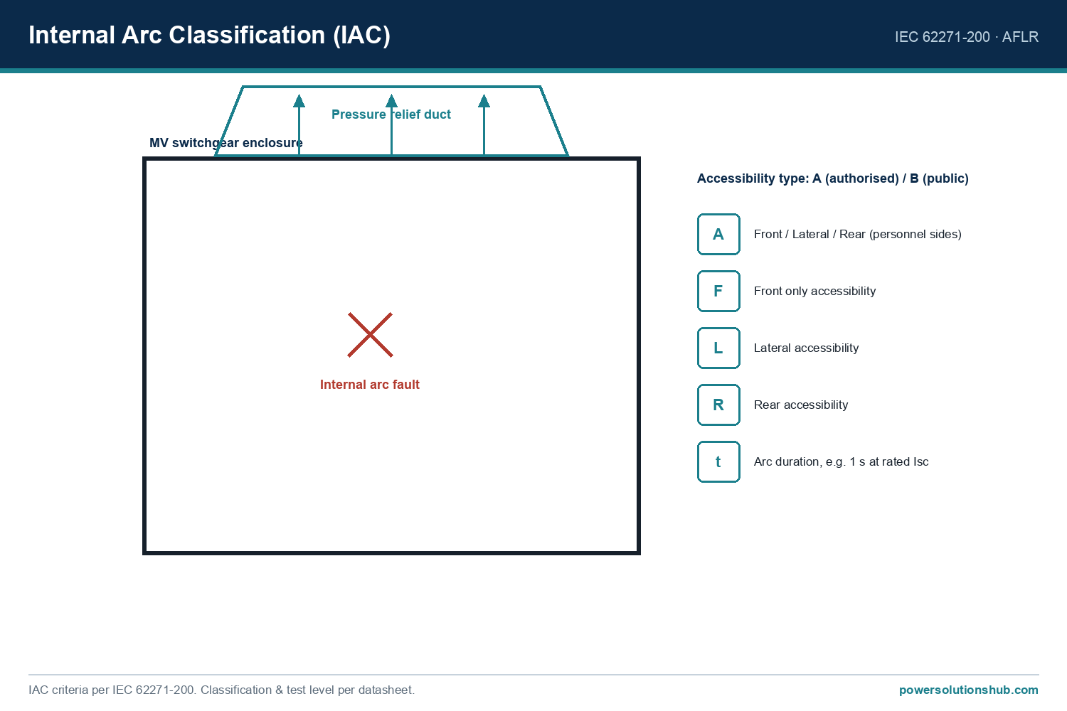
- Validate arc-fault internal classification (IAC) at board level, not per cubicle in isolation — the enclosure design must contain an internal arc regardless of which cubicle type experiences the fault.
- Re-check rated current after transformer upgrades. A common field pitfall is upgrading a downstream transformer’s kVA rating without re-running the feeder’s rated-current calculation, leaving the breaker undersized relative to the new load.
Governing standards
Medium-voltage switchgear cubicle design, type-testing, and internal arc classification are governed by the IEC 62271 series, notably IEC 62271-200 for AC metal-enclosed switchgear rated up to 52 kV, which defines the type tests, temperature-rise limits, and internal arc classification (IAC) methodology applicable to incomer, feeder, bus-coupler, and metering cubicle enclosures alike. Instrument transformers used in metering cubicles are covered separately under IEC 61869 (current and voltage transformers), while protection and control wiring practices reference IEC 60255 for relays. Reviewing these standards alongside our MV switchgear and transformer technical pages helps ensure a cubicle lineup is specified consistently from source to load.
Related guides
See also our guides on gas-insulated switchgear, ring main units and metal-clad switchgear.
What is the difference between an incomer and a feeder cubicle in MV switchgear?
An incomer cubicle receives power from an upstream source and typically carries the full busbar design current, while a feeder cubicle distributes power to a single downstream load and is sized only for that load’s current — resulting in a lower rated current than the incomer in most switchboard designs.
Why is a bus-coupler cubicle rated the same as the incomer?
Because the bus-coupler must be able to carry the entire load of one bus section if the parallel incomer or source becomes unavailable, it is generally sized to the full busbar rated current and fault level, not to a fraction of the total load.
Does a metering cubicle need a circuit-breaker?
Not necessarily. Many metering cubicles use only a disconnector or fuse-switch combination alongside voltage and current transformers, since their function is measurement rather than load switching or fault interruption.
How do you calculate the rated current for an MV feeder cubicle?
Use I = S / (√3 × V), where S is the connected transformer or load rating in kVA and V is the rated line-to-line voltage in kV; the result gives the minimum breaker current rating for that specific feeder.
Do all cubicles in a switchboard need the same short-circuit rating?
Yes — every cubicle connected to a common busbar, regardless of its load current, must be rated for the same prospective short-circuit current at that bus, since a fault exposes the entire section to the same fault magnitude.
What CT ratio should be used in a metering cubicle?
The CT primary rating should be chosen close to, but not below, the expected maximum load current of the circuit being metered, so that normal operating current falls within the CT’s accurate measurement range without risking saturation during fault conditions.
Which IEC standard governs MV switchgear cubicle design?
IEC 62271-200 governs AC metal-enclosed switchgear up to 52 kV, covering type testing and internal arc classification that applies across incomer, feeder, bus-coupler, and metering cubicle types, while IEC 61869 governs the instrument transformers used inside metering cubicles.
Looking for medium voltage switchgear?
Looking for high-quality medium voltage switchgear? We provide expert engineering support and reliable products for all your medium voltage needs.
For quotations and requests: info@electricistanbul.com
WhatsApp: +90 501 076 69 91