
A plug-in cable termination — more precisely a separable connector — is a screened, touch-proof MV cable accessory that pushes onto the bushing of gas-insulated switchgear, so a cable can be connected or disconnected without cutting into the insulation.
This guide explains how a plug-in cable termination works on gas-insulated MV switchgear, the interface types you will meet, the four assembly steps, and how to select the right connector — with common mistakes to avoid.
Why use a plug-in cable termination on gas-insulated switchgear?
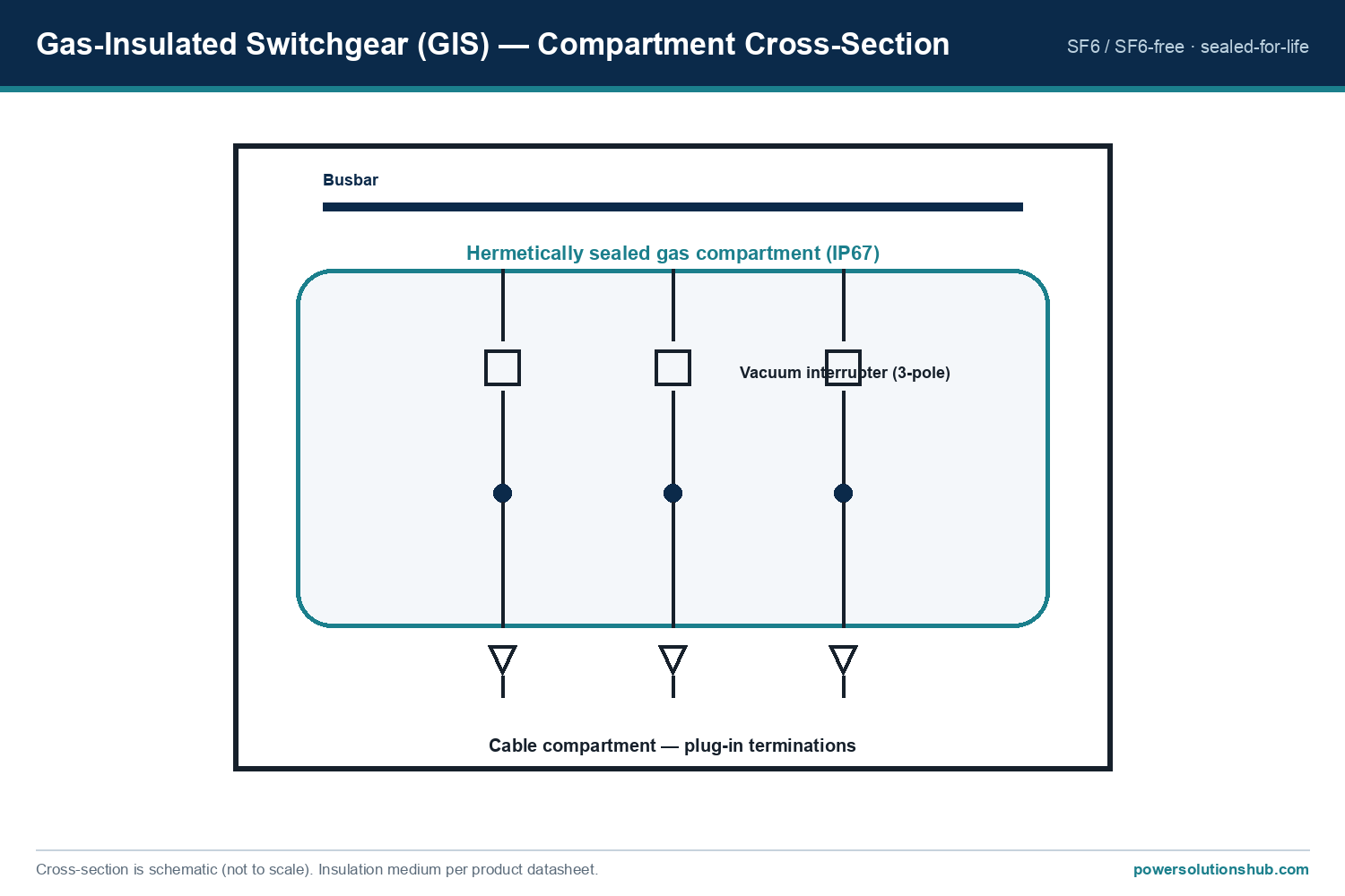
Gas-insulated switchgear (GIS) and ring main units are sealed for life, so their cable connection has to be made from outside the tank, onto standardised bushings. A plug-in cable termination provides exactly that: a screened (fully insulated, earthed outer layer) plug that mates with the bushing, is touch-proof, and can be removed for testing without disturbing the cable. This is what makes the compact, maintenance-free gas-insulated switchgear design practical in the field.
Interface types and current ratings
Separable connectors are standardised by a bushing interface defined in CENELEC EN 50180 / EN 50181, and each interface has a current class. The Nexans Euromold range covers cables from 12 up to 42 kV. The common interfaces are:
| Interface | Rated current | Voltage | Typical Euromold products | Type |
|---|---|---|---|---|
| Interface A | 250 A | up to 24 kV | 158LR elbow, 152SR straight, K200T tee | screened, separable |
| Interface C (400-series) | 630 A | up to 24 kV | K400-series elbow / tee connectors | screened, separable |
| Interface C (480-series) | 1250 A | up to 24 kV | tee / cross connectors | screened, separable |
Interface A (250 A) is the workhorse for distribution transformers and small feeders; the 630 A and 1250 A interfaces are used where the feeder current or ring-through current is higher.
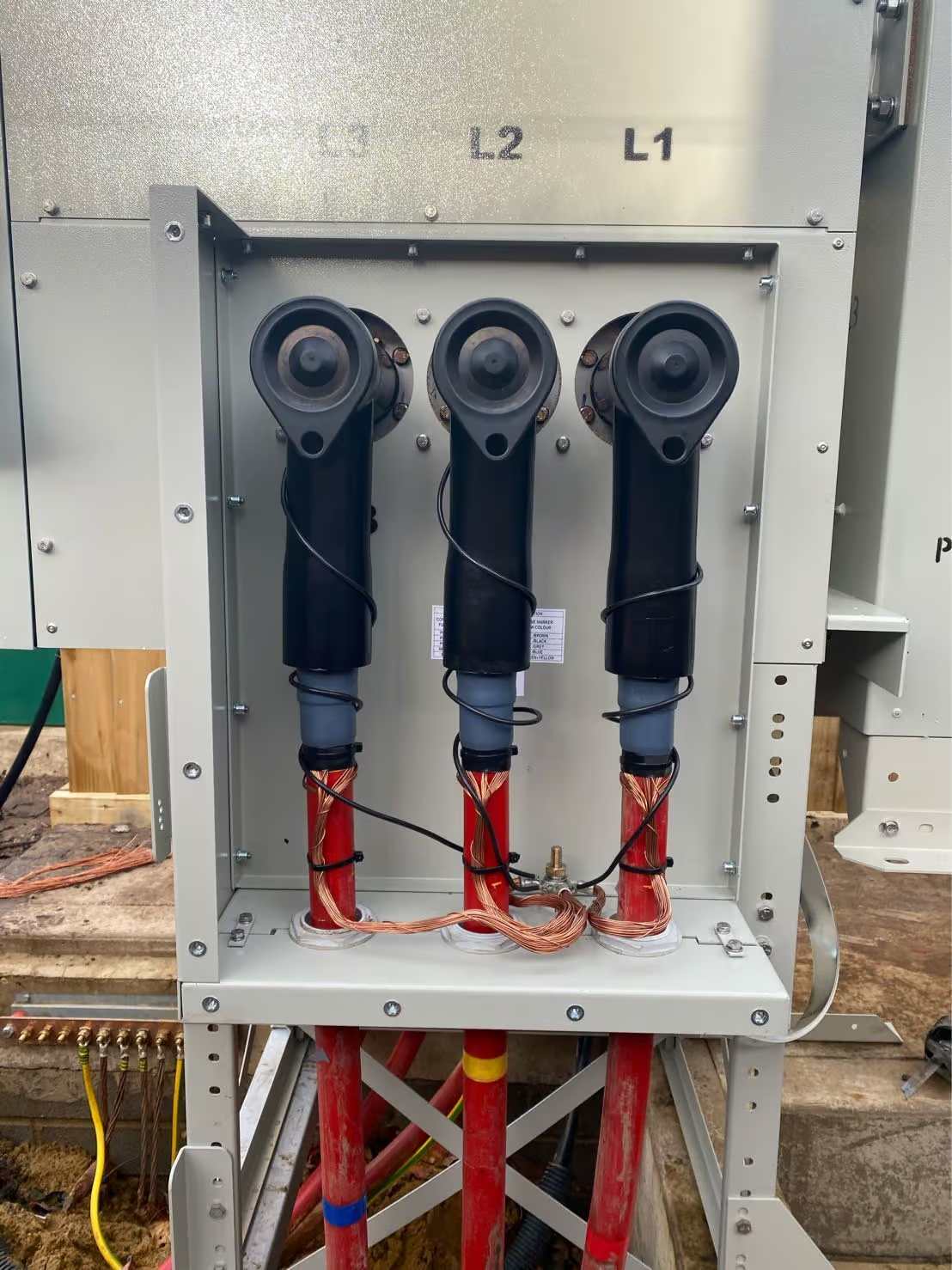
The bushing part accepts interface diameters between 40 and 60 mm, and the system is separable, allowing easy removal for testing. A typical screened elbow connector (e.g. 158LR) is built from a conductive EPDM insert and jacket, a conductor connector, a capacitive voltage test point, and — in the earthed (-G) version — an earthing lead.
Screened vs unscreened — why touch-proof matters
The single most important distinction is whether a connector is screened. A screened separable connector carries a semi-conductive outer layer that is bonded to earth, so the exposed surface stays at earth potential even when the cable is live. That makes the assembly touch-proof and lets it be operated safely inside a compact, sealed switchgear cabinet where clearances are small. Unscreened accessories have no earthed outer layer and are restricted to applications where touch-proofing is not required. On gas-insulated switchgear — where the whole point is a sealed, space-saving enclosure — screened, touch-proof connectors are effectively mandatory. The screened design is also what allows tee and cross connectors to be stacked on a single bushing to build ring and tap-off arrangements.
Function types — elbow, tee and cross
The elbow (angled) connector terminates a single cable onto a bushing; the tee connector provides a through-connection so a bushing can carry the ring plus a tap-off; and the cross connector extends this to multiple tap-offs. Unused positions are closed with dead-end plugs, and surge arresters (e.g. the 156SA) or stand-off / earthing plugs can be added onto the same interface. This building-block approach mirrors the switchgear itself and is why the accessory interface is standardised so strictly.
Fitting a plug-in cable termination: the four steps
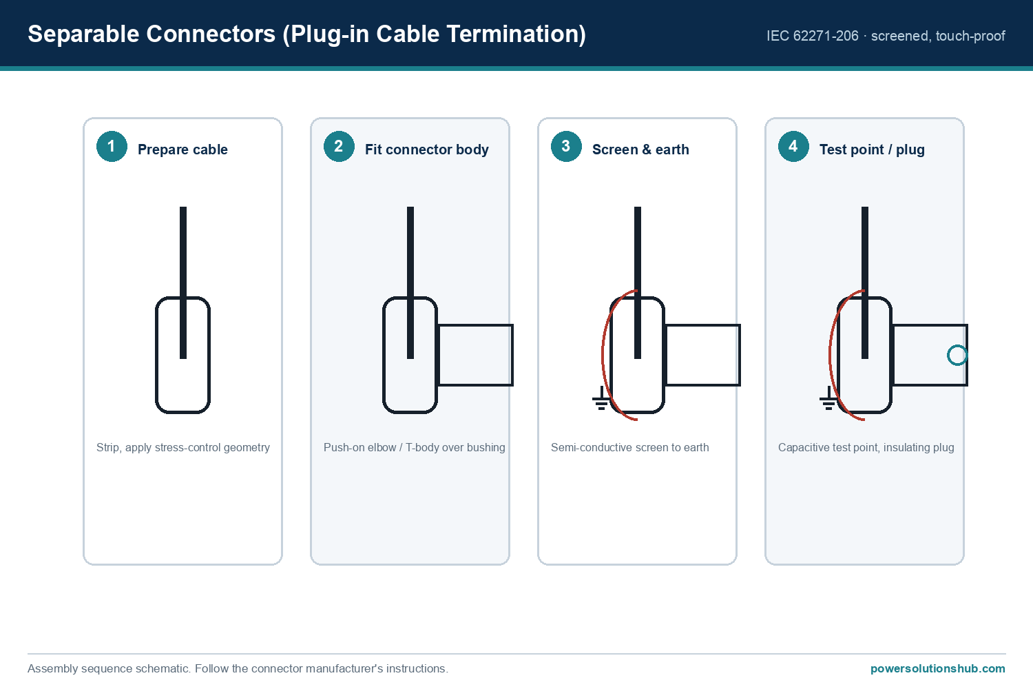
- Prepare the cable. Strip the cable to the connector’s dimensions and apply the stress-control geometry that controls the electric field at the screen cut-back.
- Fit the connector body. Push the elbow or T-body over the equipment bushing until seated.
- Screen and earth. Connect the semi-conductive outer screen to earth, making the assembly touch-proof.
- Test point / plug. Fit the capacitive voltage test point and any insulating plug; unused positions of a tee are closed with a dead-end plug.
Selecting a plug-in cable termination
When you select a plug-in cable termination, five factors decide the right part:
- Interface & current: match Interface A (250 A), 630 A or 1250 A to the feeder current.
- Voltage class: e.g. 12/20 (24) kV — select the connector’s rated voltage above the network’s Ur.
- Cable type: confirm the connector suits the cable’s conductor size and screen type (e.g. copper-tape or wire screen).
- Function: elbow (single cable), tee (through-connection / ring), or cross (multiple tap-offs).
- Standards: the products meet CENELEC HD 629.1, EN 50180/50181, IEC 60502-4 and IEC 60137.
Common mistakes
- Wrong interface pairing — the connector interface must match the switchgear bushing interface (A/C); they are not interchangeable.
- Ignoring stress control — an incorrectly applied stress-control cone leads to partial discharge and early failure.
- Screen not earthed — leaves the assembly no longer touch-proof.
- Skipping the test point — the capacitive test point is needed to verify dead/live status safely before work.
Testing and commissioning
Before energising, the capacitive voltage test point on each connector is used to confirm the circuit is dead, and, after energising, to verify phase presence — without exposing any live metal. On commissioning, cable systems are typically subjected to an insulation and partial-discharge check; because the connector is separable, it can be taken off the bushing for these tests and refitted, which is a practical advantage over fixed heat-shrink terminations. Keeping the interface clean and correctly lubricated at assembly is what ensures a reliable, partial-discharge-free joint over the cable’s life.
A correctly specified plug-in termination is part of a coordinated MV system — the same fault levels that size the short-circuit rating also apply to the connector’s short-circuit withstand.
What is a plug-in cable termination?
A plug-in cable termination is a separable connector: a screened, touch-proof MV cable accessory that pushes onto a switchgear bushing so the cable can be connected or removed without cutting the insulation.
What is the difference between a screened and unscreened separable connector?
A screened connector has an earthed semi-conductive outer layer, making it touch-proof; unscreened types do not and are used only where touch-proofing is not required.
Which interface should I choose?
Match the switchgear bushing: Interface A (250 A) for most distribution feeders, or 630 A / 1250 A interfaces for higher currents.
Can separable connectors be disconnected for testing?
Yes — that is their main advantage. They are separable and include a capacitive voltage test point for safe verification.
What voltage levels do they cover?
The Euromold range covers cables from 12 up to 42 kV.
Looking for Plug-in Cable Terminations (Separable Connectors)?
Looking for high-quality separable connectors and MV cable terminations? We provide expert engineering support and reliable products for all your medium voltage needs.
For quotations and requests: info@electricistanbul.com
WhatsApp: +90 501 076 69 91